Ride On! - CruiserCustomizing
Ride On! - CruiserCustomizing
Ride On! - CruiserCustomizing

You also want an ePaper? Increase the reach of your titles
YUMPU automatically turns print PDFs into web optimized ePapers that Google loves.
ATTENTION! This indication alerts you to the fact that ignoring the contents described herein may<br />
negatively affect product performance and functionality.<br />
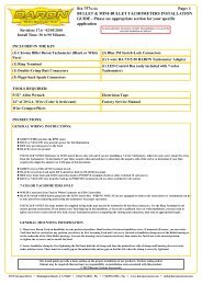
DISCLAIMER – PLEASE READ BEFORE PROCEEDING:<br />
Any modifications to a motorcycle’s exhaust or intake tract require carburetor re-jetting to<br />
achieve maximum performance and maintain drivability. If you are uncomfortable with<br />
the process of tuning your carburetor, we recommend that you bring your motorcycle to a<br />
qualified motorcycle mechanic to have this kit installed. The jets included in this kit were<br />
selected based on test results with various combinations of components that we felt would<br />
represent the majority of the customers purchasing this kit (see Addendum I).<br />
However, no two motorcycles are exactly alike. Depending on the individual case, additional<br />
jets may need to be purchased from an outside source. Kuryakyn warrants the parts included<br />
in this kit to be free of defects in materials and workmanship, but makes no claim whatsoever<br />
in regard to costs associated with installation or tuning.<br />
strIctly Observe the fOllOwIng guIdelInes In Order tO use the<br />
PrOduct PrOPerly and avOId POtentIally dangerOus accIdents.<br />
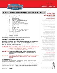
PrOcedure<br />
steP 1 Remove the driver and passenger seats from the bike. Remove the negative battery cable<br />
from the battery.<br />
steP 2 Remove the two rear tank mounting bolts. Remove the plastic tank mounting snap stud.<br />
(Push in on its center to release). Slide the tank back to expose the top of the engine. Make sure the<br />
tank is solidly in place so it does not fall! You may remove the tank completely from the bike if<br />
you’re not certain the tank will stay in place while you are performing this installation.<br />
steP 3 Remove the stock air cleaner cover, element, and backing plate. The top and rear<br />
mounts are secured with screws, the front mount “snaps” into a grommet.<br />
steP 4 See PIC.1 and PIC.2. Remove the grommet from the bracket.<br />
steP 5 With a long shaft Phillips screwdriver as shown in PIC.3, loosen the clamp on the<br />
air duct and remove the duct. Remove and set aside the clamp from the duct, it will be reused.<br />
steP 6 Re-jet carburetor. Refer to factory service manual for disassembly procedure and<br />
to Addendum I for baseline jetting recommendations.<br />
steP 7 Install a Line Fitting Plug into the threaded hole in the Skull Air Cleaner back<br />
plate labeled as “A” in PIC.4 and tighten snugly.<br />
steP 8 Install a 90 Degree Elbow into the threaded hole on the Skull Air Cleaner back<br />
plate labeled as “B” in PIC.4. Tighten snugly.<br />
steP 9 Insert both flanges of the rubber air duct through the opening in the mounting<br />
bracket. See PIC.5.<br />
PIc.5<br />
steP 10 Wet the radius portion of the intake duct<br />
with soapy water solution and slide the Skull Air Cleaner<br />
back plate into place on the intake assembly. See PIC.6.<br />
When positioned correctly, the Skull Air Cleaner back<br />
plate should be between the two rubber flanges on the<br />
intake duct and the 90 Degree Elbow and Line Fitting<br />
Plug will be below the rubber intake duct.<br />
-cont.-<br />
Page<br />
2<br />
s k u l l a I r c l e a n e r<br />
PIc.1<br />
PIc.3<br />
PIc.4<br />
PIc.2<br />
A B<br />
InstallatI<strong>On</strong><br />
®