Ride On! - CruiserCustomizing
Ride On! - CruiserCustomizing
Ride On! - CruiserCustomizing

Create successful ePaper yourself
Turn your PDF publications into a flip-book with our unique Google optimized e-Paper software.
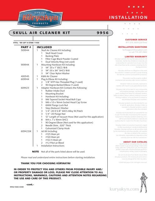
s k u l l a I r c l e a n e r k I t 9 9 5 6<br />
fIts: ‘99-uP v-star 1100<br />
Part # Included<br />
509944 1 Skull Air Cleaner Kit Including:<br />
1 Skull Head Cover<br />
1 Backing Plate<br />
1 Filter Cage Black Powder Coated<br />
1 Dual Velocity Ring (not used)<br />
909944 1 Mounting Hardware Kit Including:<br />
3 1⁄4” 20 x 1” BSCS 18-8<br />
3 1⁄4”-20 x 3⁄4” SHCS 18-8<br />
3 1⁄4” Clear Nylon Washer<br />
400545 1 K&N Air Cleaner<br />
609944 1 Plug & Elbow Kit Including:<br />
2 1/8” NTP Hex Threaded Plug (1 used)<br />
2 90 Degree Barbed Elbow (1 used)<br />
609423 1 Adapter Hardware Kit Contains the Following:<br />
1 Rubber Intake Duct<br />
1 Mounting Bracket<br />
1 Hardware Kit Including:<br />
3 M6 Tapered Socket Head Bolt Caps<br />
3 M6 x 1.0 x 16mm Socket Head Cap Screw<br />
1 6MM Flange Lock Nut<br />
1 Step (Reducer) Washer<br />
3 1/4”–20 X 5/8” SHCS Alloy W/Patch<br />
3 1/4”–20 Flange Nut<br />
1 12” Length of Vacuum Hose (Not used for this application)<br />
8 M4 x .7 x 10mm SHCS<br />
1 90 Degree Elbow (Not used for this application)<br />
2 Needle Shim, .020” Thick<br />
1 Galvanized Clamp Hook<br />
609423JK 1 Jet Kit Including:<br />
1 #125 Main jet<br />
1 #120 Main jet<br />
1 #122.5 Main jet<br />
2 #1.2 Pilot air Bleed<br />
1 Installation Instructions<br />
nOte Not all of the parts listed above will be used.<br />
Please read and understand entire instructions before starting installation.<br />
thank yOu fOr chOOsIng küryakyn!<br />
In Order tO PrOtect yOu and Others frOm POssIble Injury and/<br />
Or PrOPerty damage Or lOss, Please Pay clOse attentI<strong>On</strong> tO all<br />
InstructI<strong>On</strong>s, warnIngs, cautI<strong>On</strong>s and attentI<strong>On</strong> nOtes regardIng<br />
the use and care Of thIs PrOduct.<br />
9956-13MC-0308<br />
-cont.-<br />
I N S TA L L AT I O N<br />
CUSTOMER SERVICE<br />
877.370.3604 (toll free)<br />
INSTALLATION QUESTIONS<br />
techsupport@kuryakyn.com<br />
or call 715.247.2983<br />
LIMITED WARRANTY<br />
Küryakyn warrants that any Küryakyn products sold<br />
hereunder, shall be free of defects in materials and<br />
workmanship for a period of one (1) year from the<br />
date of purchase by the consumer excepting the following<br />
provisions:<br />
• Küryakyn shall have no obligation in the event<br />
the customer is unable to provide a receipt showing<br />
the date the customer purchased the product(s).<br />
• The product must be properly installed,<br />
maintained and operated under normal conditions.<br />
• Küryakyn makes no warranty, expressed or<br />
implied, with respect to any gold plated products.<br />
• Küryakyn shall not be liable for any consequential<br />
and incidental damages, including labor and<br />
paint, resulting from failure of a Küryakyn product,<br />
failure to deliver, delay in delivery, delivery in nonconforming<br />
condition, or for any breech of contract or<br />
duty between Küryakyn and a customer.<br />
• Küryakyn products are often intended for use<br />
in specific applications. Küryakyn makes no<br />
warranty if a Küryakyn product is used in<br />
applications other than intended.<br />
• Küryakyn electrical products are warranted for one<br />
(1) year from the date of purchase by the consumer.<br />
Components of Küryakyn products containing L.E.D.s<br />
will be warranted for defects in materials and<br />
workmanship for 3 years from the date of purchase.<br />
• Küryakyn makes no warranty of any kind in regard<br />
to other manufacturer’s products distributed by<br />
Küryakyn. Küryakyn will pass on all warranties made<br />
by the manufacturer and where possible, will expedite<br />
the claim on behalf of the customer,<br />
but ultimately, responsibility for disposition of the<br />
warranty claim lies with the manufacturer.<br />
ABOUT OUR CATALOG<br />
You’ll find all our innovations for H-D, GL and<br />
Metric Cruisers in our annual catalogs. Order online<br />
today–select the ”CATALOGS” icon. Each Küryakyn<br />
product comes with a Proof-of-Purchase good for a<br />
complimentary catalog. Details in packaging.<br />
Be sure to ask your local dealer about other<br />
Küryakyn products, the motorcycle parts and accessories<br />
designed for riders by riders.<br />
©2005 Küryakyn USA All Rights reserved.
ATTENTION! This indication alerts you to the fact that ignoring the contents described herein may<br />
negatively affect product performance and functionality.<br />
DISCLAIMER – PLEASE READ BEFORE PROCEEDING:<br />
Any modifications to a motorcycle’s exhaust or intake tract require carburetor re-jetting to<br />
achieve maximum performance and maintain drivability. If you are uncomfortable with<br />
the process of tuning your carburetor, we recommend that you bring your motorcycle to a<br />
qualified motorcycle mechanic to have this kit installed. The jets included in this kit were<br />
selected based on test results with various combinations of components that we felt would<br />
represent the majority of the customers purchasing this kit (see Addendum I).<br />
However, no two motorcycles are exactly alike. Depending on the individual case, additional<br />
jets may need to be purchased from an outside source. Kuryakyn warrants the parts included<br />
in this kit to be free of defects in materials and workmanship, but makes no claim whatsoever<br />
in regard to costs associated with installation or tuning.<br />
strIctly Observe the fOllOwIng guIdelInes In Order tO use the<br />
PrOduct PrOPerly and avOId POtentIally dangerOus accIdents.<br />
PrOcedure<br />
steP 1 Remove the driver and passenger seats from the bike. Remove the negative battery cable<br />
from the battery.<br />
steP 2 Remove the two rear tank mounting bolts. Remove the plastic tank mounting snap stud.<br />
(Push in on its center to release). Slide the tank back to expose the top of the engine. Make sure the<br />
tank is solidly in place so it does not fall! You may remove the tank completely from the bike if<br />
you’re not certain the tank will stay in place while you are performing this installation.<br />
steP 3 Remove the stock air cleaner cover, element, and backing plate. The top and rear<br />
mounts are secured with screws, the front mount “snaps” into a grommet.<br />
steP 4 See PIC.1 and PIC.2. Remove the grommet from the bracket.<br />
steP 5 With a long shaft Phillips screwdriver as shown in PIC.3, loosen the clamp on the<br />
air duct and remove the duct. Remove and set aside the clamp from the duct, it will be reused.<br />
steP 6 Re-jet carburetor. Refer to factory service manual for disassembly procedure and<br />
to Addendum I for baseline jetting recommendations.<br />
steP 7 Install a Line Fitting Plug into the threaded hole in the Skull Air Cleaner back<br />
plate labeled as “A” in PIC.4 and tighten snugly.<br />
steP 8 Install a 90 Degree Elbow into the threaded hole on the Skull Air Cleaner back<br />
plate labeled as “B” in PIC.4. Tighten snugly.<br />
steP 9 Insert both flanges of the rubber air duct through the opening in the mounting<br />
bracket. See PIC.5.<br />
PIc.5<br />
steP 10 Wet the radius portion of the intake duct<br />
with soapy water solution and slide the Skull Air Cleaner<br />
back plate into place on the intake assembly. See PIC.6.<br />
When positioned correctly, the Skull Air Cleaner back<br />
plate should be between the two rubber flanges on the<br />
intake duct and the 90 Degree Elbow and Line Fitting<br />
Plug will be below the rubber intake duct.<br />
-cont.-<br />
Page<br />
2<br />
s k u l l a I r c l e a n e r<br />
PIc.1<br />
PIc.3<br />
PIc.4<br />
PIc.2<br />
A B<br />
InstallatI<strong>On</strong><br />
®
steP 11 Line up the three holes in the back plate and the three holes in the flange of the rubber<br />
intake duct with the three holes in the support bracket. Insert the three supplied 1/4”-20 x 5/8”<br />
socket head cap screws through the face of the Skull Air Cleaner back plate and secure on the back<br />
side of the main support bracket with the 1/4”-20 thin Nylock nuts. You will need to pull back the<br />
inner flange of the rubber intake duct to access the holes. Hold the Nylock nuts with a<br />
1/2” wrench as you tighten the socket head cap screws with a 3/16” hex key. See PIC.6.<br />
steP 12 Place the galvanized clamp hook on the duct clamp as shown in PIC.6A.<br />
You will need to flatten this hook on the clamp. Place the Stock duct clamp on the new<br />
intake duct. The clamp screw should face forward. See PIC.6B.<br />
steP 13 See PIC.7. Loosely install the mounting bracket and duct using the included<br />
M6 x 1.25 x 15mm socket heads and tapered socket head bolt caps, the front location<br />
will also require the step (reducer) washer and the M6 flanged nut. Slide the intake<br />
duct onto the air box but do not tighten the clamp at this time. Loosen the clamps<br />
securing the stock rubber elbows to the carburetors and air box. Gently wiggle the air<br />
box to ensure that the rubber intake duct is fully seated on the air box inlet<br />
(removing the air box lid makes it much easier to see if it is on completely).<br />
<strong>On</strong>ce everything is situated and comfortably in place, tighten the clamp on<br />
the rubber intake duct first and then tighten the clamps on the stock rubber<br />
elbows. Replace the air box lid. Tighten the mounting bracket fasteners<br />
completely at this time. (PIC.7 shows the assembly thus far with out the back<br />
plate installed).<br />
steP 14 Set the air filters into position on the back plate. Place the filter<br />
cage over the filter and secure be threading in and tightening the three 1⁄4”-20<br />
x 1” BSCS fasteners from the back side of the back plate into the filter cage.<br />
steP 15 Set the Skull Cover in place, lining up the 3 mounting holes. Insert and tighten<br />
the three 1⁄4”-20 x 3⁄4” SHCS fasteners and clear nylon washers through the skull cover<br />
securing it to the air cleaner assembly. It would be a good idea to use blue lock tight (not<br />
supplied) on these 3 fasteners. Do not over tighten.<br />
steP 16 See PIC.8.This is the float bowl vent hose. Connect this hose to the 90 Degree<br />
fitting on the back plate.<br />
steP 17 Replace the fuel tank and re-connect the negative battery cable, re-install<br />
seats.<br />
steP 18 Recheck to make sure all fasteners are secure, no hoses are kinked, and<br />
throttle operates freely.<br />
ATTENTION! It is the installers’ responsibility to make sure all fasteners (including<br />
pre-assembled) are tightened before operation of motorcycle. Küryakyn<br />
will not warranty components that are lost due to improper installation.<br />
Periodic maintenance may be required.<br />
addendum I.<br />
The following recommendations are to be used as a<br />
starting point only, but should work well in the majority<br />
of cases. Individual bikes may need additional tuning to<br />
achieve maximum performance. These baselines were<br />
established at 700 feet above sea level.<br />
-cont.-<br />
PIc.8<br />
s k u l l a I r c l e a n e r<br />
PIc.6<br />
PIc.6a<br />
PIc.6b<br />
PIc.7<br />
Page<br />
3<br />
InstallatI<strong>On</strong><br />
®
fIg.1<br />
Page<br />
4<br />
s k u l l a I r c l e a n e r<br />
InstallatI<strong>On</strong><br />
®
v-star wIth stOck PIPes<br />
• 1.2 Pilot Air Bleeds in both carburetors<br />
• <strong>On</strong>e .020 shim added to raise each needle<br />
• 122.5 Main Jet in the front cylinder’s carb<br />
• 120 Main Jet in the rear cylinder’s carb<br />
• Pilot Mixture Screw (PMS) 2 turns out from lightly bottomed<br />
v-star wIth vance & hInes, sams<strong>On</strong>, Or OPen “drag” PIPes<br />
• 1.2 Pilot Air Bleeds in both carbs<br />
• <strong>On</strong>e .020 shim added to raise each needle<br />
• 125 Main Jet in the front cylinder’s carb<br />
• 122.5 Main Jet in the rear cylinder’s carb<br />
• Pilot Mixture Screw (PMS) 2 turns out from lightly bottomed<br />
nOtes<br />
1. The factory installed plug covering the PMS will have to be removed in order to access the screw.<br />
2. Because the float bowl screws are easily damage during removal, we have included eight M4 x .7<br />
x 10mm SHCS replacement float bowl screws, just in case they are needed.<br />
<strong>Ride</strong> <strong>On</strong>!<br />
fIg.2<br />
s k u l l a I r c l e a n e r<br />
Page<br />
5<br />
InstallatI<strong>On</strong><br />
®