View installation guide - CruiserCustomizing
View installation guide - CruiserCustomizing
View installation guide - CruiserCustomizing

You also want an ePaper? Increase the reach of your titles
YUMPU automatically turns print PDFs into web optimized ePapers that Google loves.
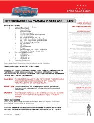
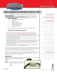
Revision: 17.6 - 02/03/2010<br />
Install Time: 30 to 90 Minutes<br />
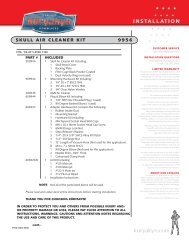
INCLUDED IN THE KIT:<br />
(1) Chrome Billet Baron Tachometer (Black or White<br />
Face)<br />
(1) Ring Terminal<br />
(1) Double-Crimp Butt Connectors<br />
(3) Piggy-back Spade Connectors<br />
TOOLS REQUIRED:<br />
5/32" Allen Wrench<br />
24" of 20 GA. Wire (Color is irrelevant)<br />
Wire Crimper/Pliers<br />
INSTRUCTIONS:<br />
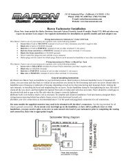
GENERAL WIRING INSTRUCTIONS:<br />
GREEN WIRE provides the RPM count<br />
BLUE or YELLOW wire provides power for the illumination<br />
RED wire provides power to the Tach<br />
BLACK wire is for ground<br />
BA-757x-xx<br />
Page: 1<br />
BULLET & MINI-BULLET TACHOMETERS INSTALLATION<br />
GUIDE - Please see appropriate section for your specific<br />
application<br />
Go slowly and follow instructions carefully. The <strong>installation</strong> is very easy if the<br />
wire color destinations are followed.<br />
(3) Blue 3M Scotch-Lock Connectors<br />
(1) 3-wire BA-7315-50 BARON Tachometer Adapter<br />
(1) LED Control Box (only included with 7-color<br />
Tachometer)<br />
Electrician Tape<br />
Factory Service Manual<br />
INSTALLER NOTES: Reference to LED Control Box is only relevant if you are installing a 7-Color Tachometer, otherwise only worry about the wires<br />
from the Tachometer. To determine if your bikes requires this unit and how to determine the negative side of the coil or to determine if your bike<br />
requires the single fire adapter see FAQ page of this document.<br />
GREEN wire to NEGATIVE terminal of coil.<br />
BLACK wires from Tach and LED Control box both to CHASSIS (Ground)<br />
RED wires from Tach and LED Control box both to POSITIVE terminal of coil (or other switched 12 volt source)<br />
BLUE or YELLOW wire from the Tach go to POSITIVE terminal of coil (or other switched 12 volt source)<br />
7-COLOR TACHOMETERS ONLY<br />
WHITE Connector from Tach to White Connector on LED Control Box<br />
BLACK Switch w/RED button plugs into the LED Control Box WIRING NOTE: If you are equipped to solder your connections we recommend you do<br />
so only after first connecting and testing the tachometer for proper operation.<br />
INSTALLER NOTES: On some models the supplied wiring leads may need to be trimmed to fit the bikes connectors. Use the Ring Terminal for all<br />
chassis ground connections. If you mount your Tach high up on the handlebar, or have tall or pullback risers or wide handlebars, you may need to<br />
splice extra wire to each colored wire lead of your Tachometer prior to completing the routing and connection, then trim to appropriate length.<br />
GENERAL MOUNTING INFORMATION<br />
1. Mount new Baron Tach on handlebar in your preferred position. Ideal location is between handlebar risers. If mounted off-center, you can rotate<br />
Tach face back to vertical (or any position you desire) by first loosening Tach unit's set screw (located in handlebar clamp area of the Bullet housing or<br />
on the underside of the Mini-Bullet housing). Unscrew the housing's bezel (counterclockwise) then rotate the Tach Face to the desired position,<br />
re-tighten the set screw and re-install the bezel.<br />
2. Secure handlebar clamp by first tightening the flat/front dial side of clamp and then the pointed/rear side of clamp until housing does not rotate<br />
under mild pressure. There must be a small gap on the pointed side and no gap on the flat side when the clamp is correctly tightened.<br />
Our install <strong>guide</strong>s provide a basic outline on the proper <strong>installation</strong> of our products. Further tuning and/or<br />
fitment may be required. Barons bears no responsibility on <strong>installation</strong> costs associated with this product.<br />
© 2012 Barons Custom Accessories<br />
5221 Oceanus Drive Huntington Beach, CA 92649 (714)274-4065 - Ph. (714)901-0520 - Fax www.baronscustom.com tech@baronscustom.com
BA-757x-xx<br />
Page: 2<br />
BULLET & MINI-BULLET TACHOMETERS INSTALLATION<br />
GUIDE - Please see appropriate section for your specific<br />
application<br />
CLAMP GAP NOTE: To prevent fogging be sure to not close the pointed end of the clamp together as this is where the hidden breather vents are<br />
located that provide a constant air exchange.<br />
3. Route Tach's wire harness lead under the dash for simplest and cleanest <strong>installation</strong>.<br />
1980 to 2003 HARLEY-DAVIDSONS<br />
NOTE: LED Control Box references are only relevant to 7-Color Tachometers. If you have a single color model you will only be concerned with the<br />
wires exiting the Tachometer.<br />
Making your wire connections as follows will not require the use of the Tach Adapter:<br />
GREEN WIRE: Find the PINK wire from the factory wiring harness located under the speedometer (sometimes they have a plastic bullet<br />
shaped end). Cut the plastic off and splice the PINK wire to the GREEN wire from the Tachometer.<br />
BLUE/YELLOW & RED WIRES: Find the ORANGE wire under the dash and attach the Tach power wires BLUE & RED (incandescent) or<br />
YELLOW & RED (single color LED Tachs) to it. On 7-Color LED Tachometers connect RED from the Tach and RED from the LED controller<br />
box.<br />
BLACK WIRE: Locate a suitable ground (usually a bare frame bolt) and attach the BLACK wires from the Tachometer and the LED<br />
controller box (if equipped) using the ring connector.<br />
7-COLOR TACHOMETERS ONLY<br />
WHITE WIRE: White Connector from 7-Color Tach to WHITE Connector on the 7-Color LED Control Box<br />
BLACK SWITCH: w/Red Button plugs into 7-Color LED Control Box<br />
2004 - 2010 HARLEY-DAVIDSONS<br />
ALL MODELS REQUIRE TACH ADAPTER<br />
TACH ADAPTER: The 2004-2010 Harley Davidson will need to utilize the Baron Tach Adapter (BA-7315-50 which is included with your Tach<br />
Kit).<br />
1. Remove the seat & fuel tank per the factory service manual.<br />
2. Remove the plastic wiring harness cover that runs the length of the backbone under the tank.<br />
3. On the left side is the coil harness. Locate the following wires:<br />
YELLOW w/BLUE Tracer, BLUE w/ORANGE Tracer, YELLOW w/GREEN Tracer. These will be used in later steps. NOTE:There are 2<br />
wires you will be using that look VERY SIMILAR. Please pay attention to the ones you connect to, as the Tach will only work if the instructions<br />
below are followed exactly.<br />
WIRE THE TACHOMETER & ADAPTER AS FOLLOWS:<br />
YELLOW WIRE: Use a Scotch-Loc to connect the YELLOW lead from the Tach Adapter to the YELLOW w/BLUE Tracer coil wire.<br />
BLUE WIRE: Use a Scotch-Loc to connect the BLUE lead from the Tach Adapter to the BLUE w/ORANGE tracer coil wire.<br />
GREEN WIRE: Connect the GREEN wire from the Tach adapter to the GREEN wire from the Tachometer with the included Red butt<br />
connector. The GREEN wires ONLY connect to one another; DO NOT CONNECT them to any positive power source or you will burn the unit<br />
out.<br />
BLUE/YELLOW & RED WIRES: Find switched power from the bike (you can use the ORANGE wire from the bikes harness or the<br />
YELLOW w/GREEN Tracer wire). Use a Scotch-Loc to connect either the BLUE & RED wires (incandescent Tach model), or the YELLOW &<br />
RED wires (single-color LED Tach model) and splice them to the YELLOW w/GREEN Tracer wire on your harness. For 7-color LED Tachs,<br />
use the RED wire from the Tach and the RED wire from the LED controller box and splice them to the YELLOW w/GREEN Tracer wire on<br />
your harness.<br />
BLACK WIRE: Attach BLACK wire from the Tachometer and LED Control Box on 7-Color Tachometers to a suitable ground (usually a bare<br />
frame bolt). Use the Ring terminal (supplied).<br />
7-COLOR TACHOMETERS ONLY<br />
WHITE WIRE: White Connector from 7-Color Tach to WHITE Connector on the 7-Color LED Control Box<br />
BLACK SWITCH: w/Red Button plugs into 7-Color LED Control Box<br />
Our install <strong>guide</strong>s provide a basic outline on the proper <strong>installation</strong> of our products. Further tuning and/or<br />
fitment may be required. Barons bears no responsibility on <strong>installation</strong> costs associated with this product.<br />
© 2012 Barons Custom Accessories<br />
5221 Oceanus Drive Huntington Beach, CA 92649 (714)274-4065 - Ph. (714)901-0520 - Fax www.baronscustom.com tech@baronscustom.com
BA-757x-xx<br />
Page: 3<br />
BULLET & MINI-BULLET TACHOMETERS INSTALLATION<br />
GUIDE - Please see appropriate section for your specific<br />
application<br />
UNIVERSAL TACHOMETER INSTRUCTIONS FOR METRIC & BRANDS OTHER THAN<br />
HARLEY-DAVIDSON<br />
These instructions cover installing this Tach on most Metric and Non Harley motorcycles. Some vehicles may require the included Tach<br />
adapter. Please see FAQ on the final page of the instructions for information on how to determine whether your bike requires the Tach Adapter.<br />
Wiring instructions are included separately for the adapter.<br />
Tools required:<br />
2.5, 4 & 5MM Allen Wrenches<br />
10 & 12 MM Sockets<br />
10MM Open-end wrench<br />
Pliers (Std. & Needle Nose)<br />
Electrical Tape / Shrink Tube<br />
Factory Service Manual<br />
INSTALLER NOTES: Reference to LED Control Box is only relevant if you are installing a 7-Color Tachometer, otherwise only worry<br />
about the wires from the Tachometer. To determine if your bikes requires the BA-7515-50 Tach Adapter and how to locate the negative<br />
side of the coil see FAQ page of this document.<br />
WIRING INSTRUCTIONS:<br />
Wire Baron's Tach to one of your motorcycles ignition coils via the following method:<br />
GREEN WIRE from Tach to NEGATIVE terminal of coil (or direct to Green from the Tach Adapter if your bike requires the single fire<br />
adapter.<br />
BLACK WIRE from Tach and the LED Control box on 7-Color Tachometer both go to CHASSIS (Ground)<br />
RED WIRE from Tach and LED Control box on 7-Color Tachometer both go to POSITIVE terminal of coil (or other switched 12 volt<br />
source)<br />
7-COLOR TACHOMETERS ONLY<br />
WHITE Connector from 7-Color Tach to WHITE Connector on the 7-Color LED Control Box<br />
BLACK SWITCH box w/Red Button plugs into 7-Color LED Control Box<br />
FREQUENTLY ASKED QUESTIONS (FAQ):<br />
We appreciate your business and hope you have had a successful <strong>installation</strong>. Should you be experiencing any oddities, or have questions<br />
we would appreciate you taking a moment to review the information below. You will find answers to the most common questions and<br />
explanations that will in most cases take care of your needs. If after reviewing the information and you are still having issues , please<br />
contact us by email at TECH@Baronscustom.com or on our TECH phone at 714-274-4098.<br />
TACH ADAPTER<br />
Q: How do I know if I need the Tach Adapter (BA-7315-50)<br />
A. In most cases if your bike has a fuel-injected or single-fire ignition you will need the Tach Adapter.<br />
Q. I installed the Tach and it seems to be registering half the RPM's, whats wrong?<br />
A. You most likely need the Adapter.<br />
TACH ADAPTER KNOWN FITMENT<br />
We have tested this adapter and determined:<br />
IT IS REQUIRED ON All HARLEY DAVIDSON Models 2004-2010, YAMAHA V-Star 950 & 1300, 2008-2009 Road Star, Warrior,<br />
Roadliner, Stratoliner, Raider, HONDA VTX1800 , KAWASAKI VN900 & VN2000, SUZUKI C50 & C90<br />
IT IS NOT REQUIRED ON: HARLEY DAVIDSON models using the stock Tach output from the bike (PINK wire), YAMAHA Road<br />
Star, Royal Star, RSTD, Venture or 1998 to 2010 Vstar 650 & 1100, KAWASAKI VN1500/VN1600 Models, HONDA VTX1300<br />
ELECTRONIC FUEL INJECTION (EFI)<br />
This adapter may or may not be required on fuel-injected 2 or 4-cylinder bikes not listed above. If you have installed the Tach and it is<br />
registering half the RPM's needed you would most likely need the Tach Adapter.<br />
BULB REPLACEMENT<br />
Q: How do I replace the light bulb in my Tach?<br />
A: Remove Tach from the handlebars. In the handlebar clamp area of the Tach housing there is a set screw: Loosen it, remove the Tach<br />
housing bezel by unscrewing (counterclockwise) from the housing, slide the Tach instrument out of the housing. On the rear of the<br />
Stainless Steel Tach unit there is a rubber plug: Remove the plug. The bulb is in a bayonet style holder just under the plug. Rotate holder<br />
1/4 turn to remove, and pull the bulb out.<br />
Our install <strong>guide</strong>s provide a basic outline on the proper <strong>installation</strong> of our products. Further tuning and/or<br />
fitment may be required. Barons bears no responsibility on <strong>installation</strong> costs associated with this product.<br />
© 2012 Barons Custom Accessories<br />
5221 Oceanus Drive Huntington Beach, CA 92649 (714)274-4065 - Ph. (714)901-0520 - Fax www.baronscustom.com tech@baronscustom.com
BA-757x-xx<br />
Page: 4<br />
BULLET & MINI-BULLET TACHOMETERS INSTALLATION<br />
GUIDE - Please see appropriate section for your specific<br />
application<br />
REPLACEMENT BULB - .10A 14V T-1 3/4 WEDGE, #18 MINIATURE BULB GLASS WEDGE BASE like a Sylvania 74 or equivalent<br />
GE74.BP221029 style which are available at most auto parts stores or online light bulb suppliers.<br />
LED ILLUMINATION<br />
7-color LED or Single Color LED Tachometers do not have replaceable light sources. However, LEDs typically last a very long time so<br />
it is unlikely you will have an issue.<br />
NEEDLE BOUNCING<br />
Q: My Tach is bouncing at idle, what does this mean?<br />
A1: Typically, needle bounce is caused by low idle when idle is set under 1000 RPM's. Adjusting the idle upwards between 1000 to 1200<br />
RPM usually smooths out the needle. If you choose to keep it lower, you may experience some bouncing at idle. This does not negatively<br />
affect Tach operation.<br />
A2: It is also possible you have a poor connections on the RED, GREEN or BLACK wires. We recommend you check and possible solder<br />
all connections to assure solid connections.<br />
FOGGING<br />
Q: My Tach face has fogged up, what do I do?<br />
A: Tach fogging can occur when the outside air temp is warmer than the inside of the Tach, and humidity is high. Baron Tachs feature<br />
hidden vent holes in the Tach body, these are located next to the wire exit point on the pointed end of the bar-clamp. It is important the<br />
clamp be tightened so the holes are not closed off at the pointed/rear side of the clamp and so an open air exchange can occur. This means<br />
the flat edge of the clamp that faces the rider should be tightened down until it lightly touches and the forward facing pointed end of the<br />
clamp has a gap for the vents to work properly.<br />
UNDER THE HANDLEBAR MOUNTING<br />
A: Can the Tach be mounted inverted under the handlebars?<br />
A: Yes, if you have enough room to mount under the handlebars for the tach to mount and still be able to turn from lock to lock without<br />
hitting the tank or dash. See note in next paragraph for details on how to rotate the face of the Tach for appropriate positioning. BE<br />
AWARE: Chances of water intrusion are increased in this position!<br />
FACE ROTATION<br />
Q: How do I rotate the face of the Tach?<br />
A: With the Tach housing removed from the handlebar, unscrew the bezel (counterclockwise) and remove it from the housing, using a<br />
5/32 Allen wrench loosen the the set-screw located inside the clamp area or at the rear of the clamp area. Rotate the face of the Tach to<br />
your preferred position, tighten the set screw and replace the bezel.<br />
COIL IDENTIFICATION<br />
Q: How can I tell positive from negative on my coil?<br />
A: Most motorcycles will have two wires going to each of the coils, and each coil will share one common-color wire and have one unique<br />
color wire. The common-color is the positive and the unique color is the negative. For example, a Yamaha set-up has a red/black on both<br />
coils - that is positive. The other coil wire would be orange or gray - that is the negative side. Hondas set-up is blue/yellow and<br />
yellow/blue for the negative, and black/white for the positive. Suzuki has orange/white on both coils as positive and has white or<br />
black/yellow as the negative side.<br />
COIL SELECION<br />
Q: My bike has two (or four) coils - Which one/ones do I use?<br />
A: Most multi-cylinder bikes have one coil per cylinder. You only need to connect to one of the coils - choose the one most convenient for<br />
wire routing. (Single-fire motorcycles require the Tach adapter we include with each assemble.<br />
Our install <strong>guide</strong>s provide a basic outline on the proper <strong>installation</strong> of our products. Further tuning and/or<br />
fitment may be required. Barons bears no responsibility on <strong>installation</strong> costs associated with this product.<br />
© 2012 Barons Custom Accessories<br />
5221 Oceanus Drive Huntington Beach, CA 92649 (714)274-4065 - Ph. (714)901-0520 - Fax www.baronscustom.com tech@baronscustom.com
Revision: 3.9 - 02/03/2010<br />
INCLUDED IN THE KIT:<br />
(1) Baron 3-wire Tach Adapter<br />
(3) Piggy-back Connectors<br />
(3) Scotch-Loc Connectors<br />
TOOLS REQUIRED:<br />
Crimp tool (or std. pliers)<br />
Needle-nose Pliers<br />
Wire Strippers<br />
INSTRUCTIONS:<br />
BA-7315-50<br />
TACHOMETER ADAPTER (Single Fire)<br />
CAUTION! We Strongly recommend that a qualified technician install this kit<br />
if you do not completely understand the instructions prior to the install.<br />
(3) Spade Connectors<br />
(1) Butt Connector<br />
(1) Ring Terminal<br />
Electricians Tape<br />
Factory Service Manual<br />
Note: This part may also work with other manufactures tachometers, although we cannot guarantee its<br />
functionality unless it is used with a Baron Tach.<br />
TACH ADAPTER KNOWN FITMENT<br />
We have tested this adapter and determined:<br />
IT IS REQUIRED ON All 2004 - 2010 HARLEY DAVIDSON models, YAMAHA V-Star 950 & 1300,<br />
2008-2010 Road Star, Warrior, Roadliner, Stratoliner, Raider, HONDA VTX1800 , KAWASAKI VN900 &<br />
VN2000, SUZUKI C50 & C90<br />
Our install <strong>guide</strong>s provide a basic outline on the proper <strong>installation</strong> of our products. Further tuning and/or<br />
fitment may be required. Barons bears no responsibility on <strong>installation</strong> costs associated with this product.<br />
© 2012 Barons Custom Accessories<br />
Page: 5<br />
5221 Oceanus Drive Huntington Beach, CA 92649 (714)274-4065 - Ph. (714)901-0520 - Fax www.baronscustom.com tech@baronscustom.com
BA-7315-50<br />
TACHOMETER ADAPTER (Single Fire)<br />
IT IS NOT REQUIRED ON 1980-2003 HARLEY DAVIDSON models using the stock Tach output from the<br />
bike (PINK wire), YAMAHA Road Star, Royal Star, RSTD, Venture or 1998 to 2010 Vstar 650 & 1100,<br />
KAWASAKI VN1500/VN1600 Models, HONDA VTX1300<br />
Make connections as follows:<br />
YELLOW wire of adapter to NEGATIVE on front coil (use the spade connector and the piggyback on your<br />
stock coil)<br />
BLUE wire of adapter to NEGATIVE on rear coil (use the spade connector and the piggyback on your stock<br />
coil)<br />
Page: 6<br />
GREEN wire of adapter to green wire of tach (input) (Use the butt connector)<br />
The GREEN wires ONLY connect to one another; DO NOT CONNECT them to any positive power source or<br />
you will burn the unit out.<br />
RED and BLUE or YELLOW wires of Tach to POSITIVE terminal of coil (or other switched 12-volt source)<br />
BLACK wire of tach to CHASSIS (ground)<br />
To determine POSITIVE and NEGATIVE of your coils: Most motorcycles will have two wires going to each of<br />
the two coils. Each coil will share one common color wire and will have one different color wire. The common<br />
color is positive, and the different colors are negative. For example: Yamaha has a red/black wire on both coils<br />
- that is positive. The other wire is orange or gray - that is the negative side. Honda is black/white for positive,<br />
and blue/yellow and yellow/blue for negative. Suzuki has orange/white on both coils as positive, and white or<br />
black/yellow as negative. Kawasaki has red/green for common positive, and black or black/green for the<br />
negative side. Harley Davidson has yellow/green for common positive and the negatives are blue/orange for the<br />
front cylinder, and yellow/blue for the rear cylinder.<br />
Our install <strong>guide</strong>s provide a basic outline on the proper <strong>installation</strong> of our products. Further tuning and/or<br />
fitment may be required. Barons bears no responsibility on <strong>installation</strong> costs associated with this product.<br />
© 2012 Barons Custom Accessories<br />
5221 Oceanus Drive Huntington Beach, CA 92649 (714)274-4065 - Ph. (714)901-0520 - Fax www.baronscustom.com tech@baronscustom.com