Low profile scanning antennas for satcom “on-the-move”
Low profile scanning antennas for satcom “on-the-move”
Low profile scanning antennas for satcom “on-the-move”

Create successful ePaper yourself
Turn your PDF publications into a flip-book with our unique Google optimized e-Paper software.
1<br />
1. INTRODUCTION<br />
<strong>Low</strong> <strong>profile</strong> <strong>scanning</strong> <strong>antennas</strong> <strong>for</strong> <strong>satcom</strong> <strong>“on</strong>-<strong>the</strong>-<strong>move”</strong><br />
M W Shelley, J Vazquez,<br />
ERA Technology Ltd,<br />
Cleeve Road,<br />
Lea<strong>the</strong>rhead,<br />
Surrey, KT22 7SA,<br />
UK<br />
E-mail: martin.shelley@era.co.uk<br />
E-mail: javier.vazquez@era.co.uk<br />
There is currently a significant interest in providing high data rate communications to moving vehicles. L-Band<br />
Inmarsat systems are being used to satisfy many current requirements but, due to high air time costs, and as <strong>the</strong> data<br />
requirements increase, Ku-Band is being viewed increasingly as <strong>the</strong> frequency band of choice. In order to best exploit<br />
Ku-Band broadband communications in mobile environments, commercial and military systems integrators are looking<br />
<strong>for</strong> cost-effective low <strong>profile</strong>, high gain, <strong>scanning</strong> <strong>antennas</strong>. Until now, <strong>the</strong> only solution available has been <strong>the</strong><br />
electronically scanned phased array, which remains too costly <strong>for</strong> high data rate communications applications.<br />
ERA has developed a family of Ku-Band <strong>antennas</strong> using a range of hybrid <strong>scanning</strong> <strong>antennas</strong>, <strong>the</strong> first of which will be<br />
used by US consumers to receive satellite TV while driving <strong>the</strong>ir Sports Utility Vehicles. ERA’s low <strong>profile</strong> <strong>antennas</strong><br />
will also soon be seen providing two way interactive services on trains. The technology used in <strong>the</strong>se <strong>antennas</strong> is<br />
directly scalable to any frequency between X-Band and EHF.<br />
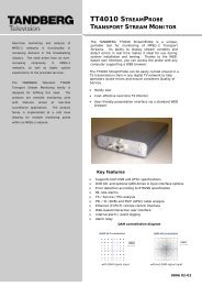
The <strong>antennas</strong> rotate in azimuth and offer a wide elevation scan using ERA’s unique and patented <strong>scanning</strong> technologies,<br />
toge<strong>the</strong>r providing near hemispherical coverage, as shown in Figure 1. The technology makes it possible to receive<br />
satellite signals down to just 20° above <strong>the</strong> horizon with no tilting of <strong>the</strong> aperture. This paper describes <strong>the</strong> key features<br />
of <strong>the</strong> different designs and discusses issues relating to alignment and tracking. It also provides measured per<strong>for</strong>mance<br />
<strong>for</strong> some of <strong>the</strong> Ku-Band units that have been manufactured and trialled.<br />
Figure 1: Hybrid electric / mechanical <strong>scanning</strong> technique<br />
2. BENEFITS OF THE HYBRID ANTENNA APPROACH<br />
Hybrid <strong>antennas</strong> have a number of key benefits which make <strong>the</strong>m ideally suited to both commercial and military mobile<br />
applications. First, <strong>the</strong>y are very low <strong>profile</strong>; typically, a Ku-Band antenna has a <strong>profile</strong> of only 100mm, including<br />
positioner and radome. In addition, it is possible to achieve near hemispherical coverage by <strong>scanning</strong> a high gain beam<br />
with low sidelobes, controlled without using expensive electronic phase shifters.
2<br />
ERA has also developed a range of low cost fabrication techniques based on <strong>the</strong> use of injection moulded plastics which<br />
make <strong>the</strong> manufacturing costs comparable to reflectors in high volume applications. The technologies are very rugged<br />
and, because extensive use is made of waveguide technologies, <strong>antennas</strong> can be designed <strong>for</strong> operation anywhere<br />
between X-band and EHF.<br />
3. APPLICATIONS<br />
The technology is being targeted at <strong>the</strong> following applications:<br />
• Commercial automotive. Supporting live satellite TV broadcasts while on <strong>the</strong> move.<br />
• High Speed train. Supporting RX-only and two way web-based services available to passengers <strong>for</strong> business<br />
and infotainment.<br />
• Aeronautical. Combining <strong>the</strong> low <strong>profile</strong> of a phased array with <strong>the</strong> economics of a reflector, providing<br />
airline passengers with internet access on long haul flights.<br />
• Military mobile terminals. Providing up-to-<strong>the</strong>-minute tactical and logistical in<strong>for</strong>mation via satellite to <strong>the</strong><br />
battlefield.<br />
4. A RANGE OF TECHNICAL SOLUTIONS<br />
ERA is developing three variants of its hybrid antenna technology.<br />
4.1 Single polarisation antenna<br />
This solution is based on an array of travelling wave waveguide radiators. A number of waveguides are fed from a<br />
common input and each has a longitudinal slot cut in one broad wall. Energy leaks from <strong>the</strong>se slots and radiates in a<br />
direction which depends on <strong>the</strong> internal dimensions of <strong>the</strong> waveguides. ERA has patented a unique technology <strong>for</strong><br />
varying <strong>the</strong> geometry of <strong>the</strong> waveguide without incurring high losses, making it possible to scan <strong>the</strong> beam in elevation<br />
between about 20° and 70° with respect to <strong>the</strong> horizon over an operating bandwidth of up to about 10%; <strong>the</strong> elevation<br />
beam exhibits some differential scan with frequency over this band. Using <strong>the</strong> continuously radiating aperture, <strong>the</strong><br />
spurious grating lobes often suffered by conventional arrays are eliminated, resulting in excellent radiation pattern<br />
characteristics, as shown below.<br />
Patterns at 12.45GHz<br />
40<br />
35<br />
24.5°<br />
38.0° 51.0°<br />
66.1°<br />
30<br />
25<br />
20<br />
Gain (dBi)<br />
15<br />
10<br />
5<br />
Position 1<br />
Position 2<br />
Position 3<br />
Position 4<br />
0<br />
-5<br />
-10<br />
-90 -67.5 -45 -22.5 0 22.5 45 67.5 90<br />
Angle<br />
Figure 2: Typical elevation patterns of low <strong>profile</strong> antenna<br />
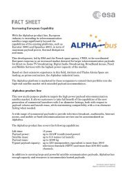
ERA has developed its first Ku-Band product, illustrated below, based on this design approach, using an external<br />
polariser which can be configured to receive ei<strong>the</strong>r hand of circular polarisation. The antenna is only 125mm high.
3<br />
4.2 Dual polarisation antenna<br />
Figure 3: Antenna <strong>for</strong> TV reception on <strong>the</strong> move<br />
ERA has also demonstrated a solution <strong>for</strong> simultaneous dual linear polarisations. This antenna provides co-located<br />
beams with horizontal and vertical polarisations using no external polariser. It uses a much simpler radiating structure<br />
which is even lower <strong>profile</strong> than <strong>the</strong> first generation design. The generation of dual linear polarisations makes this<br />
solution particularly appropriate to European applications. In addition, because it is possible to realise different designs<br />
without <strong>the</strong> need to develop very costly production tooling, it is ideally suited to lower volume requirements such as a<br />
rail application.<br />
The design uses an alternative elevation scan technology based on changing <strong>the</strong> propagation constants of two hybrid<br />
waveguide modes in a parallel plate travelling wave beam<strong>for</strong>ming structure. These generate horizontal and vertical<br />
polarised signals which radiate with variable elevation scan angle. Since <strong>the</strong>re is no external polariser in <strong>the</strong> design, <strong>the</strong><br />
<strong>profile</strong> can be reduced to less than 100mm in Ku-Band, or 75mm in Ka-Band. O<strong>the</strong>r polarisations, as might be required<br />
to compensate <strong>for</strong> <strong>the</strong> polarisation twist which occurs when <strong>the</strong> satellite is not due south of <strong>the</strong> mobile, can be achieved<br />
by appropriate combination of <strong>the</strong> linear signals at RF or IF. This dual polarisation antenna again covers <strong>the</strong> scan range<br />
20° to 70° but has an extended operating bandwidth of up to about 20%. Once more, <strong>the</strong>re is some differential scan<br />
over <strong>the</strong> frequency band.<br />
A proof of concept breadboard antenna, shown in Figure 4 below, has been manufactured and has demonstrated colocated<br />
vertically and horizontally polarised radiation. Development is continuing and it is anticipated that production<br />
<strong>antennas</strong> operating in Ku-Band will be available at <strong>the</strong> end of 2005.
4<br />
Figure 4: Dual polarised Breadboard Antenna<br />
0<br />
-10<br />
-10<br />
-20<br />
-20<br />
dB<br />
-30<br />
dB<br />
-30<br />
-40<br />
-40<br />
-50<br />
-50<br />
-60<br />
-90 -60 -30 0 30 60 90<br />
Deg<br />
-60<br />
-90 -60 -30 0 30 60 90<br />
Deg<br />
Vertical Polarisation<br />
Horizontal Polarisation<br />
Figure 5: Elevation patterns of breadboard antenna (<strong>the</strong>ory vs measurement)<br />
4.3 Broadband TX/RX antenna<br />
ERA’s most recent development offers full duplex operation, with both transmit and receive functions being provided<br />
from a common aperture. Azimuth mechanical rotation is retained. A novel, dual polarised, broadband radiating<br />
aperture has been designed, combining printed and waveguide components, which ensures grating-lobe free patterns<br />
over an extended elevation scan range from zenith to 20° with respect to <strong>the</strong> horizon. The bandwidth has been extended<br />
to 25%, making it possible to cover <strong>the</strong> band from 11.7 – 14.5GHz with a single aperture. The antenna incorporates<br />
independent selection of <strong>the</strong> elevation scan angle in transmit and receive, making it possible to co-locate TX and RX<br />
beams, a feature not available using <strong>the</strong> antenna configurations described above.<br />
This configuration provides dual linear polarisations in both bands which can be combined at RF or IF to create any<br />
o<strong>the</strong>r arbitrary polarisation, including circular polarisation. The TX/RX antenna, shown in Figure 6 below, also has a<br />
<strong>profile</strong> of about 100mm at Ku-Band.
5<br />
Figure 6: Aeronautical common aperture TX/RX antenna<br />
Prototype development of this antenna is currently underway, aimed at an aeronautical application. The first<br />
demonstration unit will be available in early 2005.<br />
5. TYPICAL KU-BAND SPECIFICATIONS<br />
The table below summarises <strong>the</strong> typical specifications that can be achieved. These are all based on a nominal<br />
requirement <strong>for</strong> an antenna with about 9dB/K worst case G/T at an elevation angle of 20° with respect to <strong>the</strong> horizon.<br />
Antennas can be designed to have different gain and G/T values, if required.<br />
Table 1: Typical specifications<br />
Single polarised design Dual polarised design Dual band design<br />
Frequency band 12.2-12.7GHz 10.7 – 12.7GHz 11.7-12.7GHz (RX)<br />
14-14.5GHz (TX)<br />
Antenna size 22” x 22” (560 x 560mm) 22” x 22” (560 x 560mm) 26” x 26” (640 x 640mm)<br />
Diameter 820mm (32”) 820mm (32”) 960mm (38”)<br />
Height (inc radome and 125mm (5”) 100mm (4”) 100mm (4”)<br />
positioner)<br />
Azimuth scan range 360° 360° 360°<br />
Elevation scan range 20° to 70° 20° to 70° 20° to 90°<br />
(from horizon)<br />
Gain @ 20° above <strong>the</strong><br />
horizon<br />
>30dBi >30dBi >30dBi (RX)<br />
>31dBi (TX)<br />
G/T @ 20° above <strong>the</strong> 9dBK 9dBK 9dBK<br />
horizon<br />
Polarisation Single CP (switchable) Dual linear Dual linear<br />
6. MANUFACTURING TECHNOLOGIES<br />
ERA’s low <strong>profile</strong> antenna technologies can be realised using CNC machined aluminium alloy parts or metallised<br />
plastic or metal mouldings. The use of plastics can provide <strong>the</strong> potential <strong>for</strong> significantly reduced mass, as well as very<br />
low manufacturing costs.<br />
ERA’s first generation automotive antenna product is manufactured from six high precision injection moulded parts.<br />
These use a premium grade glass-filled plastic which has similar mechanical properties to aluminium, both in terms of
6<br />
operating temperature range and stability, and mechanical strength. The parts are moulded and <strong>the</strong>n plated using an<br />
electroless copper plating process. Extensive validation of <strong>the</strong> processes has been undertaken to ensure that <strong>the</strong>y are<br />
suited to <strong>the</strong> harsh environments found in outdoor environments worldwide.<br />
The moulding process can produce repeatable parts up to about 700mm square with a tolerance of typically 25µm over<br />
<strong>the</strong> complete part. Excluding <strong>the</strong> initial cost of production tooling, and assuming a large production run, it is possible to<br />
manufacture a complete set of parts <strong>for</strong> <strong>the</strong> antenna <strong>for</strong> a few hundred Euros.<br />
Figure 7: Moulded plastic first generation low <strong>profile</strong> antenna<br />
7. SATELLITE ACQUISITION AND TRACKING<br />
The low <strong>profile</strong> <strong>antennas</strong> may be married to a sophisticated tracking system which combines use of <strong>the</strong> received satellite<br />
signal and on-board sensors. Initial acquisition is generally achieved by detecting a satellite ID code. By having prior<br />
knowledge of <strong>the</strong> satellites that are visible from <strong>the</strong> operating location, it is possible to achieve very rapid acquisition by<br />
identifying <strong>the</strong> first satellite that is detected, calculating <strong>the</strong> offset of <strong>the</strong> wanted satellite, and moving rapidly to this<br />
wanted transponder. Once acquired, tracking is maintained by mechanically di<strong>the</strong>ring <strong>the</strong> antenna and monitoring signal<br />
strength.<br />
If <strong>the</strong> satellite signal is lost, on-board sensors maintain <strong>the</strong> required look direction if <strong>the</strong> vehicle is moving, allowing<br />
immediate re-acquisition when <strong>the</strong> satellite becomes visible again. Rapid re-acquisition can take place while <strong>the</strong> onboard<br />
sensors remain sufficiently stable. Such sensors tend to drift with time, and <strong>the</strong> quality of <strong>the</strong> sensors used<br />
determines how long <strong>the</strong> satellite can be out of view be<strong>for</strong>e <strong>the</strong> full acquisition sequence must be initiated.<br />
When transmit <strong>antennas</strong> are included in <strong>the</strong> system, TX beam pointing is achieved by slaving <strong>the</strong> TX and RX <strong>antennas</strong><br />
toge<strong>the</strong>r.<br />
8. CONCLUSIONS<br />
For mobile <strong>satcom</strong> applications covering a wide range of markets, low <strong>profile</strong> hybrid <strong>antennas</strong> provide an excellent<br />
compromise between <strong>the</strong> high costs of phased arrays and <strong>the</strong> high <strong>profile</strong> of a reflector.<br />
ERA is developing design solutions which meet a wide range of operational requirements and, because <strong>the</strong>y use low<br />
loss technologies, can be readily scaled to meet future requirements in bands ranging from X-Band to SHF.