Wheel balancer machine for trucks, bus and car wheels with manual ...
Wheel balancer machine for trucks, bus and car wheels with manual ...
Wheel balancer machine for trucks, bus and car wheels with manual ...

Create successful ePaper yourself
Turn your PDF publications into a flip-book with our unique Google optimized e-Paper software.
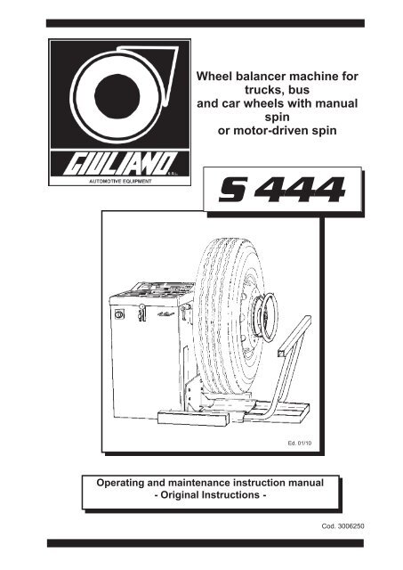
<strong>Wheel</strong> <strong>balancer</strong> <strong>machine</strong> <strong>for</strong><br />
<strong>trucks</strong>, <strong>bus</strong><br />
<strong>and</strong> <strong>car</strong> <strong>wheels</strong> <strong>with</strong> <strong>manual</strong><br />
spin<br />
or motor-driven spin<br />
S 444<br />
Ed. 01/10<br />
Operating <strong>and</strong> maintenance instruction <strong>manual</strong><br />
- Original Instructions -<br />
Cod. 3006250
DECLARATION DE CONFORMITE CE<br />
CE DECLARATION OF CONFORMITY<br />
DICHIARAZIONE DI CONFORMITA CE<br />
CE - ÜBEREINSTIMMUNG<br />
DECLARACIÓN CE DE CONFORMIDAD<br />
GIULIANO S.p.A. - Via Guerrieri, 6 - 42015 Correggio (RE) ITALY<br />
dichiara sotto la propria esclusiva responsabilità che il prodotto:<br />
declare on our own responsibility that the product:<br />
Déclare sous son propre responsabilité que le produit:<br />
erklärt unter ihrer eigenen Verantwortung, daß das Erzeugnis:<br />
declara bajo su exclusiva responsabilidad que el producto:<br />
Equilibratrice Balancer Equilibreuse Auswuchtmaschine<br />
Equilibradora<br />
S 444<br />
Matricola<br />
al quale questa dichiarazione si riferisce E' CONFORME ALLE SEGUENTI DIRETTIVE:<br />
to which declaration refers is in con<strong>for</strong>mity <strong>with</strong> the FOLLOWING DIRECTIVES:<br />
au quel cette déclaration se rapporte EST CONFORME AUX DIRECTIVES SUIVANTES:<br />
darauf diese Erklärung Bezug nimmt, mit den folgenden Bestimmungen übereinstimmt:<br />
2006/42/CE - 2006/95/CE - 2004/108/CE<br />
ed alle Norme:<br />
as well as to the following norms:<br />
ainsi qu’aux normes suivantes:<br />
und folgender Vorschrift gemäß:<br />
EN 12100-1:2005 - EN 13850:2007 - EN 61000-6-3:2007 - EN 12100-2:2005 -<br />
EN 7731:2009 - EN 61000-6-1:2007 - EN 294:1993 - EN 60204-1:2006 -<br />
EN 61000-6-4:2007 - EN 349:2008 - EN 60439-1:2000 - EN 61000-6-2:2006<br />
Il firmatario della presente dichiarazione è la persona autorizzata a costituire il fascicolo tecnico<br />
The signer of this declaration of con<strong>for</strong>mity is the person authorized to provide <strong>for</strong> the technical file literature<br />
Le signataire de cette déclaration de con<strong>for</strong>mité est la personne autorisée à produire le dossier technique<br />
Der Unterzeichner dieser CE-Übereinstimmung ist dazu ermächtigt, das technische Aktenbündel vorzulegen<br />
El firmante de esta declaración es la persona autorizada para elaborar el expediente técnico<br />
Correggio, 07/01/2010<br />
Il modello della presente dichiarazione è con<strong>for</strong>me alla Norma EN ISO/IEC 17050-1<br />
The model of present declaration is in con<strong>for</strong>mity <strong>with</strong> directive EN ISO/IEC 17050-1<br />
Le modèle de cette déclaration est con<strong>for</strong>me à la Norme EN ISO/IEC 17050-1<br />
Das Modell dieser Erklärung übereinstimmt mit der Bestimmung EN ISO/IEC 17050-1<br />
El modelo de esta afirmación está en consonancia con la norma EN ISO/IEC 17050-1<br />
GIULIANO S.p.A<br />
Il Presidente<br />
G. Maselli
DICHIARAZIONE DI CONFORMITA’ RAEE<br />
RAEE DECLARATION OF CONFORMITY<br />
DECLARATION DE CONFORMITE RAEE<br />
RAEE - ÜBEREINSTIMMUNG<br />
GIULIANO S.p.A. - Via Guerrieri, 6<br />
- 42015 Correggio (RE) ITALY<br />
dichiara sotto la propria esclusiva responsabilità che il prodotto:<br />
declare on our own responsibility that the product:<br />
Déclare sous son propre responsabilité que le produit:<br />
erklärt unter ihrer eigenen Verantwortung, daß das Erzeugnis:<br />
Equilibratrice ruote<br />
Equilibreuse de roue<br />
<strong>Wheel</strong>-<strong>balancer</strong><br />
Radauswuchtmaschine<br />
al quale questa dichiarazione si riferisce E’ CONFORME ALLA DIRETTIVA:<br />
to which declaration refers is in con<strong>for</strong>mity <strong>with</strong> the FOLLOWING DIRECTIVE:<br />
au quel cette déclaration se rapporte EST CONFORME À LA DIRECTIVES SUIVANTES:<br />
darauf diese Erklärung Bezug nimmt, mit der folgenden Bestimmungen<br />
übereinstimmt:<br />
2002/96/CE e 2003/108/CE (RAEE)<br />
Raccolta differenziata<br />
Specific garbage collection<br />
Collecte sélective<br />
getrennte Müllsammlung<br />
La presente macchina/apparecchiatura rientra nelle prescrizioni della Direttiva 2002/96/CE e 2003/108/CE (RAEE) e non può essere smaltita<br />
come rifiuto urbano generico ma attraverso raccolta separata; Il simbolo del bidone barrato riportato sul prodotto indica questa prescrizione.<br />
Lo smaltimento della stessa e dei suoi componenti dovrà avvenire secondo quanto previsto dalle Direttive 2002/96/CE e<br />
2003/108/CE (RAEE) e le disposizioni di Legge del Paese di destinazione della macchina/apparecchiatura; il mancato<br />
rispetto della direttiva è sanzionabile secondo le disposizioni di Legge del Paese di dstinazione.<br />
L’abb<strong>and</strong>ono o smaltimento non corretto delle macchine/apparecchiature sottoposte alla Direttiva 2002/96/CE può<br />
provo<strong>car</strong>e gravi danni all’ambiente ed alle persone.<br />
Il costruttore è disponibile, ai sensi della Direttiva, allo smaltimento della macchina/apparecchiatura; per questo servizio contattare il costruttore<br />
o i rivenditori autorizzati secondo il Paese di destinazione della macchina/apparecchiatura.<br />
This equipment is subject to the regulations <strong>for</strong>eseen by Directives 2002/96/CE <strong>and</strong> 2003/108/CE (RAEE) <strong>and</strong><br />
there<strong>for</strong>e it cannot be scrapped as a generic scrap material but through specific collection circuits; the symbol <strong>with</strong><br />
“barred tank” marked on the product refers to this prescription.<br />
Scrapping must be made in accordance <strong>with</strong> Directives 2002/96/CE <strong>and</strong> 2003/108/CE (RAEE) as well as <strong>with</strong> the<br />
local Regulations in <strong>for</strong>ce in the Country of installation, the non-respect of the Directive is subject to sanctions<br />
according to the national Laws of the Country of destination.<br />
Ab<strong>and</strong>onment or wrong scrapping of the equipment subject to Directive 2002/96/CE can cause serious damage to<br />
the environment.<br />
The manufacturer is available, according to the Directive, to scrap the equipment; <strong>for</strong> this service, please contact<br />
the manufacturer or your dealer.<br />
Ce produit rentre dans les prescriptions des Directives 2002/96/CE et 2003/108/CE (RAEE) et il ne peut donc pas<br />
être mis à la ferraille comme du matériel générique mais à travers un circuit de collecte sélective; le symbole du<br />
« bidon barré » reproduit sur la <strong>machine</strong> se réfère à cette prescription.<br />
Le traitement de la <strong>machine</strong> et de ses composants devra se réaliser en con<strong>for</strong>mité aux Directives 2002/96/CE et<br />
2003/108/CE (RAEE) ainsi qu’aux dispositions de Loi en vigueur dans le Pays de destination de la <strong>machine</strong>, le non-respect de la<br />
Directive est passible de sanctions par rapport aux Lois nationales du Pays de destination.<br />
L’ab<strong>and</strong>on ou un traitement erroné des produits sujets à la Directive 2002/96/CE peut provoquer de graves dégâts à<br />
l’environnement.<br />
Le constructeur est disposé, aux termes de la Directive, à s’occuper du traitement de la <strong>machine</strong>; pour ce service contacter le<br />
constructeur ou les revendeurs autorisés.<br />
Die vorliegende Maschine/Gerät fällt in den Vorschriften der 2002/96/CE Richtlinie, und kann nicht<br />
als allgemeiner Stadtmüll sondern durch getrennte Müllsammlung beseitigt werden; das Symbol<br />
mit der durchgestrichenen Mülltonne weist auf diese Vorschrift hin.<br />
Die Entsorgung des Gerätes und seiner Best<strong>and</strong>teilen muss nach den 2002/96/CE und 2003/108/CE<br />
(RAEE) Richtlinien und nach den Vorschriften des Bestimmungsl<strong>and</strong>es der Maschine/Gerätes<br />
erfolgen, die Nicht-Beachtung der Vorschrift ist sanktionierbar laut dem Gesetz des Bestimmungsl<strong>and</strong>es<br />
Die unkorrekte Entsorgung oder Verlassen der zu der 2002/96/CE vorgelegenen Richtlinie Maschine/<br />
Gerätes kann die Umwelt und die Personen schwer beschädigen.<br />
Gemäß der Richtlinie, steht der Hersteller für die Entsorgung der Maschine/Gerätes zur Verfügung;<br />
dazu setzen Sie sich mit dem Hersteller oder mit den berechtigten Händlern nach dem<br />
Bestimmungsortes der Maschine/Gerätes in Verbindung.<br />
Correggio, 01/07/06
0123<br />
1 - DESCRIPTION OF THE BALANCING MACHINE<br />
1.1 - GENERAL<br />
The <strong>machine</strong> is designed <strong>for</strong> precision balancing of truck, <strong>bus</strong> <strong>and</strong> <strong>car</strong>s <strong>wheels</strong>, weighing up to 200 Kg.<br />
The <strong>machine</strong> is complete <strong>with</strong> a built-in pneumatic lift mounted on castors in order to facilitate clamping of<br />
the wheel on the adapter <strong>and</strong> to ensure greater mounting accuracy.<br />
Technical features<br />
· <strong>Wheel</strong> spinning is powered by a single phase electric motor <strong>and</strong> is actuated by shifting a lever which<br />
moves the driver pulley in contact <strong>with</strong> the driven pulley <strong>and</strong> then presses the START push-button.<br />
· Pad type brake operated by the very same spinning lever displaced to the opposite direction.<br />
· Brake can be locked <strong>for</strong> easier wheel mounting.<br />
· Measurement can be made <strong>with</strong> any speed of rotation, there<strong>for</strong>e it is not necessary to wait to reach a<br />
preset speed.<br />
· The amount of unbalance <strong>and</strong> relative position are shown on digital displays after just one measuring<br />
spin.<br />
· Easy selection of static balancing only or <strong>for</strong> balancing light alloy <strong>wheels</strong> of unusual shape (1 STATIC<br />
function <strong>and</strong> 2 ALU functions). Furthermore, the unique ALU S function allows calibration to be per<strong>for</strong>med<br />
<strong>for</strong> special light alloy <strong>wheels</strong> <strong>with</strong> direct presetting of the measurements.<br />
· Self-calibration of the <strong>machine</strong> can be easily <strong>and</strong> quickly <strong>car</strong>ried out <strong>with</strong> any wheel, even if not balanced.<br />
1.2 - TECHNICAL DATA<br />
⎯ Max wheel weight...............................................................................200 Kg<br />
⎯ Max power consumption....................................................................500W<br />
⎯ St<strong>and</strong>ard power supply.......................................................................230 V single phase (or 115 V)<br />
⎯ Balancing accuracy............................................................................1 gr<br />
⎯ Min/max balancing speeds.................................................................42/120 r.p.m.<br />
⎯ Rim diameter......................................................................................from 10" to 26" or from 255 to 660 mm<br />
⎯ Rim width............................................................................................from 1.5" to 20" or from 40 to 510 mm<br />
⎯ Cycle time...........................................................................................8 to 20 sec<br />
⎯ Net weight..........................................................................................210 Kg<br />
⎯ Overall dimensions of <strong>machine</strong>..........................................................1880 x 840 x h = 970<br />
⎯ Sound pressure level in cycle.............................................................< 70 d B (A)<br />
⎯ Operating temperature range.............................................................from 0 to 50° C<br />
⎯ Min/max compressed air pressure (LIFT)..........................................from 8 to 10 Kg/cm² ~ 0,8 ÷ 1Mpa<br />
................................................................................................................8 ÷ 10 BAR; ~ 115 ÷ 145 PSI<br />
- UNBALANCE DISPLAY PITCH:<br />
CARS = 5 g (0.25 oz)<br />
TRUCKS = 50 g (1 oz)<br />
When FINE (END) is pressed, the unbalance is displayed <strong>with</strong> pitch: 1 g <strong>for</strong> CARS<br />
10 g <strong>for</strong> TRUCKS<br />
- UNBALANCE DISPLAY THRESHOLD:<br />
CARS = 5 g (.3 Oz)
5<br />
CONTENTS<br />
PAGE<br />
1 - DESCRIPTION OF THE BALANCING MACHINE...........................................................................................................4<br />
1.1 - GENERAL.........................................................................................................................................................4<br />
1.2 - TECHNICAL DATA............................................................................................................................................4<br />
1.3 - USER RECOMMENDATIONS..........................................................................................................................5<br />
1.4 - STANDARD SAFETY DEVICES.......................................................................................................................5<br />
2 - HOISTING AND INSTALLATION.....................................................................................................................................5<br />
3 - POWER SUPPLY.............................................................................................................................................................5<br />
4 - PNEUMATIC CONNECTION ...........................................................................................................................................6<br />
5 - ADAPTER MOUNTING....................................................................................................................................................6<br />
6 - WHEEL MOUNTING........................................................................................................................................................6<br />
7 - CONTROL PANEL...........................................................................................................................................................7<br />
8 - PRESETTING OF DIMENSIONS.....................................................................................................................................8<br />
8.1 - OPTIONS..........................................................................................................................................................9<br />
8.2 - PRESETTING WITH GAUGE EXTENSION.....................................................................................................9<br />
9 - WHEEL BALANCING......................................................................................................................................................10<br />
9.1 - MEASUREMENT OF UNBALANCE.................................................................................................................10<br />
9.2 - RECALCULATION OF UNBALANCE...............................................................................................................10<br />
9.3 - STATIC - ALU....................................................................................................................................................11<br />
9.4 - "ALU S" SPECIAL FUNCTION..........................................................................................................................12<br />
10 - SELF-CALIBRATION.....................................................................................................................................................13<br />
10.1 - FOR CAR AND TRUCK WHEELS..................................................................................................................13<br />
10.2 - FOR TRUCK WHEELS ONLY.........................................................................................................................13<br />
11 - ERRORS.........................................................................................................................................................................14<br />
11.1 - INCONSISTENT UNBALANCE READINGS...................................................................................................14<br />
12 - ROUTINE MAINTENANCE............................................................................................................................................15<br />
12.1 - REPLACEMENT OF FUSES..........................................................................................................................15<br />
12.2 - REPLACEMENT OF DRIVER PULLEY..........................................................................................................15<br />
12.3 - TO REPLACE THE BRAKE PAD....................................................................................................................15<br />
13 - RECOMMENDED SPARE PARTS LIST........................................................................................................................16
0123<br />
TRUCKS = 50 g (2 Oz)<br />
1.3 - RECOMMENDATIONS<br />
- Be<strong>for</strong>e starting to use the balancing <strong>machine</strong>, <strong>car</strong>efully read the operating instruction <strong>manual</strong>.<br />
- Keep the <strong>manual</strong> in a safe place <strong>for</strong> future reference.<br />
- Refrain from removing or modifying <strong>machine</strong> parts which would impair correct operation. Please<br />
get in touch <strong>with</strong> the technical Service when needing repairs.<br />
- Do not use strong jets of compressed air <strong>for</strong> cleaning.<br />
- Use alcohol to clean plastic panels or shelves (AVOID LIQUIDS CONTAINING SOLVENTS).<br />
- Be<strong>for</strong>e starting the wheel balancing cycle, make sure that the wheel is securely locked on the<br />
adapter.<br />
- The <strong>machine</strong> operator should not wear clothes <strong>with</strong> flapping edges; make sure that unauthorized<br />
personnel do not approach the <strong>machine</strong> during the work cycle.<br />
- Avoid placing counterweights or other bodies in the base which could impair the correct operation<br />
of the balancing <strong>machine</strong>.<br />
- The balancing <strong>machine</strong> should not be used <strong>for</strong> purposes other than those described in the instruction<br />
<strong>manual</strong>.<br />
- It is <strong>for</strong>bidden to use wheel locking devices other than those approved by the manufacturer. It is<br />
also <strong>for</strong>bidden to balance objects other than vehicle <strong>wheels</strong>.<br />
Caution: if the <strong>machine</strong> is left idle <strong>for</strong> more than two minutes, the system automatically<br />
switches off all displays <strong>and</strong> the LEDs, apart from the <strong>car</strong>/truck selector LED which<br />
stats flashing. To return to normal operation conditions, press any push-button or<br />
move the wheel.<br />
1.4 - STANDARD SAFETY DEVICES<br />
- Low speed of rotation<br />
- Protection on LIFT control.<br />
2 - HOISTING AND INSTALLATION<br />
To hoist the <strong>machine</strong>, lever the base only <strong>with</strong> the 3 support points. Under no circustances apply<br />
<strong>for</strong>ce to other points such as spindle, head or accessory shelf.<br />
Check that the balancing <strong>machine</strong> rests on the floor at the three points. There is no need to anchor the<br />
<strong>machine</strong> to the floor <strong>for</strong> correct operation.<br />
3 - POWER SUPPLY<br />
WARNING: Electrical connection must be made by specialized personnel.<br />
Connection to the single phase mains must be between phase <strong>and</strong> neutral <strong>and</strong> under<br />
no circumstances between phase <strong>and</strong> earth. Earthing is essential <strong>for</strong> correct <strong>machine</strong><br />
operation.<br />
The firm declines all responsibility <strong>and</strong> warranty in the event of incorrect connection.<br />
Be<strong>for</strong>e connecting the <strong>machine</strong> to the mains through the relative cable, check that the mains voltage matches<br />
that shown on the nameplate at the back of the balancing <strong>machine</strong>. Rating of the electrical connection<br />
should be on the basis of the <strong>machine</strong> electrical power consumption (see nameplate).<br />
- The <strong>machine</strong> mains supply cable should be fitted <strong>with</strong> a plug complying <strong>with</strong> current regulations.<br />
- It is advisable to provide the <strong>machine</strong> <strong>with</strong> its own electrical connection incorporating a suitable circuit<br />
breaker. Connection to the mains should be through a slow acting safety switch rated at 4A (230V) or<br />
10A (115V).<br />
- When connection is made directly to the main control panel, <strong>with</strong>out using any plug, it is advisable to<br />
padlock the main switch of the balancing <strong>machine</strong> so that its use is limited only to authorized personnel.
4 - PNEUMATIC CONNECTION<br />
Connection to the pneumatic system is on the back of the balancing <strong>machine</strong>. Adjustment can be <strong>car</strong>ried<br />
out according to lifting <strong>and</strong> lowering requirements. The pneumatic system has been studied so that great<br />
movement "elasticity" is provided to the lift in any position of its stroke. In this way, the position of the<br />
wheel can be adjusted according to requirements <strong>and</strong> <strong>with</strong> minimum <strong>manual</strong> ef<strong>for</strong>t. Max input pressure 10<br />
Kg/cm 2 ( ~ 10 BAR; 145 PSI; ~ 1 MPa) adjusted through a pressure switch.<br />
7<br />
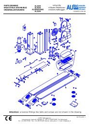
5 - ADAPTER MOUNTING<br />
Fig. 1<br />
The wheel <strong>balancer</strong> is supplied complete <strong>with</strong><br />
cone type adapter <strong>for</strong> fastening <strong>wheels</strong> <strong>with</strong> central<br />
bore. Other optional adapters can be mounted:<br />
a) Remove threaded end piece A after backing off<br />
screw B.<br />
b) Mount the new adapter (see enclosed brochures)<br />
6 - WHEEL GUARD ASSEMBLY AND ADJUSTMENT<br />
Assembly the components in the order indicated in the specific exploded drawing.<br />
The guard position can be adjusted using the appropriate screw. Adjust the angular position of ring 6 so<br />
that the wheel enters the relative seat when the guard is closed.
0123<br />
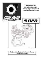
7 - CONTROL PANEL<br />
Fig. 2<br />
1 = Digital display, AMOUNT OF UNBALANCE, inside<br />
2 = Digital display, AMOUNT OF UNBALANCE, outside<br />
3 = Indicator, POSITION OF UNBALANCE, inside<br />
4 = Indicator, POSITION OF UNBALANCE, outside<br />
5 = Indicators, correction mode selected<br />
6 = Push-button <strong>for</strong> selecting STATIC/DYNAMIC - g/ounce - mm/inch; self-calibration<br />
7 = Push-button, recalculation <strong>and</strong> self-calibration<br />
8 = Push-button, correction mode selection, ALU<br />
9 = Push-buttons, <strong>manual</strong> DISTANCE input<br />
10 = Push-buttons, <strong>manual</strong> WIDTH input<br />
11 = Push-buttons, <strong>manual</strong> DIAMETER input<br />
12 = Push-button, <strong>car</strong> selection<br />
13 = Push-button, truck selection<br />
14 = Indicators, <strong>car</strong> - truck selection<br />
15 = Threshold push-button<br />
N.B.: Press buttons only <strong>with</strong> the fingers. Do not use the counterweight pincers or other pointed objects.
9<br />
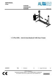
8 - PRESETTING OF DIMENSIONS<br />
FIG. 3 : DIAMETER<br />
- Preset the nominal diameter shown on the tyre<br />
FIG. 4: WIDTH<br />
- Preset the nominal width which is generally given on the rim, or else measure width " b " <strong>with</strong> the gauge<br />
supplied.<br />
FIG. 5: DISTANCE<br />
- Preset distance " a " of the inside of the rim.<br />
8.1 - OPTIONS
0123<br />
PRESETTINGS MEMORIZED ALSO WITH INOPERATIVE MACHINE:<br />
+<br />
+<br />
F ↑ a ↓ a<br />
<br />
- UNIT of measurement of unbalance grams/ounces<br />
PRESETTINGS LOST WHEN MACHINE IS SWITCHED OFF:<br />
F<br />
F<br />
+<br />
or<br />
+<br />
↑ b<br />
↓ b<br />
<br />
- UNIT OF MEASUREMENT OF WIDTH mm/inch<br />
(from "PRESETTING OF DIMENSIONS"<br />
by selecting WIDTH)<br />
N.B.: in inches each time the <strong>machine</strong> is switched on.<br />
F<br />
+<br />
or<br />
↑ d<br />
<br />
- UNIT OF MEASUREMENT OF DIAMETER mm/inch<br />
(from "PRESETTING OF DIMENSIONS"<br />
by selecting DIAMETER).<br />
N.B.: In inches each time the <strong>machine</strong> is switched on.<br />
F<br />
+<br />
↓ d<br />
DISPLAY OF UNBALANCE:<br />
F<br />
ALU<br />
Dynamic Static Dynamic<br />
<br />
<br />
ALU1 ALU2 ALUS ALU1<br />
8.2 - PRESETTING WITH GAUGE EXTENSION<br />
The extension increases the distance measuring range of the gauge by 10 cm (fig. 5A).<br />
Proceed as follows:<br />
- Insert the extension on the distance gauge.<br />
- Measure the distance as already described in the above procedures.<br />
- After reading value “a” on the scale, return the gauge to 0 <strong>and</strong> preset the value “a + 10” in <strong>manual</strong><br />
mode.<br />
- Preset the diameter <strong>and</strong> width in <strong>manual</strong> mode as already illustrated.
11<br />
9 - WHEEL BALANCING<br />
9.1 - MEASUREMENT OF UNBALANCE<br />
a) The spinning of the wheel is motorized. Move the special motor control lever upwards. When displays<br />
go out, release the control. The driving <strong>for</strong>ce is disengaged <strong>and</strong> the motor stops.<br />
b) Measurement can be made at any speed as soon as the wheel stops accelerating.<br />
c) When the displays show the values, brake the wheel by acting on the lever in the opposite sense of<br />
spinning (Wait at least 2 seconds be<strong>for</strong>e a new spin). Displays 1 <strong>and</strong> 2 show the amount of unbalance.<br />
Displays 3 <strong>and</strong> 4 indicate through LEDs the correction position. When all the LEDs light up, it means<br />
that the correction weight should be placed at the top in the vertical position.<br />
FIG. 6: CORRECTION ON THE OUTSIDE<br />
FIG. 7: CORRECTION ON THE INSIDE<br />
9.2 - RECALCULATION OF THE UNBALANCE<br />
- Preset the new dimensions following the procedures described above.<br />
- Without repeating the spin, press<br />
C<br />
- The new recalculated unbalance values are displayed.
0123<br />
9.3 - STATIC - ALU<br />
(Balancing of motorcycle <strong>wheels</strong>, in light alloy or unusually shaped)<br />
CAUTION: <strong>for</strong> a correct operation, the wheel to be balanced must be mounted on an adapter <strong>for</strong><br />
<strong>car</strong> <strong>wheels</strong>. Calibrate the <strong>machine</strong> following the procedure described in section 8.<br />
Functions available can be selected from the measurement control panel <strong>and</strong> permit the displaying of<br />
correction weights in different positions <strong>with</strong> respect to normal positions.<br />
Press push-button [F] or [ALU] <strong>and</strong> select the required function, (see 8.1). For each function, the microprocessor<br />
processes <strong>and</strong> displays the real values of the compensation weights corrected on the basis of<br />
the correction weight position.<br />
FIG. 8<br />
NORMAL - Balancing of steel or light alloy rims<br />
by applying clip-on weights on the rim<br />
edges.<br />
STATIC - STATIC correction is required <strong>for</strong><br />
motorcycle <strong>wheels</strong> or when it is not<br />
possible to place the counterweights<br />
on both sides of the rim.<br />
ALU 1 - Balancing of light alloy rims <strong>with</strong> application<br />
of adhesive weights on the rim<br />
shoulders.<br />
ALU 2 - Balancing of alloy rims <strong>with</strong> hidden<br />
application of the outer adhesive<br />
weight.<br />
The position of the outer weight is<br />
indicated in the figure.
9.4 - SPECIAL "ALU S" FUNCTION<br />
This function is used <strong>for</strong> unusually shaped alloy rims where ALU2 is not able to guarantee sufficient accuracy.<br />
- Select the S option by pressing the push-button [ALU] (LEDs ALU1 - ALU 2 both light up together).<br />
- Measure the sizes according to the following scheme:<br />
13<br />
Sequence:<br />
a) To modify al press<br />
b) To modify aE press<br />
c) To modify dl press<br />
N.B.: dE is = 0.8 dl by default<br />
d) To modify dE press<br />
Attention: by selecting dl the system automatically resets dE = 0.8 dl<br />
The system automatically calculates the distance between the centre of gravity of the two weights by<br />
considering the width of the weights to be approx. 14 mm. To display the unbalance associated <strong>with</strong> the<br />
preset dimensions, press the push-button [C]; the system will automatically proceed to recalculate the<br />
unbalance, otherwise per<strong>for</strong>m the new spin.<br />
If it is not possible to insert the gauge into the rim (13”-14” <strong>car</strong> <strong>wheels</strong>), measure aI <strong>and</strong> aE <strong>with</strong> a precision<br />
ruler.<br />
It is often possible to take measurements using the gauge extension (8.2).
0123<br />
For <strong>machine</strong> self-calibration, proceed as follows:<br />
10 - SELF-CALIBRATION<br />
10.1 - FOR CAR AND TRUCK WHEELS<br />
1 Fit a medium-sized metal <strong>car</strong> wheel on the shaft. Example: 6" x 14" (± 1")<br />
2 Preset the exact dimensions of the wheel mounted. Caution!! Presetting of incorrect dimensions<br />
can mean the <strong>machine</strong> is not correctly calibrated <strong>and</strong> ther<strong>for</strong>e all subsequent measurements will be<br />
incorrect until a new self-calibration is per<strong>for</strong>med <strong>with</strong> the correct dimensions!<br />
F<br />
3 First press push-button . While keeping it pressed, press also until the positioning<br />
LEDs pass from flashing to being steady.<br />
4 Release the push-buttons <strong>and</strong> turn the wheel until all displays go out. Then wheel can be released.<br />
(The self-calibration spin can also require a couple of minutes. It is important not to knock the<br />
wheel during this spin or else accelerate again after being released, otherwise it is not possible<br />
to per<strong>for</strong>m the self-calibration <strong>and</strong> the <strong>machine</strong> will stop <strong>with</strong> an error message).<br />
5 At the end of the first spin, the following message appears on the display "Add 100 (Add 3.5)" while<br />
the outside positioning LEDs flash. At this point add a weight of 100 grams (3.5 oz) on the OUTSI-<br />
DE in any angular position.<br />
6 Again bring the wheel up to speed (until the display "Add 100" goes out). Likewise this spin can require<br />
a couple of minutes. Leave the wheel to rotate freely until the wording "END CAL" appears.<br />
At the end of this operation, the <strong>machine</strong> will be calibrated. Remove the master weight from the<br />
wheel <strong>and</strong> <strong>with</strong> a new spin proceed to balance the mounted wheel.<br />
The values measured by the <strong>machine</strong> <strong>with</strong> self-calibration cycle are automatically memorized in a special<br />
memory which retains them even when the <strong>machine</strong> is switched off. Hence when the <strong>machine</strong> is switched<br />
on again, it is ready to operate correctly. However, self-calibration can be <strong>car</strong>ried out whenever required<br />
or when there is some doubt whether the <strong>machine</strong> is operating correctly.<br />
C<br />
10.2 - USE FOR TRUCK WHEEL ONLY<br />
It does not matter whether <strong>car</strong> <strong>wheels</strong> (if <strong>car</strong> adapter is available) or truck <strong>wheels</strong> are used. With truck<br />
<strong>wheels</strong>, it is recommended to preset the wheel dimensions <strong>with</strong> great <strong>car</strong>e especially the width <strong>and</strong> distance<br />
to be referred to the centre of gravity of the counterweight to be applied.<br />
The procedure is identical to that described <strong>for</strong> <strong>car</strong> <strong>wheels</strong>, except <strong>for</strong>:<br />
1) Select "truck <strong>wheels</strong>"<br />
2) At the end of the first spin, add a master weight of 350 grams (12 oz).
15<br />
11 - ERRORS<br />
Various fault conditions may arise during <strong>machine</strong> operation. If detected by the microprocessor, they<br />
appear on the display <strong>with</strong> the message "ERR:" followed by a number <strong>with</strong> one of the meanings listed<br />
below:<br />
ERROR<br />
MEANING<br />
1 Could be caused by a faulty position transducer, or something preventing the<br />
wheel from turning or else too slow speed of rotation.<br />
2 During the measurement spins, wheel speed had drop to below minimum (90<br />
r.p.m. <strong>for</strong> CARS - 42 r.p.m. <strong>for</strong> TRUCKS).<br />
3 <strong>Wheel</strong> unbalance too high or incorrect calibration.<br />
4 <strong>Wheel</strong> turning in opposite direction.<br />
7 Faulty self-calibration values.<br />
8 Error during self-calibration. Could be due to the second spin made <strong>with</strong>out<br />
adding reference weight, or else by a break in the transducer cable.<br />
Further error indications are given by the LED "ALU2" during measurement.<br />
When the wheel has been brought up to speed, a rapid flashing of this LED means the speed of rotation<br />
is too high; the <strong>machine</strong> will wait <strong>for</strong> the speed to fall, LED ALU2 will go out <strong>and</strong> the measurement will be<br />
made.<br />
If during the measuring spin there is a r<strong>and</strong>om flashing of the above LED, the system is in a dwell status,<br />
probably due to a knock received by the <strong>machine</strong>. However, the measurement is repeated automatically<br />
<strong>with</strong>out errors. Errors in balancing can be due to rubbing of the reduction gear on the spindle gear. After<br />
spinning the wheel, always allow the crank h<strong>and</strong>le to return to rest position.<br />
11.1 - INCONSISTENT UNBALANCE READINGS<br />
Sometimes after balancing a wheel <strong>and</strong> removing it from the balancing <strong>machine</strong>, then again mounting it<br />
on the balancing <strong>machine</strong>, it is found that the wheel is not balanced.<br />
This does not depend on incorrect indication of the <strong>machine</strong>, but only on a faulty mounting of the wheel<br />
on the adapter, i.e. in the two mountings, the wheel has assumed a different position <strong>with</strong> respect to the<br />
balancing <strong>machine</strong> shaft centre line.<br />
If the wheel is mounted on the adapter <strong>with</strong> screws, it could be possible that the screws have not correctly<br />
tightened - they should be tightened one by one crosswire or else (as often happens) holes have been<br />
drilled on the wheel <strong>with</strong> too wide tolerances.<br />
Small errors, up to 10 grams (4 oz) are to be considered normal in <strong>wheels</strong> locked by a cone; the error is<br />
normally greater <strong>for</strong> <strong>wheels</strong> locked <strong>with</strong> screws or studs.<br />
If, after balancing, when the wheel is refitted on the vehicle, it is still out-of-balance, this could be due to<br />
unbalance of the <strong>car</strong> brake drum or very often due to the holes <strong>for</strong> the screws of the rim <strong>and</strong> drum drilled<br />
sometimes <strong>with</strong> too wide tolerances. In such case a readjustment could be dvisable using the balancing<br />
<strong>machine</strong> <strong>with</strong> the wheel mounted.
0123<br />
12- ROUTINE MAINTENANCE<br />
(Non specialized personnel)<br />
WARNING: Be<strong>for</strong>e <strong>car</strong>rying out any operation, disconnect the <strong>machine</strong> from the mains.<br />
12.1 - TO REPLACE THE FUSES<br />
Remove the weight holder shelf to gain access to the power supply PC board <strong>and</strong> the two fuses mounted<br />
on this board. Should replacement be required, use fuses of the same current rating. If the failure persists,<br />
contact the Technical Service Department.<br />
12.2 - REPLACEMENT OF DRIVER PULLEY<br />
- Remove the weight holder shelf being <strong>car</strong>eful not to pull on the electrical cables.<br />
- Untight the pulley mounting screw <strong>and</strong> change the pulley.<br />
12.3 - TO REPLACE THE BRAKE PAD<br />
Back-off the two screws fastening the worn brake pad to the motor mounting brake. Securely fix the new<br />
brake pad by tightening the screws.<br />
NONE OF THE OTHER MACHINE PARTS REQUIRE MAINTENANCE.
17<br />
13 - LIST OF RECOMMENDED SPARE PARTS<br />
(references on the exploded drawings)<br />
CODE<br />
DESCRIPTION<br />
182185730 Balancing spring<br />
07FG33406<br />
Rubber covered driving pulley<br />
42FB37113<br />
Complete brake pad<br />
020620803 Bearing 6208-2Z Ø 40/80/18<br />
67M38954M<br />
Position pick-up board c/w cable <strong>and</strong> plug<br />
86SB44557<br />
Cable <strong>with</strong> microstart<br />
181270080 Spring, rim distance gauge<br />
050144103 Display panel<br />
940603137 Complete power plate 230/115V<br />
511231002 Switch KL 1002 + Q 555<br />
86PR36224<br />
Complete panel<br />
86SC36223<br />
Computer board<br />
611018463 Trans<strong>for</strong>mer 115/230 - 9/9<br />
940512124 Supply board<br />
681002000 Fuses DM 5x20 2A<br />
162368905 Pneumatic control 368-905<br />
181198630 Spindle spring<br />
SPECIAL PARTS FOR 230V MACHINES<br />
568001458 Capacitor 14MF 450V Faston screw M8<br />
SPECIAL PARTS FOR 115V MACHINES<br />
568003558 Capacitor 35MF 450V Faston screw M8
0123<br />
SPECIAL MAINTENANCE<br />
(Only <strong>for</strong> specialized personnel)<br />
14 - TO CHANGE SUPPLY VOLTAGE<br />
- Always check the required voltage on the <strong>machine</strong> nameplate.<br />
- St<strong>and</strong>ard power supply 220 - 240 V / 50 Hz single phase.<br />
- For 115 V power supply, the components must be replaced as indicated in the attached exploded<br />
drawing.<br />
15 - SELECTING OF MACHINE PARAMETERS<br />
To preset the <strong>machine</strong> parameters (DF; I; S), press push-buttons <strong>and</strong> as in<br />
self-calibration. When the position LEDs stop flashing, instead of per<strong>for</strong>ming the spin, press the following<br />
push-buttons <strong>with</strong>in 5 seconds <strong>and</strong> in the correct sequence:<br />
[ ↓ a ] then [ ↑ a ] then [ F ]<br />
After pressing [ ↓ a ] <strong>and</strong> [ ↑ a ], the displays go out. After pressing [ F ], the current value of " DF " appears;<br />
it can be modified <strong>with</strong> [ ↑ b ] <strong>and</strong> [ ↓ b].<br />
Press [ ↑ a ] to modify parameter " I ". The current value (in %) appears on the right display, while the<br />
wording "in" <strong>and</strong> the symbol " ⎯ " appear on the left display if the correction is negative or else " " if it<br />
is positive. Modify <strong>with</strong> [ ↑ b ] <strong>and</strong> [ ↓ b ]. Press [ ↑ a ], the value of parameter " S " appears on the right<br />
display; modify <strong>with</strong> [ ↑ b ] <strong>and</strong> [↓ b]. To finish, press [ ↑ a ].<br />
N.B.: when [ FINE ] is pressed during any one of the parameter presetting phases, the system interrupts<br />
such function <strong>and</strong> sets the parameters <strong>with</strong> basic values.<br />
After modifying such values, the <strong>machine</strong> requires self-calibration again.<br />
CAUTION! The basic configuration values: " DF "= 120<br />
" I " = +0<br />
" S " = 330<br />
The values at which the <strong>machine</strong> is factory set are given on a special nameplate inside the <strong>machine</strong>.<br />
F<br />
C
16 - CHECKING OF THE RIM DISTANCE GAUGE<br />
Check that the ruler used <strong>for</strong> measuring the DISTANCE of the <strong>wheels</strong> reads 26.5 cm as measurement of<br />
the distance from the adapter plane. If the graduated scale is changed, position it <strong>with</strong> the line indicating<br />
26.5 at the fixed index limit (reading point) when the gauge tip coincides <strong>with</strong> the adapter plane.<br />
Fig. 10<br />
19<br />
Reading point :26.5 cm<br />
Adapter plane<br />
17 - ASSEMBLY TO THE PIEZO MEASURES<br />
Problems of excessive compensation <strong>and</strong> out-of-phase sometimes depends on a fault in the piezo measurers.<br />
To replace them, proceed as follows:<br />
1. Remove the weight shelf.<br />
2. Remove nuts 1 <strong>and</strong> 2 <strong>with</strong> relative cup springs<br />
<strong>and</strong> washers.<br />
3. Back-off screws 3, 4 <strong>and</strong> 5 then disassemble the<br />
various parts.<br />
4. Reassemble the various parts <strong>with</strong>out tightening<br />
the nuts being <strong>car</strong>eful to follow the correct sequence.<br />
N.B. Mount the piezo units in accordance <strong>with</strong> the<br />
position of the coloured wires shown in the drawing.<br />
5. Keeping the spindle perfectly aligned, tighten nut<br />
5 <strong>with</strong> a spanner, <strong>and</strong> nuts 3 <strong>and</strong> 4 by h<strong>and</strong> (by half<br />
a turn <strong>with</strong> the spanner if necessary).<br />
6. Refit the washers, cup springs <strong>and</strong> nuts 1 <strong>and</strong><br />
2. Tighten the nuts fully in order to fully regain the<br />
elasticity of the cup springs, then loosen them by half<br />
a turn. This will automatically ensure correct preloading<br />
on the piezo (a torque wrench can be used set<br />
to 400 kg. cm.).<br />
7. Cover the piezo units <strong>with</strong> a generous layer of<br />
silicone.<br />
(N.B. For correct operation, insulation of the piezo<br />
crystals should be greater than 50 Mohm).<br />
8. Reassemble the various parts.<br />
9. Again <strong>car</strong>ry out the automatic calibration.<br />
yellow<br />
blue<br />
yellow<br />
white<br />
Fig. 11
0123<br />
18 - LOGIC TROUBLE SHOOTING SEQUENCE<br />
When PC boards require replacement, repeat the self-calibration operation after having again preset the<br />
<strong>machine</strong> parameters.
0123<br />
19.1 - CHECKING AND SETTING OF STATIC VALUE (STI)<br />
(To be per<strong>for</strong>med <strong>with</strong> <strong>car</strong> wheel of average size)<br />
Carry out self-calibration<br />
<strong>Wheel</strong> balancing.<br />
Tolerance 1 gram.<br />
Select STATIC.<br />
Apply 100 grams on inside.<br />
Per<strong>for</strong>m the spin.<br />
Is the STATIC value on<br />
the inside between 98 <strong>and</strong><br />
102 grams?<br />
YES<br />
NO<br />
Select function "SELECTING OF<br />
MACHINE PARAMETERS".<br />
Increase value "I" if the inside STATIC<br />
value is too low, decrease if it is too<br />
high (2 digits of "I" are equivalent to<br />
approx. 1 gram).<br />
END
23<br />
19.2 - CHECKING AND SETTING OF UNBALANCE POSITION<br />
(To be per<strong>for</strong>med <strong>with</strong> <strong>car</strong> wheel of average size)<br />
Carry out self-calibration<br />
<strong>Wheel</strong> balancing.<br />
Tolerance 1 gram.<br />
Apply weight of 100 grams<br />
on the outside.<br />
Per<strong>for</strong>m the spin.<br />
Is the 100 gram<br />
counterweight in the six<br />
o'clock position?<br />
NO<br />
Select function "SELECTING OF MA-<br />
CHINE PARAMETERS".<br />
Modify value "S" by making various<br />
attempts ("S" is expressed in degrees)<br />
YES<br />
END
0123<br />
19.3 - CHECKING AND CALIBRATION OF FIXED DISTANCE VALUE (DF)<br />
(Per<strong>for</strong>m <strong>with</strong> <strong>car</strong> wheel of average size)
20 - WHEEL MEASUREMENT AND PRESETTING ON THE BA-<br />
LANCING MACHINES<br />
25<br />
The ever increasing need <strong>for</strong> more accurate calibration <strong>and</strong> use of the ALU functions means that it is<br />
important to establish how to measure the rims <strong>and</strong> how the balancing <strong>machine</strong> interprets the preset data.<br />
Hence a description is now given of how to modify the preset dimensions automatically in order to obtain<br />
the distances of the correction planes which are defined as through planes <strong>for</strong> the centres of gravity of<br />
the corrective weights. Consider a typical rim: size "l", given as width by the rim manufacturer, differs from<br />
the measurement of the distance between the correction planes <strong>for</strong> the rim thickness <strong>and</strong> physical dimensions<br />
of the counterweight, whose centre of gravity is located at distance “h” from the resting point of<br />
the rim edge. The balancing <strong>machine</strong> automatically corrects the measurement preset by adding 2 x h = 6<br />
mm to the measurement. Measurement “b” made <strong>with</strong> the gauge is generally more accurate even if very<br />
similar to the measurement "l" known to the rim user. The two measurements differ only by the thickness<br />
of the sheet metal, usually about 2 mm per side. Such insignificant distance means that an accurate<br />
calibration can be obtained regardless of whether the inner rim <strong>with</strong> "l" or outer width “b” is preset. It is a<br />
good rule to add ¼ inch to the value given by the manufacturer. As regards the ALU functions, the <strong>machine</strong><br />
per<strong>for</strong>ms the following approximations in addition to the systematic correction regarding the centre of<br />
gravity of the counterweight as seen above.<br />
ALU 1
0123<br />
21 - HOW TO CHECK FUNCTIONING AND ACCURACY<br />
Further to some notices in<strong>for</strong>ming us of defects <strong>and</strong> unaccuracies not clearly traceable, we are explaining<br />
hereunder the procedure how to check functioning <strong>and</strong> accuracy to help us to detect problems.<br />
FIRST CHECKS<br />
Accurate wiping of adapter <strong>and</strong> cones<br />
Spring cover sliding<br />
Shaft end blocking<br />
CALIBRATION (see 10)<br />
Use the wheel indicate<br />
Set accurate measures, in <strong>manual</strong> mode if necessary<br />
Make self-calibration<br />
CHECKING MACHINE CALIBRATION<br />
Make 10 spins <strong>with</strong>out loosening the wheel <strong>and</strong> detect MAX oscillations<br />
F.I. (Inner side)= F.E. (Outer side)= (tolerance ± 2)<br />
Put 100 gr. on FE first <strong>and</strong> then on FI using an accurately balanced wheel) Detect rates<br />
F.I.= F.E.= POS.E.= F.I.= F.E.= POS.I=<br />
(tolerance 3%)<br />
CHECKING THE ADAPTER<br />
Turn a fine balanced wheel upside down (180°) <strong>and</strong> detect unbalance rates<br />
ERR.MAX =<br />
This check-out in particular must be made <strong>with</strong> a sample wheel whose max unbalance errors due to<br />
centering are well known (generally lower than 10 gr. <strong>for</strong> iron <strong>wheels</strong>).<br />
SCRAPPING<br />
Attention! For a correct waste disposal, consult the declaration of con<strong>for</strong>mity to RAEE <strong>and</strong> ROHS (where applicable)<br />
MAINTENANCE<br />
At the achievement of 5 years from the date of installation <strong>and</strong> commissioning, the product must be reviewed<br />
in its entirety
0123 0123<br />
GIULIANO S.P.A.<br />
Via Guerrieri, 6 - 42015 CORREGGIO (RE) ITALY<br />
Tel. +39 0522 731.111 - Fax +39 0522 633.109<br />
http://www.giuliano.it<br />
E-Mail: giuliano@giuliano.it