Chip Scale Review - July 2007
Chip Scale Review - July 2007
Chip Scale Review - July 2007

You also want an ePaper? Increase the reach of your titles
YUMPU automatically turns print PDFs into web optimized ePapers that Google loves.
<strong>Chip</strong><strong>Scale</strong><br />
www.<strong>Chip</strong><strong>Scale</strong><strong>Review</strong>.com<br />
®<br />
r e v i e w<br />
<strong>July</strong> <strong>2007</strong><br />
• Lead-Free One Year After<br />
• Wafer Bumping
See us at SEMICON West, Booth #7358
CONTENTS<br />
The International Magazine of <strong>Chip</strong>-<strong>Scale</strong><br />
Electronics, Flip-<strong>Chip</strong> Technology, Optoelectronics<br />
Interconnection and Wafer-Level Packaging<br />
<strong>July</strong> <strong>2007</strong><br />
Volume 11, Number 5<br />
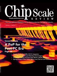
THE COVER<br />
It’s time again for your humble cover scribe to apply<br />
his flying fingers to the keyboard and tell you about our<br />
magnificent <strong>July</strong> issue. By now, you have correctly identified<br />
the Golden Gate Bridge on our cover, (opened in 1937),<br />
which has become an icon for San Francisco, current home<br />
of SEMICON West. At the time, it was painted with a red<br />
lead primer and a lead-based topcoat. Far ahead of RoHS,<br />
the bridge scraped the lead off in 1965 and applied a zinc<br />
silicate primer and an acrylic topcoat of Sherwin Williams’<br />
“International Orange.” The bridge’s conversion from lead<br />
to lead-free provides an outstanding segue into mention of<br />
the article by my favorite editor, Ron Iscoff. I just peeked at<br />
his article that looks at RoHS one year after. You don’t want<br />
to miss it! If you don’t know what RoHS is by this time,<br />
please confine your reading in future to Sports Illustrated<br />
or Playboy! Is RoHS merely an exercise in futility by a<br />
bunch of silly, frustrated Europeans with nothing better to<br />
do than munch on their braunschweigers and pate de fois<br />
gras, while hoisting a Heineken? La plume de ma tante—I<br />
don’t know! But I am pleased to refer you to Terry<br />
Thompson’s article and column. Terry is our senior editor<br />
and our “go-to” guy for MEMS. Don’t miss “MEMS the<br />
Word!” or his article on wafer-bumping tools and services.<br />
There is so much good stuff in this issue to tell you about,<br />
and so little space, that I’m beside myself with angst!<br />
See you at SEMICON West!<br />
(Illustration for <strong>Chip</strong> <strong>Scale</strong> <strong>Review</strong> by<br />
Design 2 Market) [design2marketinc.com]<br />
<strong>Chip</strong> <strong>Scale</strong> <strong>Review</strong>, at 7291 Coronado Dr., Suite 8, San Jose, CA 95129<br />
(ISSN 1526-1344), is published eight times a year, with issues in<br />
January-February, March, April, May-June, <strong>July</strong>, August-September,<br />
October and November-December.<br />
Periodical postage paid at San Jose, Calif., and additional offices.<br />
POSTMASTER: Send address changes to <strong>Chip</strong> <strong>Scale</strong> <strong>Review</strong> magazine,<br />
7291 Coronado Dr., Suite 8, San Jose, CA 95129.<br />
COVER FEATURES<br />
RoHS a Year After: Too Little, Too Late; 36<br />
Too Much, Too Soon—or Just Right?<br />
Ron Iscoff, Editor<br />
It’s been a year since RoHS became the hottest electronics industry buzzword<br />
since Chlorofluorocarbons. Although the European Union earmarked<br />
six hazardous substances for elimination in electronics, clearly the removal<br />
of lead from electronics was closest to the hearts of the EU commission.<br />
Where has RoHS gone? We’ll tackle that subject now.<br />
Wafer-Bumping Processes, Tools and Trends<br />
Terrence E. Thompson, Senior Editor<br />
Wafer bumping continues to make inroads into the IC packaging<br />
mainstream. As it does, the technology opens Pandora’s box: Should I<br />
bump my own wafers or send them to an experienced contractor?<br />
What technology should I use for bumping? This article might help<br />
you decide.<br />
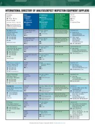
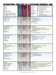
International Directory of Wafer-Bumping Services<br />
<strong>Chip</strong> <strong>Scale</strong> <strong>Review</strong> Staff<br />
Single Device Tracking: A Cost-Benefit Analysis<br />
Dave Huntley, KINESYS Software<br />
42<br />
50<br />
55<br />
The acceptance and implementation of single device tracking has been<br />
made much easier with the release of SEMI standard E142. This article<br />
discusses how, when and why to implement this new standard on the<br />
assembly floor.<br />
Advances in Wafer Plating: Meeting the Next 61<br />
Challenge of Through-Silicon-Via Processing<br />
Bob Forman, Rohm and Haas Electronic Materials<br />
Copper electroplating has become a standard in electronics for making<br />
electrical interconnects between devices. A new packaging technology,<br />
using through-silicon-vias employs copper plating for high-density<br />
packaging at wafer level through chip stacking.<br />
Handling and Processing Technologies Utilized 69<br />
In a High-Volume Manufacturing Environment<br />
Stefan Pargfrieder, Paul Lindner, Steven Dwyer<br />
and Thorsten Matthias, EV Group<br />
As semiconductor manufacturers continue to squeeze the thickness<br />
of devices and wafers down, new and disruptive methods to meet the<br />
manufacturing challenges associated with new products and processes<br />
have to be utilized.<br />
CONTINUED >><br />
<strong>Chip</strong> <strong>Scale</strong> <strong>Review</strong> ■ <strong>July</strong> <strong>2007</strong> ■ [<strong>Chip</strong><strong>Scale</strong><strong>Review</strong>.com] 1
The roadmap to opportunity<br />
starts here<br />
Electrolytic Wafer Bumping<br />
Electrolytic Copper<br />
Stop by our Semicon West booth<br />
for an opportunity to win a GPS<br />
© Rohm and Haas Electronic Materials, <strong>2007</strong>. InterVia, Solderon, Rohm and Haas, and Rohm<br />
and Haas Electronic Materials are trademarks of Rohm and Haas Company or its affiliates.<br />
Photoimageable Dielectric<br />
Opportunity::: We know you are faced with immense challenges on your technology roadmap.<br />
Our suite of InterVia and Solderon products and processes provides you with the opportunity to meet<br />
your biggest challenges. We bring the most advanced materials technology, innovative processes,<br />
improved reliability and environmentally-friendly solutions for your most demanding wafer-level<br />
packaging applications:<br />
■<br />
■<br />
■<br />
Dielectrics for WLCSP and redistribution<br />
Electrolytic copper for through silicon<br />
vias, redistribution and seed layers<br />
Thick resists for wafer bumping<br />
■<br />
■<br />
Electrolytic low-alpha tin and lead-free<br />
processes for wafer bumping<br />
Electroplating metals for UBM<br />
The roadmap to opportunity starts here…<br />
please visit us at Semicon West, booth #8533, West Hall, Level 2 to find out more.<br />
www.rohmhaas.com
CONTENTS<br />
FEATURE ARTICLES<br />
Projection Scanning: Not a New Kid on the Block<br />
Jim Sooy<br />
75<br />
What’s the best photolithography tool for<br />
your wafer-level packaging applications? In<br />
this article we’ll take a close look at projection<br />
scanning and compare it to 1:1 wafer<br />
steppers and proximity alignment systems.<br />
From Cow <strong>Chip</strong>s to Silicon <strong>Chip</strong>s: Setting-Up a WLP 87<br />
Microfabrication Facility Far from the Infrastructure<br />
Fred Haring, Bernd Scholz, Syed Sajid Ahmad and Aaron<br />
Reinholz, Center for Nanoscale Science and Engineering,<br />
North Dakota State University<br />
Setting up a modern facility for wafer-level<br />
fabrication, chip-scale packaging and<br />
surface mount technology far from the center<br />
of semiconductor activity entails tough<br />
challenges and careful planning. This article<br />
relates some of the good, the bad and the<br />
Quasimodo-ugly experiences faced by the<br />
NDSU staff.<br />
Did You Know? <strong>Chip</strong> <strong>Scale</strong> <strong>Review</strong> is now offered in a<br />
digital format with a powerful search engine!<br />
DEPARTMENTS<br />
Publisher’s Letter Gene Selven<br />
Another great year For SEMICON and us!<br />
Assembly Lines Ron Iscoff<br />
Software radio: can you hear me now?<br />
MEMS the Word! Terrence E. Thompson<br />
What packaging hurdles do MEMS face?<br />
Electronic Trends Steve Berry and Sandra Winkler<br />
Wafer-level packaging with a twist<br />
Industry News<br />
Profile: TTS Group (Advertorial)<br />
Product Showcase (Advertisement)<br />
What’s New!<br />
Inside Patents A. Jason Mirabito and Carol Peters<br />
How to file patents (and fight patents) without tears!<br />
Calendar<br />
Ad Index/More News/Sales Offices<br />
4<br />
7<br />
9<br />
13<br />
15<br />
80<br />
81<br />
82<br />
85<br />
99<br />
104<br />
<strong>Chip</strong> <strong>Scale</strong> <strong>Review</strong> ■ <strong>July</strong> <strong>2007</strong> ■ [<strong>Chip</strong><strong>Scale</strong><strong>Review</strong>.com] 3
PUBLISHER’S LETTER<br />
Another Great Year<br />
For SEMICON and Us!<br />
By Gene Selven, Publisher [gselven@aol.com]<br />
The SEMICON West exposition in San Francisco this year will feature 1300<br />
exhibitors—including <strong>Chip</strong> <strong>Scale</strong> <strong>Review</strong>. During the show, we’ll distribute<br />
thousands of extra copies of this magazine to show visitors from our booth,<br />
W2-8717, and from racks in Moscone Center’s West Hall.<br />
Forgive us for tooting our own horn, but our SEMICON West issue—the one you’re<br />
reading right now—has about 25 percent more advertisers than we carried in last<br />
year’s show issue!<br />
We’ve mailed about 26,000 copies, and our digital edition will be read by an estimated<br />
additional 10,000 people worldwide.<br />
By the way, did you know that <strong>Chip</strong> <strong>Scale</strong> <strong>Review</strong> is the leading magazine for the IC<br />
assembly and packaging community? What do we mean by “leading”?<br />
• More editorial pages on an issue-by-issue basis than our nearest competitor.<br />
• More staff-written editorial pages on an issue-by-issue basis, more than twice as many!<br />
• More advertising pages in every issue—and this is where the “rubber meets the<br />
road” for a publication, since it shows the faith our advertisers have placed in us!<br />
• Two key editors with a combined total of 50 years in the semiconductor industry,<br />
creating a magazine of editorial excellence!<br />
The company that publishes the number two magazine in the field has 40 other magazines<br />
in such areas as oil and gas, dentistry, graphic arts, electrification, etc., plus a multitude<br />
of conferences in those areas.<br />
We have one magazine, this one; a newsletter, The TUESDAY REPORT; and one conference,<br />
our International Wafer-Level Packaging Conference in September. We don’t have to worry<br />
about what the corporate nabobs in Tulsa want. The buck stops right here—with me.<br />
Decisions are made in Silicon Valley, the capitol of semiconductor technology since the beginning.<br />
We’re dedicated to publishing the best magazine for IC assembly and packaging<br />
available. That is our continuing goal, and that is our mission. And our advertisers and<br />
readers, by making us #1, have shown that we’re succeeding.<br />
Report from ECTC<br />
I recently returned from the 57th Electronic Components and Technology Conference<br />
(ECTC) in Reno, Nevada.<br />
ECTC continues to be a “must-see” conference that provides a dynamic environment<br />
for learning, discussion and networking the technology.<br />
We were, by the way, the only publication whose publisher was on site. We spoke to<br />
about 60 exhibitors, many of whom will also be at SEMICON West.<br />
Our congratulations to the ECTC participants and staff for an outstanding event! i<br />
4<br />
<strong>Chip</strong> <strong>Scale</strong> <strong>Review</strong> ■ <strong>July</strong> <strong>2007</strong> ■ [<strong>Chip</strong><strong>Scale</strong><strong>Review</strong>.com]<br />
VOLUME 11, NUMBER 5<br />
The International Magazine of <strong>Chip</strong>-<strong>Scale</strong><br />
Electronics, Flip-<strong>Chip</strong> Technology, Optoelectronic<br />
Interconnection and Wafer-Level Packaging<br />
STAFF<br />
Gene Selven Publisher<br />
7291 Coronado Dr., Ste. 8, San Jose, CA 95129<br />
b 408.996.7016 > 408.996.7871<br />
gselven@aol.com<br />
Ron Iscoff Editor & Associate Publisher<br />
929 Ebbetts Ave., Manteca, CA 95337<br />
b 209.824.1289 > 209.644.7747<br />
chipscale@gmail.com<br />
Terrence Thompson Senior Editor<br />
2303 Randall Rd. #140, Carpentersville, IL 60110<br />
b 847.515.1255<br />
tethompson@aol.com<br />
Steve Berry Contributing Editor<br />
b 408.369.7000 > 408.369.8021<br />
saberry@electronictrendpubs.com<br />
Dr. Tom Di Stefano Contributing Editor<br />
b 408.399.4501 > 408.395.0448<br />
tom@centipedesystems.com<br />
Dr. Subash Khadpe Contributing Editor<br />
skhadpe@semitech.com<br />
Harvey S. Miller Contributing Editor-at-Large<br />
b 650.328.4550 > 650.327.2360<br />
h.miller@ieee.org<br />
Paul M. Sakamoto Contributing Editor–Test<br />
b 925.924.9110 x148<br />
paul.sakamoto@inovys.com<br />
Sandra Winkler Contributing Editor<br />
b 408.369.7000 > 408.369.8021<br />
slwinkler@electronictrendpubs.com<br />
The Official Publication of the WLCSP Forum<br />
SUBSCRIPTION INQUIRIES<br />
Judy Levin <strong>Chip</strong> <strong>Scale</strong> <strong>Review</strong><br />
7291 Coronado Dr., Ste. 8, San Jose, CA 95129<br />
b 408.996.7016 > 408.996.7871<br />
csrsubs@chipscalereview.com<br />
ADVERTISING PRODUCTION<br />
INQUIRIES<br />
Kim Newman<br />
7291 Coronado Dr., Ste. 8, San Jose, CA 95129<br />
b 408.996.7016 > 408.996.7871<br />
csradv@aol.com<br />
REPRINTS<br />
Kim Newman b 408.996.7016<br />
8 csradv@aol.com<br />
ADVISORS<br />
Mark DiOrio MTBSolutions<br />
Dr. Tom Di Stefano Centipede Systems<br />
Charles R. Harper Technology Seminars Inc.<br />
Mark Murdza Antares Advanced Test Technologies<br />
Dr. Guna Selvaduray San Jose State University<br />
Dr. Thorsten Teutsch Pac Tech<br />
Dr. Dietrich Tönnies SUSS MicroTec AG<br />
Dr. David Tuckerman Tessera Technologies<br />
Professor C.P. Wong Georgia Tech<br />
Copyright © <strong>2007</strong> by Gene Selven & Associates Inc.<br />
<strong>Chip</strong> <strong>Scale</strong> <strong>Review</strong> (ISSN 1526-1344) is a registered trademark<br />
of Gene Selven & Associates Inc. Publishing headquarters are<br />
located at 7291 Coronado Drive, Suite 8, San Jose, CA 95129.<br />
All rights reserved.<br />
<strong>Chip</strong> <strong>Scale</strong> <strong>Review</strong> is published eight times a year.<br />
Subscriptions in the U.S. are available without charge to<br />
qualified individuals in the electronics industry. Subscriptions<br />
outside the U.S. (eight issues) by airmail are $60 per year to<br />
Canada or $60 to other countries. In the U.S., subscriptions<br />
by first class mail are $40 per year.
Semicon booth #7857<br />
let us<br />
qualify<br />
your<br />
samples<br />
Introducing our new Advanced Packaging Laboratory<br />
For the first time in North America—qualify your samples on high-volume production equipment,<br />
not semi-automatic tools.<br />
Our equipment set includes:<br />
• Dispensing<br />
• Au/Au ultrasonic bonders<br />
• ±3μm accuracy flip chip bonders<br />
• Plasma treatment—in-line<br />
• Au stud bump bonders<br />
• High-speed chip mounters<br />
• Printing and reflow<br />
For Process:<br />
• Bumping, dicing, bonding, underfill—then full<br />
analysis with X-Ray, SEM and C-SAM<br />
• Conduct DOE’s on production equipment,<br />
expedite the transition to HVM<br />
For inspection and analysis:<br />
• X-Ray<br />
• SEM<br />
• C-SAM<br />
• Die/Bump Shear Tester<br />
• Goniometer<br />
• Temp/Humidity Cycling Chamber<br />
• IR Scope<br />
• Digital Scope<br />
Panasonic<br />
Factory Solutions Company of America<br />
847-495-6100<br />
PFSAmarketing@us.panasonic.com<br />
panasonicfa.com/lab3/
MicrobondAntec –<br />
the power to keep in touch<br />
Solder pastes, wires and<br />
ribbons for Die-Attach and<br />
Die- & Clip-Attach applications<br />
Please visit us at<br />
Semicon West<br />
San Francisco<br />
Booth 8810<br />
01784 www.aim.de<br />
Umicore AG & Co. KG<br />
Microbond - EPM<br />
Hanau · Singapore · Raleigh<br />
www.microbond.eu<br />
Each problem is different; there are specific<br />
answers to any question and specialists who<br />
know what they are doing for every kind of work.<br />
This is why we focus on two things: individual<br />
solutions and innovative ideas.<br />
In our work it is not the search for patent that<br />
has priority in our work, but rather the conversion<br />
of basic research and skills into reliable, customerspecific<br />
processes. This guarantees our customers<br />
functional products and smooth integration.<br />
However, above all it is a love of detail and<br />
consistent quality management that make<br />
MicrobondAntec products into what they are:<br />
the reliable individual solution for all Die-Attach<br />
and Die- & Clip-Attach applications!<br />
Ask us, because Umicore has the solution for<br />
your problems and with MicrobondAntec,<br />
the right answer.<br />
Umicore: a good joint keeps its promise!
ASSEMBLY LINES<br />
Software Radio: Can You Hear Me Now?<br />
By Ron Iscoff, Editor [chipscale@gmail.com]<br />
Unlike “normal” people,<br />
editors live in issue years.<br />
When it’s May, which it is<br />
now, we’re thinking of <strong>July</strong>. When it’s<br />
August, we’ll be thinking of December,<br />
or earlier or later, depending on when<br />
our next issue is printed.<br />
Too bad everyone doesn’t think like we<br />
do. If they did, no one would ever be late!<br />
When you read this, SEMICON West<br />
will be almost a memory—a good, bad<br />
or indifferent one, depending on your<br />
point of view and your business.<br />
At this point, many of you may be<br />
soaking your feet in Epsom salts as you<br />
wait for your corns and calluses to enjoy<br />
the sweet relief from Moscone’s hard,<br />
concrete floors.<br />
Still Lamented<br />
Even after all these years, I still lament<br />
the loss of the San Mateo County Fairgrounds,<br />
SEMICON West’s original venue<br />
(and one that was only about two miles<br />
from my house).<br />
For my colleagues who are becoming<br />
somewhat long in the tooth like me—<br />
and you know who you are—I have a<br />
pop quiz for you: What “things” were<br />
the buildings at the San Mateo County<br />
Fairgrounds named after? Can you<br />
name four of them? You’ll find the<br />
answers at the bottom of this page.<br />
Sadly, Moscone has taken the easy<br />
way out: The buildings are either North<br />
Hall, South Hall or West Hall.<br />
Last year after the show, I suggested<br />
that the Powers that Be (PtB) at Moscone<br />
rename the halls after famous people. I<br />
suggested “Homer Simpson Hall,”“Spartacus<br />
Hall,” and “Venus de Milo Hall.”<br />
I won’t even go into further details,<br />
since the PtB appear to have disregarded<br />
my well-meaning suggestions.<br />
In my next column, I’ll be thinking<br />
out loud again. And we will both have<br />
benefited because SEMICON West will<br />
be over for another year.<br />
One possible question I will address<br />
may be, “Is SEMICON West now an<br />
antiquated albatross with algae-like<br />
detritus dangling from its oral cavity?”<br />
I hope to see you (or hope I saw you<br />
at Moscone). If not, I guess it was karma.<br />
Sin City Follies<br />
As we reported earlier, APEX has abandoned<br />
The City of the Angels, Los Angeles, for<br />
Las Vegas, the City of What? I’ve been to<br />
Vegas a few times over the years, but I<br />
leave the gambling to my better fraction.<br />
APEX, however, is betting that Vegas<br />
will bring the magic touch to its conference—magic<br />
that’s been on the wane.<br />
Appropos Vegas, as philosophers have<br />
pointed out, you don’t build multimillion-dollar<br />
casinos like New York,<br />
New York or Mandalay Bay from the<br />
contributions of winners!<br />
SEMI itself, which is getting as long<br />
in the tooth as I am, has made guttural<br />
noises from time-to-time about moving<br />
the whole SEMICON West kit-n-kaboodle<br />
to Sin City. From what I understand,<br />
that’s still a possibility over the long<br />
term.<br />
Photo taken at last year’s SEMICON West shows<br />
Homer Simpson Hall (at left, formerly North Hall)<br />
and Venus de Milo Hall (formerly South Hall).<br />
Free for All<br />
Seriously folks, how often do you get<br />
something valuable free? I don’t mean<br />
the samples of Grandma’s Tortilla Dip<br />
that they hand out at Costco while you’re<br />
heading for the bread aisle. I mean something<br />
really good for you!<br />
Well, it’s here now. Dr. Ken Gilleo,<br />
that witty inventor, chemist, litigation<br />
consultant, MEMS<br />
expert, public<br />
speaker, mime,<br />
scrivener, multicoastal<br />
manabout-Rhode<br />
Island and manamong-men<br />
(and<br />
Get your free download these are only a<br />
of Ken Gilleo's book! few of the glowing<br />
descriptions he<br />
uses in his own bio!) will let you download<br />
his latest book, The Day Niagara<br />
Falls Turned Green, free!<br />
Continued on page 101 >><br />
<strong>Chip</strong> <strong>Scale</strong> <strong>Review</strong> ■ <strong>July</strong> <strong>2007</strong> ■ [<strong>Chip</strong><strong>Scale</strong><strong>Review</strong>.com] 7
MEMS THE WORD!<br />
What Packaging Hurdles Do MEMS Face?<br />
By Terrence E. Thompson, Senior Editor [tethompson@aol.com]<br />
Will MEMS (microelectromechanical<br />
systems) play<br />
nice with ICs and what<br />
packaging hurdles lie ahead? Are they<br />
candidates for wafer-level packaging?<br />
Let’s look at the facts:<br />
One of the most exciting, and frustrating,<br />
aspects of grasping the MEMS<br />
market share is the incredible rate of<br />
adoption in dozens, probably hundreds,<br />
of industries. Industry groups such<br />
as the MEMS Industry Group (MIG)<br />
in Pittsburgh, Pa. do an excellent job<br />
of tracking progress.<br />
[memsindustrygroup.org]<br />
A Better MEMS Product<br />
Those incredibly small MEMS, and<br />
their nanoscale NEMS counterparts, are<br />
increasingly fulfilling needs that complement<br />
ICs, not replacing them.<br />
In some cases, ICs were small enough<br />
for many sensor, medical and other<br />
applications, but were in need of equally<br />
Sensors are a major application area for MEMS.<br />
(Bosch Sensortec GmbH)<br />
Continued on page 99 >><br />
<strong>Chip</strong> <strong>Scale</strong> <strong>Review</strong> ■ <strong>July</strong> <strong>2007</strong> ■ [<strong>Chip</strong><strong>Scale</strong><strong>Review</strong>.com] 9
Coat/Develop<br />
Photolithography Clusters<br />
Spin Coating<br />
SSEC 3306/8<br />
Fully Automated<br />
to 8 Process Modules<br />
SSEC 3303/4<br />
Fully Automated<br />
to 4 Process Modules<br />
Hot Plate Bake Processing<br />
Wafer production success comes only through a combination of effective<br />
processes and the systems that implement them. Turn to Solid State<br />
Equipment Corporation, a company committed to process—with precise,<br />
high throughput systems that will maximize your wafer production and<br />
support that optimizes your processing. Contact us to have a system<br />
configured to your specific requirements.<br />
SCARA Robotics<br />
SSEC robotic clusters with Class 1 internal<br />
environment include DSP servo spin<br />
control with dynamic coat dispensing and<br />
dispense pump modulation, to routinely<br />
achieve < 1% uniformity.<br />
Clean Production Capability<br />
SSEC Compliance<br />
SEMI ® S2-0703aE Safety<br />
SEMI S8-0705 Ergonomics<br />
FM 4910 Materials<br />
SECS GEM CCS 200 & 300<br />
CE Marked<br />
ETL Listed<br />
Fluid Recirculation System with Maximum Purity (Patent Pending)<br />
A programmable, in-situ collection ring precisely controls the collection of fluids during processing. The system, with open and closed<br />
positions, maintains the purity of the recirculated fluid. A simple gravity drain system avoids hygroscopic action on chemistry.<br />
Open for Etch Solution Recirculation Closed for Post-etch Cleanup Closed for Final Rinse and Dry
Solvent Strip<br />
Immersion and Single<br />
Wafer Processing<br />
Etch<br />
Uniform, Selective Etching on<br />
Multiple Process Levels<br />
Clean<br />
99% Particle Removal Efficiency at<br />
the 88 nm, 65 nm, and 45 nm Nodes<br />
Solvent Immersion<br />
Backside/Bevel Cleaning<br />
High Velocity Fan Scrub<br />
High Pressure Spray<br />
Spray Etch<br />
Single Wafer Megasonic Scrub<br />
US #6,539,952<br />
High Pressure Needle Dispense<br />
Using only milliliters of solvent per wafer,<br />
SSEC solvent processors combine batch<br />
immersion and single wafer spray technology<br />
in one SEMI ® safety compliant,<br />
dry-in/dry-out system. High pressure sprays<br />
are entirely under closed-loop control<br />
for flow, temperature, and dispense<br />
arm motions.<br />
High Pressure Flow Control<br />
Stream Flow Etch<br />
Whether your wet etch requirements are<br />
for structured wafers, backside/bevel strips,<br />
or wafer thinning, SSEC’s patented tools<br />
achieve more controlled results and substantial<br />
COO reduction, compared to batch<br />
or alternative single wafer systems. SSEC’s<br />
exclusive WaferChek in-situ adaptive<br />
process control ensures an optimum etch<br />
on every wafer.<br />
Rotary PVA Brush Scrub<br />
With advanced single wafer non-contact<br />
and contact cleans, SSEC systems can<br />
be configured exactly to your cleaning<br />
requirements. Using dilute chemistries,<br />
such as SC-1 1:1:300, SSEC cleaning<br />
processors have 99% particle removal<br />
efficiency at the 88 nm, 65 nm, and<br />
45 nm nodes, with 30 nm particle size<br />
in development.<br />
Pressure<br />
SiO 2 Etch<br />
Time<br />
Ti Etch<br />
Cu Etch<br />
Solid State<br />
Equipment Corporation<br />
215-328-0700 • email: info@ssecusa.com<br />
www.ssecusa.com
JCET<br />
Your Next<br />
Packaging Partner<br />
for turnkey services in package design,<br />
wafer bumping and probing, assembly and test!<br />
JCET – China<br />
Tel: +86-510-86853728-21#<br />
E-mail: Mary.Hsu@cj-elec.com<br />
Web: www.cj-elec.com<br />
JCET – USA<br />
Tel: 510-573-3612<br />
E-mail: bli@jcet-us.com<br />
Web: www.cj-elec.com<br />
JCET – Taiwan<br />
Tel: +886-3-5634717<br />
E-mail: climax6@ms65.hinet.net<br />
Web: www.cj-elec.com
ELECTRONIC TRENDS<br />
Wafer-Level Packaging with a Twist<br />
By Steve Berry, Contributing Editor [saberry@electronictrendpubs.com] and<br />
Sandra Winkler, Contributing Editor [slwinkler@electronictrendpubs.com]<br />
Wafer-level packages (WLPs)<br />
are IC packages created on<br />
full wafers, rather than on<br />
individual die. Thus, WLPs have the distinction<br />
of being truly die-sized.<br />
WLPs are ideal for handheld products<br />
which require small form factors and<br />
light weight.<br />
However, because they are die-size,<br />
WLPs are not a standard size. Fortunately,<br />
many handheld products frequently<br />
change the design, which lessens the<br />
impact when the package size shrinks<br />
after a die shrink.<br />
Benefits of a WLP<br />
Given that WLPs are created on the face<br />
of the die, they boast the shortest electrical<br />
path. Because WLPs are a tested part<br />
when completed, the devices can also be<br />
used in modules as known good die.<br />
In addition to excellent electrical performance,<br />
reduced cost is a driving<br />
force behind wafer-level packaging. The<br />
cost for packaging the devices on a<br />
given wafer does not change with the<br />
number of die per wafer; generally, all<br />
processes are additive and subtractive<br />
steps performed with mask steps.<br />
As a result of the benefits of WLPs,<br />
their numbers will continue to grow<br />
rapidly, as illustrated in the figure.<br />
Where Are WLPs Found?<br />
IC products that contain WLPs include<br />
Continued on page 101 >><br />
<strong>Chip</strong> <strong>Scale</strong> <strong>Review</strong> ■ <strong>July</strong> <strong>2007</strong> ■ [<strong>Chip</strong><strong>Scale</strong><strong>Review</strong>.com] 13
innovation<br />
Finding new ways to solve problems—whether it’s new<br />
obstacles that arise or the usual process challenges—<br />
we’re here to offer a unique combination of strengths.<br />
Recent example: our award-winning printable phase change material.<br />
Honeywell’s ongoing research and development in chemistry, metallurgy,<br />
and the processes that bring them together—from our new packaging<br />
R&D facility in Spokane, Washington, to our technology center in Shanghai, China—ensure that<br />
wherever challenges arise, we’ll continue to create solutions that solve them. And as a partner to<br />
most of the top semiconductor houses worldwide, our technology portfolio is consistently at the<br />
forefront of invention, empowering the global leaders of innovation. Honeywell Electronic Materials—<br />
helping the manufacturers of today navigate the future.<br />
Contact Honeywell for solutions to your puzzle…<br />
visit www.honeywell.com/sm/em or call 1-408-962-2000.<br />
© <strong>2007</strong> Honeywell International Inc. All rights reserved.
INDUSTRY NEWS<br />
Singapore’s Flextronics to Acquire<br />
Solectron, Milpitas, for $3.6 Billion<br />
Singapore—The shrinking world of EMS<br />
providers will become smaller still with the<br />
proposed acquisition of giant Solectron,<br />
Milpitas, Calif., by competitor Flextronics,<br />
Singapore.<br />
The acquisition has already been approved<br />
by both boards. Flextronics will pay $3.6<br />
billion, based on the June 1 closing price of<br />
the company’s common stock.<br />
SEMICON West XXXVII<br />
Our Annual Rite-of-Passage<br />
‘Glory Days’ Are Gone!<br />
“No surprise there! The glory days of non-<br />
Asia-based EMS companies such as<br />
Solectron are long gone,” said Dr. Subash<br />
Khadpe, president of the Semiconductor<br />
Technology Center, Neffs, Pa., responding<br />
to the acquisition news.<br />
“The future is with Hon Hai Precision<br />
(Foxconn), Flextronics, et al.”<br />
Continued on page 17 >><br />
Panasonic’s Grand Opening<br />
Was Truly a First-of-Its-Kind<br />
Buffalo Grove, Ill.—Attendance exceeded<br />
160 on June 7, when the doors opened to<br />
Panasonic’s new Advanced Packaging Lab<br />
for Microelectronics, a significant event<br />
for North American chipmakers and electronics<br />
designers and producers.<br />
Panasonic Factory Solutions Co. Ltd.<br />
(PFSC) President Katsutoshi Kanzaki, and<br />
Director Neal Okuda of Panasonic Factory<br />
Solutions Co., Osaka,<br />
Japan, handled the<br />
opening remarks.<br />
PFSC has long been a<br />
major player in IC<br />
package development,<br />
and now it’s opening<br />
the new lab to those<br />
Gene Dunn<br />
Continued on page 20 >><br />
INSIDE NEWS<br />
• SEMI Says Q1 Billings for Equipment Reached<br />
$10.75 Billion page 104<br />
This is a view looking down from the escalator in the second floor of West Hall, the newest<br />
building at Moscone Center. (<strong>Chip</strong> <strong>Scale</strong> <strong>Review</strong>)<br />
By Ron Iscoff, Editor<br />
San Francisco—SEMICON West, the semiconductor equipment industry’s<br />
annual rite of passage in <strong>July</strong> is upon us.<br />
When you hear someone say, en passant, “This will be my first SEMICON<br />
West.” You can’t contain a secret snicker; an ungracious chortle, way down<br />
deep in your throat; you know you can’t! It is, to crib a line from Charles<br />
Dickens’ Tale of Two Cities, “The Best of Shows, the Worst of Shows!”<br />
Continued on page 17 >><br />
<strong>Chip</strong> <strong>Scale</strong> <strong>Review</strong> ■ <strong>July</strong> <strong>2007</strong> ■ [<strong>Chip</strong><strong>Scale</strong><strong>Review</strong>.com] 15
Synergetix ®<br />
Test Sockets...<br />
No small<br />
accomplishments.<br />
When you zoom in, the<br />
picture of what makes our<br />
Synergetix ®<br />
Test Sockets superior<br />
becomes very clear ... IDI probe<br />
technology. We introduced spring probe technology in test<br />
sockets over two decades ago. In 1996, we introduced the<br />
first 1.0 mm pitch three-piece probe design, an accomplishment<br />
that set new standards, both mechanically and electrically. Our<br />
engineers continued to meet smaller and smaller<br />
pitch requirements by taking our flagship three-piece<br />
design to the 0.4 mm level, pictured here in the eye<br />
of a needle. Today, our technology continues to<br />
give you the biggest advantage on the test floor<br />
with innovations like XACT, the first selfadjusting<br />
test socket. Take a closer look online.<br />
See why Synergetix Brand Test Sockets offer<br />
you the most advanced interconnect available.<br />
Visit us at www.synergetix .com<br />
Visit us at www.synergetix.com<br />
INTERCONNECT DEVICES, INC.<br />
SPRING CONTACT PROBES • CONNECTORS • INTERFACES • SYNERGETIX ® TEST SOCKETS<br />
5101 Richland Avenue • Kansas City, KS 66106 • FAX: (913) 342-7043 • PHONE: (913) 342-5544<br />
E-MAIL: info@idinet.com • WEB: www.idinet.com
INDUSTRY NEWS<br />
SEMICON West Continued from page 15 >><br />
A person’s first SEMICON West is a<br />
rite akin to a Bar Mitzvah held in the sandy<br />
trenches of the Gaza Strip with artillery<br />
rounds buzzing overhead; or a Baptism<br />
conducted on a burning funeral pyre in<br />
the humanity-swollen Ganges River.<br />
I have been to more SEMICON West<br />
shows than I have fingers and toes, a lot<br />
more. This will be the thirty-seventh<br />
running of this nearly indescribable<br />
event, which means the first—which I<br />
did not attend—took place in 1970.<br />
The Fairgrounds Remembered, Fondly<br />
In past issues, we have repeated our fond<br />
recollections of SEMICON West at the<br />
San Mateo County Fairgrounds.<br />
We have also noted our many trips to<br />
the Convention Center in San Jose to<br />
observe the shenanigans of the backend<br />
equipment displays; and we have intermittently<br />
chided our good friends at<br />
SEMI for the continuing on/off San<br />
Francisco agglutination.<br />
We will, as we have done for lo these<br />
many years, give you our impressions of<br />
SEMICON West XXXVII in due course,<br />
after the show is finished, the lights<br />
turned off at Moscone, and the displays<br />
placed in moth balls for another year.<br />
But this year, I decided to let you tell<br />
me how you feel about SEMICON West.<br />
Continued on page 23 >><br />
THERE ARE NO SHORTCUTS<br />
TO A 5-MIL DOT<br />
Micro-volume dispensing requires three core<br />
technologies. Without them, you can forget<br />
about accurate volumes and placement:<br />
• DL Micro Valve with brushless<br />
servo motor dispenses micro<br />
volumes of material in precise,<br />
repeatable patterns.<br />
This was the way it looked, circa 1985, from outside<br />
the Fairground gates. (SEMI photo)<br />
Flextronics Continued from page 15 >><br />
Combined, the companies will operate<br />
in 35 countries with a workforce of<br />
200,000, which includes about 4000<br />
design engineers.<br />
Total annual revenues are expected to<br />
exceed $30 billion.<br />
In its news release, Flextronics’ CFO<br />
is quoted as saying, “While some synergies<br />
will be achieved in the first 12 months<br />
after closing, it could take up to 18-24<br />
months to fully integrate this acquisition<br />
and realize the full synergy potential,<br />
which we estimate to be at least $200<br />
million after-tax.”<br />
Flextronics reported fiscal year <strong>2007</strong><br />
revenues of $18.9 billion. Solectron<br />
reported sales from continuing operations<br />
in fiscal 2006 of $10.6 billion.<br />
[flextronics.com] ■<br />
• DL carbide auger and cartridge<br />
combine for exceptional material<br />
flow. Easily extracted for<br />
rapid cleaning.<br />
For dot sizes less than 10-mil, there is one<br />
product line that is proven and trusted –<br />
by manufacturers in semiconductor packaging,<br />
electronics assembly, medical device, and<br />
electro-mechanical assembly the world over.<br />
R<br />
• DL custom dispensing needles<br />
precision machined from<br />
solid stainless steel.<br />
Conically chamfered tip<br />
facilitates material release.<br />
216 River Street<br />
Haverhill, MA 01832 USA<br />
Phone: 978-374-6451<br />
Fax: 978-372-4889<br />
www.dltechnology.com<br />
Micro Valve is a trademark of DL Technology LLC. DL Technology is a registered trademark of DL Technology LLC.<br />
<strong>Chip</strong> <strong>Scale</strong> <strong>Review</strong> ■ <strong>July</strong> <strong>2007</strong> ■ [<strong>Chip</strong><strong>Scale</strong><strong>Review</strong>.com] 17
INDUSTRY NEWS<br />
Corona, Calif.—Ron Sheets, Tamarack<br />
Scientific founder,<br />
president and CEO,<br />
has retired after 41<br />
years. He will be<br />
replaced as president<br />
and CEO by Steven<br />
Thompson,former<br />
vice president of<br />
Steven Thompson engineering.<br />
PEOPLE IN THE NEWS<br />
Tamarack Scientific Founder Retires; Promotes Thompson and Souter<br />
Thompson, who joined the company<br />
27 years ago, has been in charge of engineering<br />
for development of the company’s<br />
photolithography and laser ablation<br />
systems.<br />
Matt Souter, who joined the company<br />
six years ago, has been promoted to vice<br />
president of sales and marketing.<br />
In a letter to customers, Sheets wrote,<br />
“While I may be stepping back from the<br />
JCET Establishes North American Operations in California<br />
Fremont, Calif.—Jiangsu Changdian<br />
Electronics Technology Co., (JCET),<br />
and its subsidiary, Jiangsu Changdian<br />
Advanced Packaging Co., (JCAP),have<br />
established operations in Fremont.<br />
Dr. Weiping (Bill) Li is the general<br />
manager and is tasked with sales and<br />
marketing activities for North America.<br />
Founded in 1972, JCET/JCAP is the<br />
leading packaging provider in China,<br />
According to Dr. Li.<br />
In the last five years, the company has<br />
grown about 30 percent CAGR, with<br />
2006 revenue reaching $240 million.<br />
JCET’s Fremont office is at 41341<br />
Joyce Ave., Fremont, CA 94539, phone<br />
510.573.3612. [jcet-us.com]<br />
day-to-day management<br />
of Tamarack, I<br />
will continue to pursue<br />
my passion—<br />
developing creative,<br />
best-in-class equipment<br />
that satisfies<br />
our customers’<br />
needs.” [tamsci.com]<br />
Matt Souter<br />
Farrell Replaces Conlon as<br />
CEO of XSIL Ltd., Dublin<br />
Dublin, Ireland—Brian Farrell has<br />
replaced Peter Conlon as CEO of XSIL<br />
Ltd., a maker of laser micro-machining<br />
systems. Conlon has assumed the company’s<br />
chairmanship.<br />
Farrell is an XSIL founder and has<br />
been vice president of engineering since<br />
the company began in April 2000.<br />
[xsil.com]<br />
SuperButton and SuperSpring Contact Elements<br />
High current, high frequency, low inductance<br />
Flexible Design for All Your Engineering Needs • No NRE for Custom Footprints<br />
SuperButton Connector Technology<br />
SuperSpring Connector Technology<br />
Board-to-Board<br />
or Board-to-Flex<br />
Custom Interposers<br />
Land Grid Array<br />
Package-to-Board<br />
Sockets<br />
Engineering Programming & Test Sockets<br />
• Connector free—lengths down to 1.0mm<br />
• Array counts over 2,000<br />
• Pitches down to 0.5mm<br />
• Mating against BGA, LGA, QFN, CSP or flex<br />
sales@hcdcorp.com www.hcdcorp.com (408) 743-9700 x331<br />
Copyright © 2006 High Conection Density, Inc. All rights reserved. Information is subject to change without notice. “SuperSpring” and “SuperButton” are trademarks of High Connection Density, Inc.<br />
18<br />
<strong>Chip</strong> <strong>Scale</strong> <strong>Review</strong> ■ <strong>July</strong> <strong>2007</strong> ■ [<strong>Chip</strong><strong>Scale</strong><strong>Review</strong>.com]
We keep it real.<br />
Not all vision inspection is created equal.<br />
Especially when it comes to 3D. Some<br />
technologies emphasize speed, while others<br />
focus on accuracy.<br />
But SolVision’s 3D is the real deal.<br />
No implied measurements. No toll on speed.<br />
Just true 3D metrology and inspection<br />
at industry-leading throughputs.<br />
Get true 3D vision inspection today...<br />
And keep the competition guessing.<br />
WAFER • IC PACKAGING • FC SUBSTRATE<br />
VISIT US AT SEMICON WEST <strong>2007</strong><br />
JULY 17-19, MOSCONE CENTER, SF<br />
BOOTH 8527 • WEST HALL • LEVEL 2<br />
Global Headquarters<br />
50 De Lauzon Street, Suite 100<br />
Boucherville, QC, Canada J4B 1E6<br />
T: 514.679.9542<br />
F: 514.679.9477<br />
E: sales@solvision.net<br />
SolVision Singapore<br />
205 Woodlands Avenue 9<br />
06-54 Woodlands Spectrum 2<br />
Singapore 738957<br />
T: +65 6759.8858<br />
F: +65 6755.2272<br />
E: sales-asia@solvision.net<br />
© <strong>2007</strong> SolVision inc.
INDUSTRY NEWS<br />
Panasonic Continued from page 15 >><br />
seeking device packaging and inspection<br />
systems guidance.<br />
Panasonic is a huge company with<br />
over 320,000 employees in the group!<br />
Impressive Talent<br />
That is an impressive amount of talent<br />
to back-up any effort, existing or new.<br />
When we hear Panasonic say the new<br />
U.S. process lab is unmatched anywhere,<br />
you have to believe they are serious.<br />
In May <strong>2007</strong>, Panasonic opened a<br />
process lab in Germany in collaboration<br />
with Fraunhofer IZM. They also have<br />
labs in Japan and Singapore, but the<br />
North American lab is said to be the<br />
Cutting the ribbon for the new lab are, left to right,<br />
Neal Okuda, director of Panasonic Factory Solutions<br />
Co. (PFSC); President Katsutoshi Kanzaki, PFSC;<br />
Frank Barney, marketing and communications group<br />
manager, Panasonic Factory Solutions Co. of America;<br />
Bill Brimm, Buffalo Grove Village manager; and Alex<br />
Shimada, president, PFSCA. (Panasonic photo)<br />
most comprehensive yet.<br />
Genn Dunn, PFSA engineering manager<br />
for microelectronics, was as proud<br />
of the lab as a new father.<br />
He said, “Because the cleanroom is<br />
complete with state-of-the-art equipment,<br />
we’re able to offer customers a hands-on<br />
experience for developing truly productive<br />
microelectronics product systems.<br />
For the first time in North America,<br />
customers can qualify their samples on<br />
high-volume production equipment,<br />
not semi-automatic tools.”<br />
Partnership Approach<br />
Dunn stressed Panasonic’s partnership<br />
approach for anyone who needs to<br />
develop a chip package<br />
and/or verify<br />
process integrity.<br />
Unlike the usual<br />
grand openings, this<br />
one had unusual<br />
depth. We heard<br />
some excellent technical<br />
presentations Jan Vardaman<br />
on packaging topics,<br />
including “New Developments and<br />
Trends in SiPs” by Jan Vardaman,<br />
TechSearch International; “Package<br />
Stacking: The Next Dimension in<br />
System Board Design” by Moody Dreiza<br />
Continued on page 23 >><br />
20<br />
<strong>Chip</strong> <strong>Scale</strong> <strong>Review</strong> ■ <strong>July</strong> <strong>2007</strong> ■ [<strong>Chip</strong><strong>Scale</strong><strong>Review</strong>.com]
SENJU SOLDER<br />
Working to Make Lead-Free Virtually<br />
“Pain-Free”<br />
Senju Comtek Corp.<br />
20300 Stevens Creek Blvd. #300<br />
Cupertino, CA 95014<br />
phone: (408) 446-7866 fax: (408) 253-2140<br />
email: sales@senjucomtek.com<br />
www.senjucomtek.com<br />
SMIC<br />
Senju Comtek Corp.
INDUSTRY NEWS<br />
SEMICON West Continued from page 17 >><br />
Japanese sawing machine giant Disco occupied a prominent spot in West Hall at last year’s SEMICON West.<br />
Of course, you’ll be telling SEMI, too.<br />
Exactly to that end, I sent out many,<br />
many e-mails to people in the industry<br />
whom I know and people whom I<br />
don’t. I was surprised at how quickly<br />
responses starting coming back.<br />
I also asked people how they felt<br />
about SEMICON West moving to Las<br />
Vegas. This has been a backburner item<br />
at SEMI for at least a decade. Vegas<br />
draws certain people like a moth to a<br />
flame. (And you know what happens<br />
when a moth is drawn into a flame!)<br />
APEX, as you probably know by now,<br />
has abandoned Los Angeles after one<br />
year and will meet in Vegas next year.<br />
Is the same fate in store for SEMICON<br />
West?<br />
Love/Hate Relationship<br />
Most of us have a love/hate relationship<br />
with SEMICON West. Why is that? I<br />
wondered. Since I didn’t know the<br />
answer, I decided to consult a doctor.<br />
Dr. Phil was not available, so I immediately<br />
thought of Dr. Ken Gilleo, chemist,<br />
MEMS specialist, bon viver and author<br />
of many books. Dr. Ken responded:<br />
We in the Boston area are clueless<br />
about West Coast stuff. Some think that<br />
everything west of the Mississippi is just<br />
grand. Others are sure that there’s nothing<br />
but wasteland once you get past Lake<br />
Woebegone.<br />
I’ve always had a good time at SEMICON<br />
West and didn’t know there was a bad<br />
Continued on page 25 >><br />
Panasonic Continued from page 20 >><br />
of Amkor<br />
Technology, and<br />
“Case Studies in<br />
Electronics Assembly<br />
Solutions” by Tom<br />
Baggio of Panasonic<br />
Factory Solutions<br />
America.<br />
Moody Dreiza I left the grand<br />
opening convinced<br />
that PSFC was both serious and capable<br />
of delivering microelectronics solutions<br />
from chips to wafers.<br />
It is clear Panasonic, with its own systems<br />
and those of partners, is addressing<br />
the needs of board-level through IC<br />
and wafer-level device packaging.<br />
The grand opening ceremony included<br />
the annual joint meeting of trade organizations<br />
IMAPS Chicago/Milwaukee and<br />
SMTA Great Lakes. [panasonicfa.com] ■<br />
–Terry Thompson, Senior Editor<br />
<strong>Chip</strong> <strong>Scale</strong> <strong>Review</strong> ■ <strong>July</strong> <strong>2007</strong> ■ [<strong>Chip</strong><strong>Scale</strong><strong>Review</strong>.com] 23
INDUSTRY NEWS<br />
Amkor and UTAC Sign Cross-License Contract<br />
Workers at Amkor’s Pudong, China, factory inspect leadframes. Amkor and UTAC have agreed to crosslicense<br />
each other on certain package types. (Amkor Technology Inc.)<br />
Chandler, Ariz.—Amkor Technology<br />
Inc., Chandler, and United Test and<br />
Assembly Center Ltd. (UTAC),<br />
Singapore, have signed a multi-year,<br />
package cross-licensing agreement.<br />
Amkor will license its MicroLeadFrame<br />
(MLF) patents to UTAC and UTAC will<br />
license its QFN patents to Amkor.<br />
The contract covers the licensing of<br />
intellectual property rights and the<br />
transfer of associated packaging technologies.<br />
The MLF package is Amkor’s version<br />
of a QFN leadframe-based, near-chipscale<br />
package. The package features an<br />
exposed die paddle and leads on the<br />
bottom.<br />
Amkor says it has shipped about five<br />
billion MLF packages since their introduction<br />
in the late 1990s. [amkor.com]<br />
SEMICON West Continued from page 23 >><br />
side. Well, maybe the long walk between<br />
the front end and backend of the line is<br />
an issue unless you have a golf cart. Or<br />
did they every figure out how to merge<br />
the two ends?<br />
Their website was semi-disabled when<br />
I went to check if it was still a two-town<br />
event. Maybe everyone was surfing the<br />
site on a Sunday afternoon, but let’s hope<br />
not, so it looks like I did find something<br />
to rap about: low bandwidth, or corrupted<br />
scrip or whatever. Maybe the site is only<br />
accessible using San Francisco Wi-Fi.<br />
But if the front end and backend shows<br />
have not yet merged, there’s a solution on<br />
Gregg Taran (left) and Helmut Rutterschmidt of<br />
Datacon, were among major SEMICON West exhibitors<br />
in West Hall last year. (<strong>Chip</strong> <strong>Scale</strong> <strong>Review</strong>)<br />
the way. As Wafer-Level Packaging (WLP)<br />
takes over, the front and backend processes<br />
Continued on page 26 >><br />
<strong>Chip</strong> <strong>Scale</strong> <strong>Review</strong> ■ <strong>July</strong> <strong>2007</strong> ■ [<strong>Chip</strong><strong>Scale</strong><strong>Review</strong>.com] 25
INDUSTRY NEWS<br />
SEMICON West Continued from page 26 >><br />
will merge and that should simplify<br />
SEMICON West.<br />
These responses, for the most part,<br />
have only been edited when someone<br />
became too long-winded or profane;<br />
otherwise, they are verbatim.<br />
From Newport News, Va., on our great<br />
Eastern shores, Gerald Steinwasser of<br />
equipment-maker and SEMICON West<br />
exhibitor Mühlbauer [muhlbauer.com],<br />
wrote:<br />
In my opinion, it was a mistake to<br />
“re-unite”’ the backend in SF. The heart<br />
of the semiconductor industry is in the<br />
valley, and that’s where the show belongs.<br />
A move to Las Vegas would only help the<br />
city of Las Vegas, but not the industry or<br />
SEMICON West.<br />
From the Midwest, Mike Fedde,<br />
president of Ironwood Electronics<br />
[ironwoodelectronics.com], one of our<br />
favorite test and burn-in socket makers,<br />
e-mailed:<br />
Attendees found the lounges outside the second and third floors of West Hall provided a spot to relax and<br />
meet colleagues. (<strong>Chip</strong> <strong>Scale</strong> <strong>Review</strong>)<br />
Don’t move to Vegas, please. We<br />
already have trouble getting customers to<br />
come. None will be in Vegas—they are<br />
engineers. Love/hate info maybe later.<br />
We know our pal, Dr. Skip Fehr, packaging<br />
consultant extraordinaire in San Jose,<br />
is always good for a comment, so he was<br />
one of the first people we contacted. And<br />
he didn’t disappoint this time either:<br />
Why I like SEMICON: It is a chance to<br />
see the new products in a short period<br />
Continued on page 27 >><br />
26<br />
<strong>Chip</strong> <strong>Scale</strong> <strong>Review</strong> ■ <strong>July</strong> <strong>2007</strong> ■ [<strong>Chip</strong><strong>Scale</strong><strong>Review</strong>.com]
INDUSTRY NEWS<br />
Rohm and Haas Opens New Korean R&D Center<br />
Company executives and local officials cut the ribbon dedicating the new Rohm and Haas Electronic<br />
Material Chonan, Korea, Research and Development Center. Participants at the Center’s grand opening were,<br />
from left: H.S. Chung, president, Rohm and Haas Electronic Materials Korea; I.H. Lee, GM; Y.H. Kim, GM,<br />
Samsung Electronics; S.C. Moon, director, Hynix; Y.H. Kwon, deputy mayor of Chonan City; J.S. Lee, Chonan<br />
fire station; J.H. Park, director, Chonan customhouse; and G.H. Kwag, plant manager, Rohm and Haas<br />
Electronic Materials.<br />
Chonan, Korea—Rohm and Haas<br />
Electronic Materials has opened a new<br />
five-story R&D Center in Chonan in<br />
west S. Korea.<br />
The Center represents part of a recent<br />
$30 million expansion of the company’s<br />
Microelectronic Technologies site in<br />
Chonan.<br />
Among other tasks, the Center will<br />
perform research on 193-nm photoresists<br />
as well as organic and silicon-based<br />
anti-reflectants. Now in place, according<br />
to the company, are 193- and 248-nm<br />
lithography clusters, as well as leadingedge<br />
defect and metrology tools.<br />
Further growth of the R&D and engineering<br />
resources will continue throughout<br />
the year, as Rohm and Haas ramps<br />
to meet local and global demand for<br />
next-generation semiconductor materials.<br />
[rohmhaas.com]<br />
SEMICON West Continued from page 26 >><br />
of time, particularly those I do not<br />
presently use. My normal vendors keep<br />
us informed, but the others (of course)<br />
do not. A second reason is that of meeting<br />
and talking to people that I usually see<br />
only at the shows. It’s a great chance to<br />
renew relationships. I always hope to find<br />
that one new product or vendor that<br />
makes being at the show worthwhile.<br />
Why I dislike the SEMICON show: The<br />
biggest issue for me has always been the<br />
parking. If you don’t get to the show<br />
early, the spaces are full and it is difficult<br />
to find a place. I have not found the buses<br />
Klaus Ruhmer (left) of SUSS MicroTec talks with<br />
Fernando Mendez of Image Technology at last<br />
year’s SEMICON West. (<strong>Chip</strong> <strong>Scale</strong> <strong>Review</strong>)<br />
they furnish to be handy enough,<br />
although many do use them. I think the<br />
Continued on page 28 >><br />
<strong>Chip</strong> <strong>Scale</strong> <strong>Review</strong> ■ <strong>July</strong> <strong>2007</strong> ■ [<strong>Chip</strong><strong>Scale</strong><strong>Review</strong>.com] 27
INDUSTRY NEWS<br />
SEMICON West Continued from page 27 >><br />
organizers do a great job once you are in<br />
the show.<br />
Heck No! We Won’t Go (to Vegas)!<br />
Skip also voted against moving the<br />
show to Vegas, as did most people.<br />
Lonny Plummer of Kinesys Software<br />
[kinesyssoftware.com], is content having<br />
the show in San Francisco.<br />
“No” on the move to Vegas; stay in<br />
SFO,Lonny says.<br />
I hate that it has become such a business<br />
and that the show seams to be more<br />
focused on making a dollar than a showcase<br />
for the companies that exhibit. I have<br />
been going to the show for 25 years and<br />
the days of the meadowlands were the<br />
best in terms of focus and results, when<br />
equipment venders actually sold<br />
machines at the show.<br />
That time has come and gone. Now the<br />
show has evolved or degraded into a meetand-greet<br />
for venders. The level of actual<br />
Joel Camarda visited the Antares Advanced Test Technologies booth to discuss sockets with Selina Gonzales.<br />
customers coming to the show to see new<br />
technology in the backend is very limited.<br />
I love the show because it is in SFO<br />
and it is a great time out to meet and<br />
spend some time with old friends.<br />
Martin Hart, president of Mirror<br />
Semiconductor Inc. [mirrorsemi.com],<br />
in Irvine, Calif., admits to being a<br />
“betweener.”<br />
Continued on page 30 >><br />
Your die sorting speed in another dimension<br />
50% higher throughput with the new DS 15000<br />
full flip chip capability at a maximum<br />
throughput of up to 15,000 uph<br />
minimized material change-over times<br />
due to a optional two index track<br />
high speed sorting of dice (especially<br />
WLCSP) at smallest footprint<br />
Highest placement accuracy of ± 30 µm at<br />
die sizes from 0.5 x 0.5 to 7.0 x 7.0 mm<br />
100% online quality inspection and 100%<br />
inkless manufacturing by wafer mapping<br />
Handling of 8'' and optional 12'' wafers<br />
Mühlbauer is a global, independent consultant and manufacturer of turnkey automation solutions for the Smart Card, Smart Label, Semiconductor<br />
Backend and Vision industries. In addition, the company is active in the areas of enrollment and verification of personal data. With more than<br />
1,600 employees in 26 locations on five continents, Mühlbauer is a leading supplier of production equipment for the Smart Card and Smart<br />
Label industry. Mühlbauer solutions enable clients to manufacture any type of chip card, including ID Cards, ePassports, eVisa, Contact and<br />
Contactless Cards, Dual Interface as well as Multimedia Cards and Smart Labels for access control, supply chain management, tracking of<br />
textiles and applications for the retail industry.<br />
TECURITY<br />
R<br />
- Complete Solutions setting the new Standards<br />
Mühlbauer AG<br />
Josef-Mühlbauer-Platz 1<br />
93426 Roding, Germany<br />
Phone: +49 9461 952 - 0<br />
Fax: +49 9461 952 - 1101<br />
Email: info@muehlbauer.de<br />
Internet: www.muehlbauer.de<br />
28<br />
<strong>Chip</strong> <strong>Scale</strong> <strong>Review</strong> ■ <strong>July</strong> <strong>2007</strong> ■ [<strong>Chip</strong><strong>Scale</strong><strong>Review</strong>.com]
INDUSTRY NEWS<br />
Forecast Predicts IC Unit Shipments Will Grow by 9.5% CAGR<br />
San Jose—Industry analyst Electronic<br />
Trend Publications predicts IC unit<br />
shipments will grow from 137 billion<br />
last year to 216 billion units in 2011, a<br />
compound annual growth rate (CAGR)<br />
of 9.5 percent.<br />
Additionally, revenue growth should<br />
nearly equal unit growth from 2006-2011,<br />
as long as the industry is cautious about<br />
adding capacity.<br />
The forecast is made in ETP’s annual<br />
Worldwide IC Packaging Market study,<br />
which also predicts CSPs—including DFNs,<br />
FBGAs/DSBGAs, QFNs and wafer-level<br />
packages—will show the highest growth<br />
rates over the forecast period.<br />
The report also predicts total IC<br />
assembly revenue, based on the estimates<br />
of independent packaging<br />
foundries.<br />
If all packages<br />
had been<br />
assembled by<br />
non-captive<br />
vendors, total<br />
assembly revenue<br />
would<br />
have been $27<br />
billion in<br />
2006. This<br />
will expand,<br />
ETP says, to<br />
nearly $41<br />
billion by<br />
2011, a CAGR of 8.4 percent.<br />
Revenue growth for IC packaging,<br />
however, will trail unit growth over the<br />
next five years, ETP believes, because<br />
competition between vendors will push<br />
ASPs down slightly.<br />
‘Solid Increase’ in Units<br />
Some 43.8 billion ICs were assembled<br />
by packaging foundries last year, ETP<br />
estimates, representing a “solid increase”<br />
from 2005. With overall IC volume up<br />
sharply since the 2001 recession, contractors<br />
have become “very busy again.”<br />
IC packaging revenue was pegged at<br />
$10 billion in 2006 by ETP. This figure<br />
will grow to $19 billion in 2011, a<br />
CAGR of 13.3 percent. This is slightly<br />
above package unit growth.<br />
Much of the recent packaging<br />
foundry volume increases have been in<br />
low-I/O packages. Future growth, says<br />
ETP, should “show a slight increase in<br />
average I/O count” and ASPs.<br />
Last year, independent packaging<br />
foundries were responsible for some 32<br />
percent of the world’s total packages,<br />
nearly 44 billion, essentially unchanged<br />
from 2005.<br />
ETP predicts that contractor volumes<br />
Forecast by Package Family<br />
Units (M) 2006 <strong>2007</strong> 2008 2009 2010 2011 CAGR<br />
DIP 7830 7928 8531 8513 8896 9905 4.8%<br />
SOT 13,870 14,103 16,013 17,076 19,167 21,532 9.2%<br />
SO 35,965 36,123 38,605 38,947 41,979 45,811 5.0%<br />
TSOP 17,926 18,419 19,576 18,798 19,757 20,741 3.0%<br />
DFN 3143 3814 5134 6168 7575 8911 23.2%<br />
CC 865 847 798 692 640 696 -4.3%<br />
QFP 13,267 14,017 15,334 15,570 17,111 18,771 7.2%<br />
QFN 6594 8102 10,202 11,748 14,062 16,401 20.0%<br />
PGA 147 151 150 147 151 155 1.0%<br />
BGA 10,725 11,890 13,615 14,115 15,539 17,063 9.7%<br />
FBGA/DSBGA 14,590 17,521 21,055 23,332 27,245 31,261 16.5%<br />
WLP 3649 3909 4898 6010 7448 9814 21.9%<br />
DCA 8790 9981 11,628 12,158 13,410 14,807 11.0%<br />
Total 137,361 146,807 165,538 173,273 192,979 215,866 9.5%<br />
(Source: ETP)<br />
will grow to 78 billion packages in 2011,<br />
or 36 percent of the total, a CAGR of<br />
12.3 percent.<br />
The report says recent business outcomes<br />
of various packaging foundries<br />
show there are three keys to success:<br />
1. A broad package portfolio; 2. An<br />
extremely lean cost structure; and 3.<br />
Close relations with major wafer<br />
foundries and IDMs.<br />
[electronictrendpubs.com]<br />
Dage Precision Industries Names New Sales Rep<br />
Fremont, Calif.—Dage Precision Industries has appointed Electronic Assembly Products Inc. to represent<br />
its x-ray inspection systems and bond test equipment throughout Colorado, Utah and Costa Rica.<br />
<strong>Chip</strong> <strong>Scale</strong> <strong>Review</strong> ■ <strong>July</strong> <strong>2007</strong> ■ [<strong>Chip</strong><strong>Scale</strong><strong>Review</strong>.com] 29
INDUSTRY NEWS<br />
SEMICON West Continued from page 28 >><br />
SEMICON West is a conundrum. I am<br />
a “betweener,” and I neither love, nor hate<br />
SEMICON West. So why should my<br />
opinion be heard? Am I just one of the<br />
silent majority, who cringes each year and<br />
is numb from the discomfort of having to<br />
deal with flying into SFO and Moscone<br />
Center? If forced to vote between San<br />
Francisco in <strong>July</strong> and the heat of Las<br />
Vegas in <strong>July</strong>, I would opt to continue<br />
with San Francisco.<br />
Of course, if you were to tease me with<br />
the prospect of returning the “backend”<br />
exhibits to their recent home in San<br />
Disco and Synova Join on Hybrid Singulation Saw<br />
Lausanne, Switzerland—Swiss manufacturer<br />
Synova says it will co-develop a<br />
hybrid dicing tool with Disco Hi-Tec<br />
Europe, Munich, Germany, a subsidiary<br />
of Japan’s Disco Corp.<br />
The companies will combine Synova’s<br />
patented Laser MicroJet technology with<br />
Disco’s newest blade-saw dicing systems<br />
to develop a hybrid dicing tool.<br />
The resulting saw, according to the<br />
companies, “will enable semiconductor<br />
manufacturers to meet their dual need<br />
for higher throughput and minimal<br />
damage to silicon wafers.”<br />
The initial tools are scheduled for<br />
introduction late this year.<br />
Both companies will contribute to the<br />
manufacturing of the hybrid saw and<br />
will share marketing and sales tasks.<br />
Synova’s technology combines a laser<br />
beam and a water jet, where a hair-thin wafer<br />
jet guides the laser beam onto the wafer.<br />
Employing the difference in the<br />
refractive indices of air and water, the<br />
technology creates a laser beam that is<br />
completely reflected at the air-water<br />
interface, similar in principle to optical<br />
fiber. [disco.co.jp]<br />
Jose, I would definitely opt for that.<br />
Bottom line, the benefits of attending<br />
the show still outweigh petty arguments<br />
involving its location. Place it<br />
where you will. I still vow to make the<br />
annual trek to SEMICON West.<br />
Mark Sullivan, marcom director at<br />
Kulicke & Soffa [kns.com], Horsham,<br />
Pa., wisely avoided the Las Vegas part of<br />
our question. But he had this to say<br />
about the show:<br />
SEMICON West has evolved into an<br />
industry-positioning event for all its<br />
exhibitors and attendees.<br />
At this three-day exhibition, companies<br />
create dialogs between semiconductors<br />
management leaders and the financial<br />
world to review and discuss the most current<br />
trends and future emerging<br />
roadmaps.<br />
The show is becoming less about just<br />
showing chip equipment and materials,<br />
Continued on page 32 >><br />
30<br />
<strong>Chip</strong> <strong>Scale</strong> <strong>Review</strong> ■ <strong>July</strong> <strong>2007</strong> ■ [<strong>Chip</strong><strong>Scale</strong><strong>Review</strong>.com]
INDUSTRY NEWS<br />
SEMICON West Continued from page 30 >><br />
and more about building closer relationships<br />
within the market. With so much of<br />
our semiconductor industry moving to<br />
Asia, companies located in the United<br />
States utilize SEMICON West as a key<br />
gathering place to meet and get the pulse<br />
on our chip industry.<br />
The show also provides an important<br />
forum to review new technology roadmaps<br />
and difficult industry challenges. Bottomline:<br />
SEMICON West is changing just like<br />
our industry is changing. It is not becoming<br />
obsolete to anyone.<br />
never stop. Also the number of vendors<br />
who purchase exhibitor lists and then<br />
spend weeks trying to sell spurious marketing<br />
programs…anyone had a call from<br />
Alabama recently?<br />
The food could be a lot better. And<br />
what’s with Smart Booths? There seems<br />
to be a constant push to upsell exhibitors<br />
for a show that has seen dramatic declines<br />
in attendance in recent years, traffic for<br />
2006 was basically the same as 2005. Yes,<br />
we would vote for Vegas—better hotels,<br />
more fun and cheaper to fly to.<br />
Vegas or Bust!<br />
Chris Goodrich at DCC in Ivyland, Pa.<br />
weighed in on the side of Vegas:<br />
We love SEMICON West simply for the<br />
very efficient way logistics are handled.<br />
We hate SEMICON West for the stupid<br />
layout—second floor of Moscone Center<br />
West gets slim traffic. Also for the barrage<br />
of emails that start ten months ahead and<br />
Conclusion<br />
In five years, will we be fondly reminiscing<br />
about the “Good Ol’ Days,”<br />
when SEMICON West was in San<br />
Francisco, as the rat-a-tat-a-tat of a<br />
large slot machine liberating its treasure<br />
sounds off in the Vegas background?<br />
We don’t know, but stranger things<br />
have happened! ■<br />
Tessera Announces Wafer-Level Camera Technology<br />
San Jose—Tessera<br />
Technologies has<br />
announced OptiMC<br />
WLC,a new,waferlevel<br />
camera technology<br />
designed to<br />
advance the integration<br />
of miniaturized<br />
cameras in mobile<br />
phones, personal<br />
computers, security<br />
cameras and other<br />
electronics.<br />
The technology<br />
makes it possible to<br />
manufacture the<br />
camera module at the wafer level,<br />
reducing the size and total bill of<br />
materials.<br />
Tessera says its solution is designed<br />
to overcome the cost, size, and manufacturing<br />
roadblocks facing the industry<br />
as cameras become pervasive in electronics.<br />
Tessera’s OptiMC WLC camera module reduces the size of camera modules<br />
by up to half, the company says. (Tessera)<br />
The OptiML WLC reduces the size of<br />
the camera to a minimum, delivering<br />
up to 50 percent size reductions over<br />
camera modules used in current camera<br />
phones. Tessera will license the technology<br />
to the global electronics industry.<br />
[tessera.com]<br />
32<br />
<strong>Chip</strong> <strong>Scale</strong> <strong>Review</strong> ■ <strong>July</strong> <strong>2007</strong> ■ [<strong>Chip</strong><strong>Scale</strong><strong>Review</strong>.com]
INDUSTRY NEWS<br />
IWLPC Morning Panels Will Address Hot Topics in IC Packaging<br />
San Jose—Experts<br />
on two morning<br />
panels, one on<br />
INTERNATIONAL WAFER-LEVEL PACKAGING CONFERENCE<br />
Tuesday, Sep. 18 and<br />
one on Wednesday,<br />
Sep. 19, will tackle current trends in<br />
wafer-level packaging at the fourth<br />
Annual International Wafer-Level<br />
Packaging Conference.<br />
The Tuesday panel will address “The<br />
Business and Marketing of WLPs, ICs<br />
and Novel Devices.” Last year, this session<br />
attracted a standing-room only<br />
audience.<br />
Panelists are Larry<br />
Gilg of the Die<br />
Products Consortium;<br />
David Hays of Amkor<br />
Technology Inc.; Jan<br />
Vardaman of TechSearch<br />
International; and<br />
Jim Walker of<br />
Larry Gilg Gartner Dataquest.<br />
SA N JOSE, CALIFO R NIA<br />
S E P T E M B E R 1 7-1 9, 2 0 0 7<br />
Vardaman and<br />
Walker will address<br />
specific market<br />
trends from their<br />
viewpoints as industry<br />
analysts. Gilg and<br />
Hays bring “from the<br />
trenches” perspectives<br />
Joe Fjelstad to the program that<br />
begins at 8 a.m.<br />
Wednesday’s 8 a.m. opening session<br />
will focus on “WLP, 3D/Stacked and<br />
other Micro/Nano-<strong>Scale</strong> Packaging<br />
Strategies—Merging, Crashing or<br />
Complimenting?<br />
Panelists include Joe Fjelstad of<br />
SiliconPipe; Dr. Ken Gilleo of ET-Trends<br />
LLC and Paul Siblerud of SEMITOOL<br />
Inc. and the new EMC3D wafer-level<br />
interconnect consortium.<br />
The Conference begins on Sep. 17<br />
with five, half-day workshops presented<br />
by internationally known experts.<br />
INTRODUCING<br />
A New Material Solution for Key<br />
Microprocessor Test Socket Applications<br />
Piper Plastics’ ceramic-filled VICTREX ® PEEK grade<br />
(EPM-2204U-W) offers excellent dimensional stability and<br />
tolerance control across a broad range of temperature and<br />
humidity conditions, making it ideal for high performance<br />
test socket components. Competitive advantages include:<br />
On Sep. 18 and 19, the Conference<br />
will present two days of panels. In addition,<br />
a special keynote dinner will be held<br />
Tuesday evening featuring Oleg Khaykin,<br />
CEO of Amkor Technology Inc. More<br />
than 50 exhibitors are expected to<br />
demonstrate and<br />
discuss their products<br />
and services on<br />
both days.<br />
The Conference is<br />
co-presented by<br />
<strong>Chip</strong> <strong>Scale</strong> <strong>Review</strong><br />
and the SMTA.<br />
Sponsors are Amkor Oleg Khaykin<br />
Technology Inc.,<br />
Law Offices of Mintz Levin, Pac Tech<br />
USA, SEMITOOL, and Tessera<br />
Technologies.<br />
Register for the conference at<br />
smta.org. An “early bird” discount of 10<br />
percent is available to attendees who<br />
register by August 10.<br />
• Significantly lower moisture absorption<br />
• Very tight tolerance machining<br />
• Impact strength, stiffness and minimum creep levels<br />
• Half the weight of ceramics<br />
• Greater impact resistance and toughness compared to ceramics<br />
• Excellent processability and wear performance<br />
• Good dielectric properties for insulative applications<br />
• Clean white color<br />
For more information on ceramic-filled<br />
VICTREX PEEK-based materials for microprocessor<br />
test sockets, please visit Piper Plastics and<br />
Victrex USA at SEMICON West, booth #2944, South Hall.<br />
For more information contact<br />
Ryan Close at<br />
rclose@piperplastics.com<br />
(800) 526-2960<br />
www.piperplastics.com<br />
34<br />
<strong>Chip</strong> <strong>Scale</strong> <strong>Review</strong> ■ <strong>July</strong> <strong>2007</strong> ■ [<strong>Chip</strong><strong>Scale</strong><strong>Review</strong>.com]
the new world of<br />
advanced packaging<br />
Datacon's 2200 evo: Place your<br />
adhesive tape @ highest accuracy<br />
Our Twin-Head Multi-<strong>Chip</strong> Die Bonder<br />
2200 evo is the perfect solution for your<br />
stacked die applications like stacked<br />
memory packages: a dispensing area with<br />
integrated dispenser, a bonding area<br />
for die attach and flip chip applications,<br />
plus an adhesive tape feeder and cutter,<br />
offering the parallel processing of film<br />
application and die placement in one<br />
module.<br />
With the 2200 evo you get it all – ultimate<br />
flexibility and best cost of ownership.<br />
Datacon is the right choice for you – today<br />
and tomorrow. Join the elite!<br />
Visit our website www.datacon.at<br />
Reliable thin die handling and heated<br />
options are a matter of course, as are<br />
10µm@3s placement accuracy and relative<br />
placement. This results in highest<br />
throughput and highest yield for your<br />
stacked die production!<br />
SEMICON West<br />
San Francisco, 17 - 19 <strong>July</strong><br />
Booth 7239/West, L1<br />
member of Besi group<br />
Datacon Technology GmbH<br />
Innstr. 16, 6240 Radfeld, Austria, Tel.: +43 5337 600-0, Fax: +43 5337 600-660, info@datacon.at, www.datacon.at
RoHS a Year After: Too Little, Too Late;<br />
Too Much, Too Soon—or Just Right?<br />
Although these whiskers belong to an angry Persian cat, tin whiskers, one of the scourges of the semiconductor industry, can be just as troublesome!<br />
It’s been a year since RoHS became the hottest electronics industry<br />
buzzword since Chlorofluorocarbons. Although the European Union earmarked<br />
six hazardous substances for elimination in electronics, clearly<br />
the removal of lead from electronics was closest to the hearts of the<br />
EU commission. Where has RoHS gone? We’ll tackle that subject now.<br />
By Ron Iscoff, Editor<br />
[chipscale@gmail.com]<br />
It seems incredible that despite the<br />
plaintive wails from a cadre of<br />
Nervous Nellies, the sky has not fallen<br />
in on the formerly lead-ridden semiconductor<br />
packaging industry.<br />
Barely a year has passed since the<br />
European Union instituted extraordinary<br />
mandates—most significantly<br />
“The Reduction of Hazardous<br />
Substances” (RoHS)—to rid the<br />
electronics world of cadmium, hexavalent<br />
chromium, lead, mercury,<br />
polybrominated biphenyls and polybrominated<br />
biphenyl ethers.<br />
36<br />
<strong>Chip</strong> <strong>Scale</strong> <strong>Review</strong> ■ <strong>July</strong> <strong>2007</strong> ■ [<strong>Chip</strong><strong>Scale</strong><strong>Review</strong>.com]
Although the RoHS directive, which<br />
became law on <strong>July</strong> 1, 2006, in theory<br />
only affected vendors of electronics and<br />
electrical equipment sold in Europe, in<br />
practice the impact was worldwide.<br />
“For companies doing electronics<br />
business in Europe, there is a complex<br />
system of regulations that must be complied<br />
with,” says Rogelio C. Rodriguez,<br />
director of engineering and science programs<br />
at UC Irvine Extension, on a web<br />
page advertising a RoHS-compliance<br />
seminar.<br />
Worldwide Implications<br />
In fact, companies doing business anywhere,<br />
with anyone—at almost any level<br />
of the supply chain—are likely to<br />
become ensnared in the RoHS mandate.<br />
A second directive that received far less<br />
industry recognition was WEE, “the<br />
Waste from Electrical Equipment.”<br />
Although, as we noted, five substances<br />
in addition to lead are covered<br />
in the RoHS directive, lead is the poster<br />
child for the legislation and has received<br />
most of the publicity. We will, accordingly,<br />
focus our report on that element.<br />
By the way, the European Union<br />
(EU), according to Wikipedia’s tonguetwisting<br />
language, “is a supranational<br />
and intergovernmental union of twenty-seven<br />
states and a political body. It<br />
was established in 1993…as the de facto<br />
This is the European parliament building complex in Brussels, Belgium.<br />
Locals call it “caprice des dieux” (folly of the gods) because the main<br />
building’s shape is like a box of camembert cheese of the same name!<br />
The plating line at AIT, Batam, Indonesia, faced with the conversation from lead plating, is looking at either<br />
100 percent tin plating or the use of pre-plated leadframes.<br />
successor to the six-member European<br />
Economic Community founded in 1957.”<br />
Isaac Newton Said It<br />
The RoHS directive, like so many regulations<br />
that affect international business,<br />
has proven to be like Sir Isaac Newton’s<br />
Third Law of Motion: For every action,<br />
there is an equal and opposite reaction.<br />
We could paraphrase Sir Isaac to contend<br />
that for every nattering and costly<br />
change “Company A” had to make to stay<br />
within RoHS, another change by “Company<br />
B” or “Company C” has provided additional<br />
business and/or income.<br />
There are now a bevy of new, leadfree<br />
solders that have<br />
come into being. Test<br />
and burn-in sockets<br />
are now being built to<br />
test the new lead-free<br />
packages. Even purveyors<br />
of packaging<br />
for lead-free solders<br />
have benefited by<br />
making new, greencolored<br />
containers for<br />
lead-free products!<br />
In addition, a new<br />
industry of consultants<br />
to ensure that companies<br />
comply with RoHS<br />
has been born, presenting multiple<br />
income-producing opportunities.<br />
Assessing RoHS’ True Impact<br />
From this May through mid-June, <strong>Chip</strong><br />
<strong>Scale</strong> <strong>Review</strong> tried to assess RoHS’ true<br />
impact on the semiconductor packaging<br />
industry, its suppliers and users.<br />
We contacted representatives from<br />
about 125 companies from our industry<br />
database by e-mail, phone and in person.<br />
Surely, we thought, we would be deluged<br />
with comment, especially from the six<br />
or so makers of solder we contacted.<br />
Ultimately, a total of only about eight<br />
responses trickled in to our repeated<br />
requests for comment on how companies<br />
have benefited or coped with RoHS.<br />
That could mean one (or more) of<br />
several things: Either most companies<br />
were too busy to comment; they were<br />
afraid to comment; or they considered<br />
it a non-issue not worthy of pursuit.<br />
We were especially eager to bring you<br />
comment “from the trenches,” but<br />
apparently the trenches don’t exist in<br />
this non-battle for the European Union’s<br />
hearts and minds.<br />
When comment from most users and<br />
manufacturers fails, we turn to the experts.<br />
Harvey S. Miller, our contributing editorat-large,<br />
and a long-time veteran of<br />
<strong>Chip</strong> <strong>Scale</strong> <strong>Review</strong> ■ <strong>July</strong> <strong>2007</strong> ■ [<strong>Chip</strong><strong>Scale</strong><strong>Review</strong>.com] 37
Harvey Miller<br />
both the PWB and<br />
semiconductor<br />
packaging industries,<br />
is part of the<br />
community that is,<br />
not pro-lead, but<br />
believes the RoHS<br />
directives may be<br />
largely unneeded.<br />
Enforcement ‘Almost Non-Existent’<br />
In a broadside he sent to several dozen<br />
people, Miller said, “It’s been whispered<br />
in dialogues here that enforcement of<br />
RoHS, lead ban included, has been almost<br />
non-existent since the <strong>July</strong> 1, 2006<br />
doomsday deadline.”<br />
Miller says no one is “blowing the<br />
whistle on non-compliant competitors.”<br />
Unisem began the transition to lead-free plating in<br />
2002. By the end of last year, Unisem’s percent of<br />
lead-free plating surpasssed 90 percent.<br />
CORWIL is the leader in wafer backgrinding, wafer dicing and visual<br />
inspection to commercial, military and medical specs. CORWIL’s newest<br />
addition in dicing equipment is a fully automatic, latest state-of-the-art<br />
12 inch dicing saw that strengthens CORWIL’s technical leadership for<br />
chip-free and fast turn-around dicing. CORWIL dices Si, GaAs, Sapphire,<br />
SiGe, laminates and many other materials and CORWIL is unsurpassed<br />
in IC assembly in ceramic, BGA, flip-chip, and MLF/QFN type packages.<br />
➢ High Volume — Millions of dice per month<br />
➢ Automatic High-Speed Pick-and-Place<br />
➢ Automatic Vision Inspection Systems<br />
➢ Low K, MEMS and Optical/Imaging wafers processed<br />
➢ Experts in Multi-die Type Wafer dicing<br />
➢ Highest Quality and Best Service in the Industry<br />
Since 1990 CORWIL has built its reputation providing customers with:<br />
Excellent Quality and Superior Service<br />
Contact Us At:<br />
CORWIL Technology Corporation<br />
1635 McCarthy Blvd.<br />
Milpitas, CA 95035 info@corwil.com<br />
Tel: 408-321-6404 www.corwil.com<br />
Fax: 408-321-6407 ISO 9001:2000 Registered<br />
DSCC QML Certification<br />
MIL-PRF-38535<br />
MIL-STD-883<br />
While penetration of lead-free solders has<br />
topped 55 percent, this is due to cellular<br />
phones, games and laptop computers alone.<br />
“There is no question that lead-free<br />
penetration is increasing for now, [but]<br />
what are the possibilities for the<br />
future?” our contributing editor asks.<br />
Even the EU Environmental<br />
Commission, Miller reports, says that<br />
enforcement is a problem. “Customs<br />
officials are not equipped to deal with<br />
all the confusing exemptions, nor to<br />
measure lead content.”<br />
Escalating Costs<br />
The Commission, Miller adds, “has<br />
heard of the many economic issues<br />
attendant on the drastic process<br />
changes, including the escalation of tin<br />
and silver costs due to the lead ban.”<br />
Ironically, Miller points out, tin and<br />
silver mining is increasing at a robust<br />
rate “at great cost to the environment.”<br />
The EU has hired the OKO Institute to<br />
study the effects and implementation of<br />
RoHS for a 2008 review.<br />
Joseph C. Fjelstad, co-founder of<br />
SiliconPipe [sipipe.com], San Jose, is an<br />
outspoken critic of<br />
the lead ban.<br />
A former Tessera<br />
Fellow who holds<br />
many packaging<br />
patents, Fjelstad says<br />
the first year of<br />
RoHS has been<br />
Joe Fjelstad “uneventful in terms<br />
38<br />
<strong>Chip</strong> <strong>Scale</strong> <strong>Review</strong> ■ <strong>July</strong> <strong>2007</strong> ■ [<strong>Chip</strong><strong>Scale</strong><strong>Review</strong>.com]
of prosecution of violators, but has<br />
resulted in an increase in activity to find<br />
viable solutions among both latecomers<br />
and those who had exemptions.”<br />
Most sources for traditional solutions,<br />
Fjelstad adds, “are reducing their<br />
product mix complexity, offering only<br />
lead-free products.”<br />
‘Still Illusive’<br />
If technical chat boards can be believed,<br />
says Fjelstad, “it is clear that soldering<br />
solutions equal in every way to tin-lead<br />
solders are still illusive.<br />
“The range of different potential solutions,<br />
in terms of various compliant solderable<br />
finishes and solder alloys is large,”<br />
he adds. Many, he concludes “have proven<br />
to be dead ends relative to meeting product<br />
costs, quality and reliability targets.”<br />
Fjelstad also believes that although published<br />
evidence of the harmful effects of<br />
lead-free solder in the field are small and<br />
mostly anecdotal,“the rumors are troubling.”<br />
He feels that “based on comments from<br />
world soldering and reliability experts”<br />
who are not connected to solder suppliers,<br />
“it will be a long time until we know<br />
the full impact of RoHS.”<br />
The EU Parliament, adds Fjelstad,<br />
“asked for too much, too soon, and<br />
unfortunately without just cause.”<br />
The only solder supplier that responded<br />
to our call letters was Indium Corp. of<br />
America in Clinton, N.Y.<br />
‘No Visible Crises’<br />
Dr. Ron Lasky, Indium's senior technologist<br />
[indium.com], told <strong>Chip</strong> <strong>Scale</strong> <strong>Review</strong>,<br />
“After all the battles to stop RoHS and<br />
all the predictions of disaster, it is instructive<br />
to ask how the RoHS implementation<br />
went. Like Y2K, the RoHS deadline<br />
came and went with no visible crises.”<br />
Dr. Lasky, who is also a professor at<br />
Launch your<br />
new flip-chip<br />
product in<br />
record time.<br />
assembly in BGA, ceramic, plastic,<br />
QFN, COB and MCM packages.<br />
In addition to flip-chip capability,<br />
CORWIL has outstanding wirebonding<br />
expertise for ultra-fine pitch applications<br />
in gold and aluminum wire.<br />
Dartmouth<br />
University, says his<br />
continuing research<br />
on this topic suggests<br />
at least three things:<br />
• EU countries were<br />
“sympathetic” in<br />
their enforcement<br />
of RoHS and have<br />
Dr. Ron Lasky<br />
COMPLEX FLIP-CHIP<br />
ASSEMBLY WITH<br />
SAME DAY TURN<br />
➢ Over 3200 bump/ball IO’s<br />
➢ Flexible Process Flows<br />
➢ Wide Material Selection<br />
➢ Gold Stud Bumping<br />
➢ Prototypes: as quick as<br />
8 hours!<br />
➢ Production: 1000’s of<br />
units per week<br />
CORWIL has developed into the premier<br />
U.S.-based packaging subcontractor with<br />
world-class wafer thinning, dicing, pick-andplace<br />
and visual<br />
inspection, plus<br />
state-of-the-art IC<br />
Since 1990 CORWIL has built its reputation providing customers with:<br />
Excellent Quality and Superior Service<br />
National Semiconductor was one of the first<br />
domestic chip makers to embrace RoHS. By June<br />
2006, the company said it had converted its full<br />
product line of 15,000 analog and mixed-signal<br />
ICs to lead-free packaging.<br />
Contact Us At:<br />
CORWIL Technology Corporation<br />
1635 McCarthy Blvd.<br />
Milpitas, CA 95035 info@corwil.com<br />
Tel: 408-321-6404 www.corwil.com<br />
Fax: 408-321-6407 ISO 9001:2000 Registered<br />
DSCC QML Certification<br />
MIL-PRF-38535<br />
MIL-STD-883<br />
<strong>Chip</strong> <strong>Scale</strong> <strong>Review</strong> ■ <strong>July</strong> <strong>2007</strong> ■ [<strong>Chip</strong><strong>Scale</strong><strong>Review</strong>.com] 39
A technician prepares to inspect a cassette carrier of wafers at Amkor’s China facility. Amkor and other<br />
packaging foundries in China will be subject to the strict Chinese RoHS regulations.<br />
worked with companies “behind the<br />
scenes” to address compliance issues.<br />
• EU countries were not seeking to<br />
make an example of companies not<br />
in compliance, but to help them<br />
become compliant.<br />
• Many leading companies’ RoHS<br />
preparations (HP, IBM, Motorola,<br />
others) minimized compliance crises.<br />
A critical RoHS concern was the finished<br />
goods reliability of lead-free solder compared<br />
to tin-lead solder. The latter has a<br />
reliability history of nearly 100 years.<br />
This factor, says Dr. Lasky, convinced<br />
the EU to grant exceptions to “missioncritical”<br />
products such as medical<br />
devices and military electronics.<br />
“Going into <strong>July</strong> 2006, there was hope<br />
in the lead-free, solder-reliability arena.<br />
Organizations like iNEMI and companies<br />
like Motorola performed extensive<br />
reliability testing. Some began as early<br />
as the late 1990s.” The test results<br />
appear to validate data now coming<br />
from the field, Dr. Lasky says.<br />
Reliability Concerns<br />
Although there are “lingering concerns”<br />
about SAC reliability under high-stress<br />
conditions, “the industry is evolving to<br />
handle them: Novel alloys are being<br />
developed, and revolutionary epoxies<br />
are being formulated to enhance the<br />
reliability of the lead-free solder joint,”<br />
according to Dr. Lasky.<br />
His conclusion is that RoHS implementation<br />
has gone better than expected. “Oh,<br />
and by the way, RoHS is here to stay!”<br />
Although user comment was limited,<br />
several IC packaging foundries did<br />
respond to our call letters.<br />
Amkor Technology Inc. [amkor.com],<br />
Chandler, Ariz., said lead-free implementation<br />
was free of technical issues except<br />
for process optimization and commercialization.<br />
The chief process change was for<br />
lead-free alloys, owing to their higher<br />
reflow temperature. “We had to adjust<br />
the reflow profile,” said Ahmer Syed,<br />
Amkor’s senior director of mechanical<br />
engineering. “This,” he added, “fell into<br />
the ‘as expected’ category.”<br />
Alloy Selection<br />
The selection of lead-free alloys for<br />
drop reliability was another area that<br />
needed development effort, according<br />
to Jim Fusaro, Amkor’s corporate vice<br />
president of product management.<br />
The alloys which Amkor initially<br />
selected, adds Fusaro, “based on industry<br />
and Amkor data from temp-cycle<br />
results, were not good enough to meet<br />
drop reliability requirements.” Twothirds<br />
of Amkor’s unit volume is comprised<br />
of leadframe products. The majority,<br />
says Fusaro, are RoHS compliant.<br />
Currently, he adds, of Amkor’s laminates,<br />
20 percent are green and 60 percent<br />
are lead-free. Some 95 percent of<br />
Amkor’s leadframes are green and an<br />
equal percent are lead-free. On an overall,<br />
wire-bonded-unit basis, 65 percent<br />
of all units shipped are green, while 85<br />
percent are lead-free.<br />
Advanced Interconnect Technologies<br />
[aitna.com], Batam, Indonesia, was<br />
being acquired by Unisem, when this<br />
article went to press.<br />
Ilan Toriaga, process engineer at AIT’s<br />
Batam facility, observes that the IC<br />
assembly industry is still struggling with<br />
the restrictions of RoHS and WEE.<br />
“The requirement for change in<br />
materials has affected the assembly<br />
process and significantly increased the<br />
cost of operation,” Toriaga adds.<br />
Molding Compounds<br />
A key change, he says, was selecting the<br />
appropriate molding compound.<br />
“This is very important, especially at<br />
higher board-reflow requirements such<br />
as 260°C.” Toriaga adds methods are<br />
being explored to improve the adhesion<br />
of the mold compound by using different<br />
resin bases and by increasing the<br />
filler content.<br />
Unfortunately, however, says Toriaga,<br />
these processes “pose a challenge, as they<br />
require a 300 percent increase in the<br />
cleaning frequency of the mold. This<br />
results in an increase in the cost of<br />
cleaning materials and affects the overall<br />
productivity of the assembly process.”<br />
Evaluation of various mold coating<br />
materials to resolve the adhesion and<br />
40<br />
<strong>Chip</strong> <strong>Scale</strong> <strong>Review</strong> ■ <strong>July</strong> <strong>2007</strong> ■ [<strong>Chip</strong><strong>Scale</strong><strong>Review</strong>.com]
Lead-free, water-soluble solder pastes in green jars<br />
are becoming a common sight on the factory floor.<br />
cleaning issues is underway, but “there<br />
are no clear solutions in sight.”<br />
AIT has also began a migration from<br />
a lead finish to either 100 percent tin<br />
plating or a pre-plated leadframe. Both<br />
options, however, present “unique challenges,”<br />
he says.<br />
For example, the industry’s demand<br />
for thicker plating to mitigate tin<br />
whisker growth is affecting the downstream<br />
process, he says. The result is<br />
higher yield loss and the need for additional<br />
inspection. The other “solution”<br />
—moving to lead-free, pre-plated leadframe<br />
finishing—also poses drawbacks<br />
during board-mounting assembly, he<br />
notes.<br />
‘Relatively Easy for Us’<br />
The conversion to lead-free packaging<br />
has been “relatively easy” for Fujitsu<br />
Foundry Services, according to Mario<br />
Aguirre, senior technology manager of<br />
Advanced Packaging Services, San Jose.<br />
Fujitsu [fujitsu.com], he says, began<br />
working toward RoHS compliance<br />
about six years ago.<br />
One issue, however, is the necessity of<br />
keeping the legacy eutectic alloys in production<br />
for customers who are not ready to<br />
convert all their components to lead-free.<br />
Aguirre adds that the appearance of<br />
the new materials “was something the<br />
customers had to get used to; also, reliability<br />
of the lead-free solder joints has<br />
been a big issue—but this is expected<br />
when a new material is introduced.”<br />
On balance, he adds, “I think the<br />
industry has responded very slowly and<br />
has a long way to go.”<br />
Unisem of Ipoh, Malaysia, began<br />
lead-free plating in 2002. With only 0.5<br />
percent of the total volume requiring<br />
100 percent pure tin plating, most of<br />
the key customers and suppliers were<br />
adopting a “wait-and-see attitude,” says<br />
M.Y. Kong, metal finishing department<br />
manager.<br />
Indecision was a byproduct, he says,<br />
of not knowing which type of lead-free<br />
plating material would replace the thencurrent,<br />
industry-standard solder.<br />
Unisem, however, opted for 100 pure tin<br />
plating as the standard to replace SnPb.<br />
Tin Whiskers Again!<br />
That old bugaboo, tin whiskers, which<br />
cuts a sporadic swathe of fear and<br />
loathing throughout the user community<br />
like the bubonic plague of the 13th<br />
and 17th centuries, was a major concern<br />
to Unisem’s customer base.<br />
While the large, lead-free consortia,<br />
such as iNEMI, was trying to find other<br />
good, lead-free derivatives, the adoption of<br />
pure tin plating was gaining momentum.<br />
Unisem’s lead-free plating surpassed 90<br />
percent by the end of 2006, Kong reports.<br />
China’s RoHS<br />
The adherence to the European mandates<br />
has not created any problems for<br />
the company, contends Kong. Periodic<br />
laboratory tests on Unisem’s plated<br />
parts have shown they are fully RoHS<br />
compliant, he says.<br />
Since the company operates a factory<br />
in China, it will have to comply with<br />
China’s RoHS requirements which<br />
became effective in March. This means<br />
even raw materials such as anodes and<br />
molding compounds will have to comply<br />
with RoHS.<br />
Martin Hart, president<br />
of TopLine<br />
[topline.tv] in<br />
Garden Grove,<br />
Calif., says “an interesting<br />
thing happened<br />
along the<br />
pathway to the<br />
Martin Hart Kingdom of Lead-<br />
Free—the supply<br />
chain proved that it could be done!”<br />
The industry, adds Hart, has access to<br />
almost every lead-free IC package, as<br />
well as passive components.<br />
Hart says the issue that is “trickiest” is<br />
that most component data sheets do<br />
not fully disclose the exact percent of<br />
alloys found on the leadframe’s outer<br />
surface.<br />
“Typical data sheets simply mention<br />
the words, ‘lead-free’ or ‘Pb-free,’ but<br />
very few IC data sheets drill down the<br />
disclosure ladder to state Sn100 or<br />
Sn97/Bi3.0, etc.<br />
“Perhaps the chip makers do not feel<br />
this information is needed, but you will<br />
get an earful of woe from the board<br />
assembly processing engineers who<br />
might have valid reasons for not getting<br />
Bi into the solder paste.<br />
Conclusion<br />
Was the fear of RoHS a case of the boy<br />
who cried wolf? We know that implementing<br />
the European directives cost<br />
money. We don’t know at one year out,<br />
however, the full extent of the changes<br />
wrought by the EU.<br />
In some cases and for some companies,<br />
the bill will be reckoned in the tens<br />
of millions of dollars. Other companies,<br />
however, will profit handsomely from<br />
the mandates.<br />
Consider, too, that China and other<br />
countries are following the EU’s lead.<br />
And, in China’s case, at least, the regulations<br />
appear to be tougher than anything<br />
the EU devised. i<br />
<strong>Chip</strong> <strong>Scale</strong> <strong>Review</strong> ■ <strong>July</strong> <strong>2007</strong> ■ [<strong>Chip</strong><strong>Scale</strong><strong>Review</strong>.com] 41
Wafer-Bumping Processes, Tools and Trends<br />
If you’re expecting a warm, fuzzy feeling from your wafer-bumping vendor, you would be advised to either buy a teddy bear or select a vendor with<br />
experience, expertise and a reputation for service and quality!<br />
Wafer bumping continues to make inroads into the IC packaging mainstream.<br />
As it does, the technology opens Pandora’s box: Should I bump<br />
my own wafers or send them to an experienced contractor? What technology<br />
should I use for bumping? This article might help you decide.<br />
By Terrence E. Thompson,<br />
Senior Editor<br />
[tethompson@aol.com]<br />
Bumped wafers—which are<br />
usually preceded and followed<br />
by other wafer-level packaging<br />
process steps—produce relatively<br />
low-cost, batch-manufactured ICs.<br />
Although wafer-bumping is<br />
becoming more common, the<br />
bumping tools and services used are<br />
far from ordinary. In addition, outsourced<br />
bumping demand is up considerably,<br />
so waiting until the last<br />
minute for a bumping services<br />
provider is unwise.<br />
42<br />
<strong>Chip</strong> <strong>Scale</strong> <strong>Review</strong> ■ <strong>July</strong> <strong>2007</strong> ■ [<strong>Chip</strong><strong>Scale</strong><strong>Review</strong>.com]
The Issues and Challenges<br />
This article explores the maze of issues<br />
and challenges—processes, tools and<br />
materials, as well as the in-house versus<br />
outsourced experience base—that confronts<br />
both bumping users and waferbumping<br />
services.<br />
If you need a consistently reliable<br />
supplier, whether for materials, equipment<br />
or services—one who will give<br />
you that warm, fuzzy feeling—you need<br />
experienced vendors! It’s that simple.<br />
Ponder Away!<br />
One very significant question at the<br />
outset: Do you want to bump wafers<br />
yourself or use an experienced contractor?<br />
Bumping contractors have significant<br />
investments in equipment, materials<br />
and process “secrets” that certainly<br />
were not learned overnight, but they do<br />
share their expertise with customers.<br />
Yet, choosing a method and contract<br />
supplier is not as easy as it may seem at<br />
first glance. Do-it-yourself bumping has<br />
the inherent risk of overextending staff,<br />
facilities and budgets.<br />
If a bumping provider is your choice,<br />
a better understanding of the options,<br />
and market demands, is essential. There<br />
are several viable bumping options as<br />
well as complementary technologies.<br />
You may want to get your designers<br />
and manufacturing staffs to plan an<br />
internal company roadmap specifying<br />
goals that will address current and<br />
future bumping needs.<br />
Roadmaps de Jour<br />
The oft-quoted and updated<br />
International Technology Roadmap for<br />
Semiconductors (ITRS) seems to raise<br />
more questions than solutions as<br />
answers for short-term issues are raised.<br />
From past performance, it is clear<br />
that packaging and interconnect issues<br />
are becoming a much greater cost component,<br />
and bumping is one way to<br />
reduce interconnect costs quickly while<br />
improving reliability.<br />
ITRS estimates that area-array,<br />
flip-chip pitches are heading<br />
below 80µm, with peripheral<br />
pitches moving to ≤15µm within<br />
the next decade. Pincounts are<br />
expected to increase rapidly, too.<br />
These factors suggest a more considered<br />
approach to picking<br />
bumping vendors, both for the<br />
short- and long terms.<br />
Dr. Raj Pendse, vice president<br />
of flip-chip products at STATS<br />
<strong>Chip</strong>PAC [statschippac.com] in<br />
Singapore, says “The last decade<br />
has seen the emergence of flipchip<br />
packaging from the traditional<br />
niche of high-end mainframe<br />
computers and servers to<br />
mainstream products such as<br />
PCs, laptops and game consoles.<br />
“The driver,” says Dr. Pendse,<br />
“has been the need for high performance,<br />
high I/O densities; and<br />
efficient, on-chip power distribution<br />
schemes that are unattainable by conventional<br />
wire-bonding interconnection.”<br />
SATS Growth<br />
Jim Walker is the research vice president<br />
at Gartner Inc. [gartner.com], Stamford,<br />
Conn.<br />
Walker says semiconductor assesmbly<br />
and test services (SATS) industry growth<br />
has been achieved by the accelerating<br />
transition to new packaging methods.<br />
These include CSP, WLP, flip chip and<br />
system-in-package formats. Integration<br />
via packaging is becoming a larger factor<br />
in the overall function and cost of a<br />
semiconductor device.<br />
Bumping, Walker says, becomes a greater<br />
part of the SATS business each year.<br />
The worldwide semiconductor assembly<br />
and test services (SATS) market exhibited<br />
double-digit growth for the fifth consecutive<br />
year in 2006, according to preliminary<br />
results by Gartner.<br />
Worldwide SATS revenue totaled $19<br />
billion in 2006, up 25.7 percent from<br />
2005 revenue.<br />
A wafer is shown within the C4NP solder transfer chamber<br />
(Suss MicroTec)<br />
Advanced Semiconductor Engineering<br />
(ASE) Group [aseglobal.com] in<br />
Kaohsiung, Taiwan, remained the number<br />
one provider of assembly and test<br />
services in 2006 by revenue, topping $3<br />
billion.<br />
Number two Amkor Technology Inc.<br />
[amkor.com], however, grew the fastest<br />
among the top three companies.<br />
Amkor’s growth was attributed to its<br />
expansion in flip-chip bumping services<br />
and leadless leadframe packaging.<br />
The Changing Face of WLCSP<br />
David Hays, vice president of waferlevel<br />
packaging at Amkor Technology,<br />
in Morrisville, N.C., says, “The landscape<br />
is changing for WLCSP.<br />
“There is a rapidly expanding market<br />
for WLCSP, especially outside its traditional<br />
realm of ≤25 bump parts into<br />
≥144+ bump designs. The data exists to<br />
support the mechanical robustness of<br />
these large die implementations. That<br />
means better bumps are essential.”<br />
The new bumping challenges in this<br />
space are low cost and green packaging<br />
<strong>Chip</strong> <strong>Scale</strong> <strong>Review</strong> ■ <strong>July</strong> <strong>2007</strong> ■ [<strong>Chip</strong><strong>Scale</strong><strong>Review</strong>.com] 43
GET YOUR WAFER BUMPING DONE<br />
IN THE FAR EAST…<br />
NEW JERSEY<br />
That’s right, New Jersey.<br />
Ask yourself these questions and see if it doesn’t make sense…<br />
• Are you concerned about confidentiality and IP protection?<br />
• Looking for a single source to manage R&D all the way through scalable production?<br />
• How about logistics and delivery issues?<br />
• Need a MIL-qualified domestic resource for DOD and Homeland Security contracts?<br />
• Just plain tired of 12+ hours on a jet?<br />
International Micro Industries, headquartered in the heart of Jersey for over 35 years, is your single-source<br />
solution for high quality wafer bumping and WLP services – from initial R&D to finished product. IMI caters<br />
to extreme hi-reliability specifications, fine pitch, void-free and exotic material needs for the most demanding<br />
DOD, medical and automotive applications. We offer completely scalable production from single unit to high<br />
volume. Most importantly, IMI protects your intellectual property securely while getting you to market faster<br />
with end-to-end development and production – all in-house – in New Jersey.<br />
Call IMI today at 856-616-0051 to discuss your specific wafer bumping and WLP needs.<br />
Or visit us at www.imi-corp.com.<br />
INTERNATIONAL MICRO INDUSTRIES<br />
North America’s Center for Wafer Bumping Excellence TM<br />
1951 Old Cuthbert Road • Building 404 • Cherry Hill, NJ 08034 • 856.616.0051 • FAX 856.616.0226
notes STATS <strong>Chip</strong>PAC’s Dr. Pendse.<br />
Hence, the industry is bracing for<br />
alternative wafer-bumping solutions<br />
that dramatically reduce cost, streamline<br />
logistics and enable a “green” package,<br />
which has spawned interest in<br />
approaches such as copper-post bumping,<br />
Au stud bumping, IBM’s C4NP and<br />
micro-ball attach to name a few.<br />
Not Just Batch Bumping<br />
Surfect Technologies Inc. [surfect.com]<br />
in Tempe, Ariz., offers an alternative to<br />
the widely used batch wafer wet processing—a<br />
single chamber, multi-metal,<br />
bump-plating tool.<br />
“The goal is offer customers a lower<br />
cost of entry for wafer bumping and<br />
wafer-level packaging requirements,”<br />
says Steve Anderson, Surfect’s CEO.<br />
The growth of flip-chip packaging<br />
has been hindered by a lack of infrastructure<br />
and tools for producing lowcost<br />
bumps, suggests Anderson.<br />
The C4NP mold filling tool is shown in operation. IBM’s updated C4NP process is based on its original<br />
Controlled Collapse <strong>Chip</strong> Connection. (SUSS MicroTec)<br />
“Currently 83% of bumped wafers<br />
are plated. The plating equipment base<br />
for bumping today is multi-tank technology—equipment<br />
which typically<br />
requires significant floor space and is<br />
not capable of handling the small lots<br />
and quick changeovers required by the<br />
backend assembly facilities.”<br />
Anderson adds, “The wire bonding<br />
equipment model has been well accepted<br />
within backend assembly. This model is<br />
built around individual machines with<br />
Expertise in Electronics and<br />
Semiconductor Industries<br />
The Law Firm of Mintz Levin Announces the Opening of its New Offices<br />
in Palo Alto and San Diego to Better Serve its Clients<br />
Intellectual Property Law | Licensing Law<br />
Litigation | RoHS Legal Counseling<br />
Contact Jason Mirabito at jmirabito@mintz.com<br />
WWW.MINTZ.COM<br />
Boston | Washington | New York | Stamford<br />
Los Angeles | Palo Alto | San Diego | London<br />
<strong>Chip</strong> <strong>Scale</strong> <strong>Review</strong> ■ <strong>July</strong> <strong>2007</strong> ■ [<strong>Chip</strong><strong>Scale</strong><strong>Review</strong>.com] 45
small footprints that are justified based<br />
on incremental capacity increases and<br />
fast ROI.”<br />
Surfect’s single-chamber plating tool<br />
is capable of producing multi-metal layered<br />
bumped wafers. This plating tool<br />
has a footprint similar to that of a wire<br />
bonder. The tool handles one wafer at a<br />
time and plates at high speed through<br />
improved reaction kinetics and control.<br />
include IC miniaturization of size and<br />
weight, the integration of heterogeneous<br />
technologies in a single package, the<br />
replacement of long 2D interconnects<br />
with short vertical interconnects, and<br />
the reduction of parasitics and power<br />
consumption.<br />
We suspect that bumping and TSV<br />
technology will be complementary, with<br />
both processes enjoying solid growth.<br />
What Flavor Bumps?<br />
Wafer-bumping methods, especially<br />
with bumping’s numerous variants<br />
make for interesting reading. Just when<br />
we thought that bumping was well<br />
understood, the Pb-free frenzy changed<br />
the material and process rules. Pb-free is<br />
not for everyone, and you will find vendors<br />
that bump with eutectic or highlead<br />
alloys because there are process<br />
advantages.<br />
Tin-lead works well and is backwards<br />
compatible with most existing electronics.<br />
Since numerous end products do<br />
not require Pb-free, especially servers<br />
and military/aerospace applications,<br />
bumping with lead or not is a great<br />
option depending on the OEM product.<br />
TSV and Bumping<br />
The typical trend in semiconductor<br />
technology development is to move<br />
from 2D configurations to 3D stacking<br />
(with wires, bumps, and microvias), and<br />
then move to 3D ICs with through-silicon<br />
via (TSV) interconnects to reduce<br />
IC footprints, increase Si efficiency and<br />
shorten interconnects.<br />
Depending on the silicon to be<br />
bumped, chipmakers are likely to find<br />
TSV plus bumping a very flexible option.<br />
General advantages of 3D packaging<br />
C4NP technology is capable of fine-pitch bumping<br />
while offering the same alloy selection flexibility as<br />
solder paste printing.<br />
Pb-free, however, requires higher<br />
reflow temperatures which often stresses<br />
internal junctions, a condition which<br />
is extremely undesirable. Bumping contractors<br />
and bumping equipment and<br />
materials vendors have done a remarkable<br />
job implementing workable Pb-free<br />
processes.<br />
In terms of cost, simple stencil print-<br />
Up to 300mm Bumping<br />
• BGA/CSP Packaging<br />
• High Density Packaging/Substrates<br />
• Laminated Power Components<br />
• Wafer Bump Reflow, Laser Diode Reflow<br />
• Microwave Hybrids, Fluxless Au/Sn Reflow<br />
SIKAMA INTERNATIONAL, Inc. • 118 E. Gutierrez Street • Santa Barbara, CA 93101-2314 U.S.A.<br />
Tel: 1-805-962-1000 • Fax: 1-805-962-6100 • sales@sikama.com<br />
SIMPLE<br />
EFFICIENT<br />
ECONOMICAL<br />
SOLUTIONS FOR NO LEAD SOLDERING<br />
CONDUCTION + CONVECTION<br />
Reflow Soldering & Curing<br />
VISIT US AT www.sikama.com<br />
5/C<br />
Table-Top Model<br />
46<br />
<strong>Chip</strong> <strong>Scale</strong> <strong>Review</strong> ■ <strong>July</strong> <strong>2007</strong> ■ [<strong>Chip</strong><strong>Scale</strong><strong>Review</strong>.com]
ing followed by a trip through a reflow<br />
oven works well for larger bumps on<br />
generous pitches.<br />
Another method is to deposit solder<br />
balls of known alloy content and volume,<br />
often onto tacky fluxed wafers.<br />
This is popular because it works on<br />
finer pitches with smaller balls than<br />
stenciling. Yet, there are still other ways<br />
to bump wafers.<br />
C4NP Entering Production<br />
Recently, IBM and SUSS MicroTec<br />
[suss.com] teamed up to go commercial<br />
with the updated version of IBM’s venerable<br />
C4 process (Controlled Collapse<br />
<strong>Chip</strong> Connection—New Process)—the<br />
driving concept behind virtually all<br />
present day bumping methods.<br />
To date, it is producing extremely<br />
consistent bumps upon reflow at a reasonable<br />
price. IBM is moving C4NP<br />
into production now with others likely<br />
to follow.<br />
Flip<strong>Chip</strong> International’s wafer-bumping facility in Phoenix, Ariz., is one of the largest domestic flip-chip<br />
providers. FCI’s Ted Tessier says several applications are being considered for wafer-to-wafer and die-towafer<br />
stacked die WLCSPs. In 2008, he adds, “the migration of WLCSP products from solely 2D packaging<br />
solutions to 3D packaging” is likely to begin.<br />
It decouples under-bump metallization<br />
(UBM) from bumping, which opens<br />
a whole new set of options for UBM. It<br />
supports any lead-free alloy, and—most<br />
importantly—it eliminates the cost and<br />
waste associated with electroplating solder.<br />
Equipment is ready and mold suppliers<br />
are lined up and qualified.<br />
delivers a winning way to socket<br />
your 0.8, 1.00 and 1.27mm devices with our<br />
unique Pin-Ball Sockets.<br />
• Fast delivery & competitively priced<br />
• Side-to-side stackability for maximum space utilization<br />
with 2mm clearance for end components<br />
• Solders to existing PCB pad layouts<br />
• Available for any footprint and any size<br />
• Choice of metal cover or aluminum heatsink<br />
• 63/37 solder ball terminations<br />
• 2-bolt or 4-bolt hold-down styles depending<br />
upon size<br />
Aries Pin-Ball Sockets let you play to win.<br />
Call or visit our website for more details.<br />
P.O. Box 130 • Frenchtown, NJ 08825<br />
(908) 996-6841 • FAX (908) 996-3891<br />
e-mail: info@arieselec.com<br />
www.arieselec.com/products/25022.pdf Sensible Solutions. . . Fast !<br />
<strong>Chip</strong> <strong>Scale</strong> <strong>Review</strong> ■ <strong>July</strong> <strong>2007</strong> ■ [<strong>Chip</strong><strong>Scale</strong><strong>Review</strong>.com] 47
• Adhesion to underlying dielectric<br />
and metal<br />
• A barrier to protect the silicon<br />
circuitry; and<br />
• A solder-wettable surface.<br />
This photograph of the wafer bumping process application was taken at the MicroFab factory in Singapore. (Ellipsiz)<br />
It is a solder transfer technology<br />
where molten solder is injected into<br />
pre-fabricated and reusable glass molds.<br />
The glass mold contains etched cavities<br />
which mirror the bump pattern on the<br />
wafer. The filled mold is inspected prior<br />
to solder transfer to the wafer to ensure<br />
high final yields.<br />
Filled mold and wafer are brought<br />
into close proximity/soft contact at<br />
reflow temperature, and solder bumps<br />
are transferred onto the entire 300mm<br />
(or smaller) wafer in a single process<br />
step without the complexities associated<br />
with liquid flux.<br />
C4NP technology is capable of finepitch<br />
bumping while offering the same<br />
alloy selection flexibility as solder paste<br />
printing. The simplicity of the process<br />
makes it a low cost, high yield and fast<br />
cycle time solution for both fine-pitch<br />
and chip-scale package bumping applications.<br />
Wet Chemistry Batch Bumping<br />
One widely used process with many<br />
variants is wet process electroplating<br />
bump deposition. It can deposit the<br />
desired metals or alloys with a minimum<br />
of fuss and with precision.<br />
According to SEMITOOL<br />
[semitool.com] in Kalispell, Mont., a<br />
partner in the international EMC-3D<br />
consortium, the development of IC<br />
technology is driven by the need to<br />
increase performance and functionality<br />
while reducing size, power and cost.<br />
The continuous pressure to meet<br />
those requirements has created innovative,<br />
small, cost-effective 3D packaging<br />
technologies.<br />
UBM Caveats<br />
The UBM structure is a critical component<br />
of any solder bump interconnect<br />
system. The UBM typically provides<br />
three functions:<br />
For lead-free solder bumps, the barrier<br />
layer is key to reliability due lead-free<br />
solder’s higher Sn content.<br />
A common barrier layer used in the<br />
industry is electroplated nickel. This<br />
layer provides good protection from<br />
degradation of the silicon metallurgy by<br />
tin rich lead free solders. C4NP provides<br />
an opportunity to eliminate electroplating,<br />
and its associated costs for<br />
plating chemistry, analysis, supply and<br />
waste treatment.<br />
According to Klaus Ruhmer, director<br />
of global marketing and sales–C4NP at<br />
SUSS MicroTec Inc. [suss.com] in<br />
Waterbury Center, Vt., “Electroless<br />
Ni/immersion Au (ENIG), with and<br />
without Pd, works as an alternative<br />
UBM structure.<br />
“Wafers were fabricated with these<br />
UBM structures, solder applied with<br />
C4NP, and chip level stressing performed<br />
to determine the robustness of these<br />
alternative stack-ups. Analysis of these<br />
structures following multiple reflows<br />
and thermal cycling is presented.”<br />
Conclusion<br />
Too many options? Not really, but do<br />
your homework and talk to the experts.<br />
Selecting a bumping house is a safe<br />
bet for most chipmakers with moderate<br />
to significant volume demands.<br />
All of the processes work, so it comes<br />
down to finding the best one for a given<br />
application. For prototypes and low-tomoderate-volume<br />
needs, DIY in-house<br />
bumping is indeed a tempting option.<br />
bumping equipment companies are<br />
more than eager to help with design<br />
and prototype considerations. i<br />
<strong>Chip</strong> <strong>Scale</strong> <strong>Review</strong> ■ <strong>July</strong> <strong>2007</strong> ■ [<strong>Chip</strong><strong>Scale</strong><strong>Review</strong>.com] 49
INTERNATIONAL DIRECTORY OF WAFER-BUMPING SERVICE PROVIDERS<br />
Notes: This list was compiled from data supplied by the respective providers and is not all-inclusive as to company or service offered. Advertisers in this issue are<br />
indicated by boldface listings. CM=Consult Manufacturer.<br />
Company Name<br />
Address<br />
b Phone<br />
> Fax<br />
Year Founded<br />
✪ Chairman ★ President<br />
✦ CEO ✩ COO ✧ Other Title<br />
✖ Maximum Wafer Size (mm)<br />
B Bump Pitches (microns)<br />
★ Equipment<br />
A=Aligners, B=Stencil Printers,<br />
C=Steppers, D=Sputtering,<br />
O=Others<br />
T Bumping Technologies<br />
M Bump Metals Alloys<br />
✍ Other Bumping Services<br />
[web site]<br />
❉ Contact<br />
Additional Offices<br />
Advanced Semiconductor<br />
Engineering Inc.<br />
26 Chin Third Road, 811<br />
Nantze Export Processing Zone<br />
Kaoshiung, Taiwan<br />
b 408.986.6500<br />
1984<br />
✪ Jason Chang<br />
★✦ Richard Chang<br />
✖ 300mm<br />
B 150µm+<br />
★ A, B, C, D, O=Electroplaters<br />
T Sputtering, electroplating<br />
M Sn63/37Pb,<br />
low alpha Sn63/37Pb,<br />
Pb95/5Sn, Sn95.5/4Ag/0.5Cu<br />
✍ Advanced wafer bumping services as part of<br />
a complete turnkey solution, encompassing<br />
circuit design through final test<br />
[aseglobal.com]<br />
❉ Patricia MacLeod<br />
marketing@aseus.com<br />
ASE U.S. Inc.<br />
3590 Peterson Way, Santa Clara, CA 95054<br />
b 408.986.6500<br />
Amkor Technology Inc.<br />
1900 S. Price Rd.<br />
Chandler, AZ 85248<br />
b 480.821.2408<br />
1968<br />
✪★✦ James Kim<br />
✖ 300mm<br />
B 6µm+<br />
★ CM<br />
T Electroplating, ball load, paste<br />
M PbSn95/5 and 63/37, SnAg,<br />
SnAgCu, Cu pillar<br />
✍ Bumping, with and without repassivation,<br />
RDL, turnkey WLCSP, integrated passives<br />
[amkor.com]<br />
❉ David Hays, VP–Wafer Level Packaging<br />
dhays@amkor.com<br />
140 Southcenter Ct., Suite 600<br />
Morrisville, NC 27560<br />
b 919.940.0606<br />
<strong>Chip</strong>bond Technology Corp.<br />
No. 3 Li Hsin 5th Road, Science Park<br />
Hsinchu 300, Taiwan<br />
b +886.567.8788<br />
1997<br />
✪✦ Fei-Jain Wu<br />
★ Hoo-Wen Gau<br />
✖ 300mm<br />
B 25µm+<br />
★ A, B, C, D<br />
T Sputtering<br />
M Au, high lead, eutectic,<br />
lead free, Cu<br />
[chipbond.com.tw]<br />
❉ Robert Hsu, VP–Sales and Marketing<br />
robert-hsu@chipbond.com.tw<br />
b +866.3.567.8788 ext. 6000<br />
Flip<strong>Chip</strong> International LLC<br />
3701 E. University Dr.<br />
Phoenix, AZ 85034<br />
b 602.431.6020<br />
1996<br />
★✦ Bob Forcier<br />
✖ 200mm in Arizona,<br />
300mm in China<br />
B 70µm+<br />
★ A, B, C, D,<br />
O=Electroless Ni UBM<br />
T Standard flip chip, UltraCSP,<br />
sputtering, repassivation, etc.<br />
M SAC 351, SAC 105, SAC 266,<br />
63/37 SnPb, 95/5 PbSn<br />
✍ Bumping services for flip chip and WLCSP<br />
plus post bump thin, dice and sort to T&R/<br />
tray<br />
[flipchip.com]<br />
❉ Bret Trimmer, Senior Marketing Manager<br />
bret.trimmer@flipchip.com<br />
b 602.431.4760<br />
Fujitsu Microelectronics America Inc.<br />
Div. of Fujitsu<br />
1250 E. Arques Ave., M/S 333<br />
Sunnyvale, CA 94088<br />
b 800.866.8608<br />
> 408.737.5999<br />
1979<br />
★✦ Kazuyuki Kawauchi<br />
✖ 300mm<br />
B 35µm+<br />
★ A, B, C<br />
T Electroplating, plating<br />
M High lead-low alpha,<br />
lead free<br />
✍ Fujitsu has a lot of experience in<br />
bumping technology.<br />
[fujitsu.com/us/services/edevices/microelectronics]<br />
❉ Mario Aguirre, Senior Technology Manager<br />
maguirre@fma.fujitsu.com<br />
b 408.737.5604<br />
International Micro Industries (IMI)<br />
1951 Old Cuthbert Rd., Building 404<br />
Cherry Hill, NJ 08034<br />
b 856.616.0051<br />
1971<br />
★✦ Chris N. Angelucci<br />
✖ 200mm production,<br />
300mm prototypes<br />
B ≥10µm and up, design<br />
dependent<br />
★ A<br />
T Electroplating<br />
M In, Au, Au/Sn alloy, Cu, Sn/Pb<br />
alloys, Ni, Ag<br />
✍ Fine pitch bumping and WLP services,<br />
co-design/supply development through<br />
production, medical, MIL, automotive,<br />
sensor, MEMS<br />
[imi-corp.com]<br />
❉ Chris Angelucci, President and CEO<br />
cangelucci@imi-corp.com<br />
50<br />
<strong>Chip</strong> <strong>Scale</strong> <strong>Review</strong> ■ <strong>July</strong> <strong>2007</strong> ■ [<strong>Chip</strong><strong>Scale</strong><strong>Review</strong>.com]
INTERNATIONAL DIRECTORY OF WAFER-BUMPING SERVICE PROVIDERS<br />
Company Name<br />
Address<br />
b Phone > Fax<br />
Year Founded<br />
✪ Chairman ★ President<br />
✦ CEO ✩ COO ✧ Other Title<br />
✖ Maximum Wafer Size (mm)<br />
B Bump Pitches (microns)<br />
★ Equipment<br />
A=Aligners, B=Stencil Printers,<br />
C=Steppers, D=Sputtering,<br />
O=Others<br />
T Bumping Technologies<br />
M Bump Metals Alloys<br />
✍ Other Bumping Services<br />
[web site]<br />
❉ Contact<br />
Additional Offices<br />
Millennium Microtech (Shanghai)<br />
Co. Ltd.<br />
Zhang Jiang Hi-Tech Park<br />
Pudong, Shanghai, China 201203<br />
b +86.21.5080.1128<br />
1999<br />
★✦ Vic Tee<br />
✖ 300mm<br />
B CM<br />
★ CM<br />
T CM<br />
M CM<br />
[m-microtech.com]<br />
❉ James Teh, VP–Business Development<br />
jamesteh@m-microtech.com<br />
351 Guo Shou Jing Road, Pudong New Area,<br />
Shanghai 201203, China<br />
b +86.21.5080.1128 ext. 328<br />
Nepes Pte. Ltd.<br />
12 Ang Mo Kio, Street 65<br />
Singapore 569060<br />
b +65.6412.8181<br />
2005<br />
✦ Esdy Baek<br />
✖ 300mm<br />
B 100µm+<br />
★ A, B, C, D<br />
T Sputter, plating, reflow,<br />
ball mount<br />
M Lead free (SnAg2.5), SAC,<br />
high lead, eutectic, Cu pillar<br />
[nepes.com.sg]<br />
❉ B.J. Lim, Senior Business Development Manager<br />
bjlim@nepes.com.sg<br />
b +65.6412.8177<br />
Pac Tech USA<br />
328 Martin Ave.<br />
Santa Clara, CA 95050<br />
b 408.588.1925<br />
2001 (USA), 1995 (Germany)<br />
✪★ Dr. Thorsten Teutsch<br />
✦ Dr. Elke Zakel<br />
✖ 300mm<br />
B 120µm (solder),<br />
40µm (Ni/Au)<br />
★ A, B<br />
T Electroless, stencil printing,<br />
ball drop, solder jetting, etc.<br />
M Eutectic SnPb, lead free (SnAg,<br />
SnAgCu), high lead, AuSn<br />
✍ Low-cost wafer bumping using maskless<br />
electroless Ni/Au UBM. Facilities in Europe,<br />
USA and Asia.<br />
[pactech-usa.com]<br />
❉ Dr. Thorsten Teutsch, President and CTO<br />
teutsch@pactech-usa.com<br />
Pac Tech GmbH, Am Schlangenhorst 15-17<br />
D-14641 Nauen, Germany<br />
b +49.1723963706<br />
❉ Thomas Oppert, VP–Marketing, oppert@pactech.de<br />
Siliconware Precision Industries Co. Ltd.<br />
No. 123, Sec. 3, Da Foung Rd.<br />
Tantzu, Taichung, Taiwan<br />
b +886.4.25341525<br />
1984<br />
✪ Bough Lin ★✦ C.W. Tsai<br />
✖ 300mm<br />
B 120µm+<br />
★ A, B, C, D<br />
T Printing bump, plating bump<br />
M Sn63/Pb37, Sn5/Pb95,<br />
SnAgCu, SnAg, SnCu,<br />
Au bump<br />
[spil.com.tw]<br />
❉ Ah-San Kyu, Marketing Director<br />
ahsank@spilca.com<br />
Siliconware USA Inc.<br />
1735 Technology Dr., Suite 300, San Jose, CA 95110<br />
b 888.215.8632<br />
Staying Ahead in Innovative<br />
Bonding Technology<br />
WIRE BONDERS TEST EQUIPMENT LINE INTEGRATION<br />
Heavy Ribbon Shows Our Leadership<br />
5th Generation – the only all-in-one bonder<br />
on the market<br />
Fine and heavy wire wedge, gold ribbon,<br />
gold ball – and now heavy ribbon<br />
Leading-edge heavy ribbon bonding technology<br />
with minimal investment<br />
www.fkdelvotec.com<br />
F&K Delvotec Inc.<br />
27182 Burbank Avenue, Foothill Ranch, CA 92610<br />
phone (949) 595-2200, fax (949) 595-2207<br />
<strong>Chip</strong> <strong>Scale</strong> <strong>Review</strong> ■ <strong>July</strong> <strong>2007</strong> ■ [<strong>Chip</strong><strong>Scale</strong><strong>Review</strong>.com] 51
INTERNATIONAL DIRECTORY OF WAFER-BUMPING SERVICE PROVIDERS<br />
Company Name<br />
Address<br />
b Phone > Fax<br />
Year Founded<br />
✪ Chairman ★ President<br />
✦ CEO ✩ COO ✧ Other Title<br />
✖ Maximum Wafer Size (mm)<br />
B Bump Pitches (microns)<br />
★ Equipment<br />
A=Aligners, B=Stencil Printers,<br />
C=Steppers, D=Sputtering,<br />
O=Others<br />
T Bumping Technologies<br />
M Bump Metals Alloys<br />
✍ Other Bumping Services<br />
[web site]<br />
❉ Contact<br />
Additional Offices<br />
STATS <strong>Chip</strong>PAC Ltd.<br />
10 Ang Mo Kio Street 65<br />
#05-17/20 Techpoint, Singapore 569059<br />
b +65.6824.7777<br />
1995<br />
✪ Charles Wofford ★✦ Tan Lay Koon<br />
✖ 300mm<br />
B 150µm+<br />
★ A, B, C, D<br />
T Electroplating for 300mm<br />
wafers, printing for 200mm<br />
M Eutectic, ultra low alpha high<br />
lead, Pb-free<br />
[statschippac.com]<br />
❉ salescontact@statschippac.com<br />
STATS <strong>Chip</strong>PAC Inc., 47400 Kato Rd.<br />
Fremont, CA 94538<br />
b 510.979.8000<br />
Unisem-Advanpack Technologies Sdn. Bhd.<br />
No. 1A, Persiaran Pulai Jaya 9<br />
Kawasan Perindustrian Pulai Jaya<br />
31300 Ipoh, Perak, Malaysia<br />
b +60.5.3572800<br />
2004<br />
✪✦ John Chia ★ C.H. Ang<br />
✖ 200mm<br />
B 100µm+<br />
★ A, D<br />
T CM<br />
M Ti-Cu, TiW-Au, Ni, SAC<br />
[unisem.com.my]<br />
❉ H.G. Su, Marketing Manager, hgsu@unisem.com.my<br />
b +60.5.3572800 ext. 722<br />
❉ Mike Stokman, VP–North American Sales<br />
mike.stokman@unisem-us.com<br />
b 925.245.1535<br />
VLSIP Technologies Inc.<br />
750 Presidential Dr.<br />
Richardson, TX 75081<br />
b 972.437.5506<br />
1984<br />
✧ Robert C. Gilbert (Vice President)<br />
✖ <strong>Chip</strong>s to 50mm square<br />
B 60µm<br />
★ Thermosonic bonder<br />
T Gold stud bumping<br />
M Au<br />
✍ Gold stud bumping supporting rapid<br />
utilization of conventional wire bond die<br />
designs<br />
[vlsip.com]<br />
❉ Robert C. Gilbert, Vice President<br />
r.gilbert@vlsip.com<br />
Finally, the choice for test socket<br />
materials is clear!<br />
Krefine ® ESD PEEK meets and exceeds all material needs for ESD<br />
applications and for uses simply requiring the best strength and<br />
dimensional stability. It provides consistent, reliable ESD properties<br />
combined with the outstanding mechanical and wear benefits of its<br />
base VICTREX ® PEEK polymer.<br />
From the static dissipative requirements of<br />
the disk drive industry to the anti-static grades<br />
used in the test socket industry, Krefine<br />
ESD PEEK stock shapes are available in<br />
the resistivity ranges shown in the graph.<br />
Krefine ESD PEEK makes conductive/insulative<br />
‘hot and cold’ spots a thing of the past.<br />
Now available “SS10” = “10 10 ”<br />
ESD Range (Ω/sq.)<br />
10 7<br />
10 9<br />
10 11<br />
Conductive<br />
Krefine<br />
EKH-SS07-PK<br />
(for disk drives)<br />
Dissipative<br />
Krefine<br />
EKH-SS09-PK<br />
(for test sockets)<br />
Anti-static<br />
Krefine<br />
EKH-SS11-PK<br />
(preferred for test<br />
sockets)<br />
Insulative<br />
The exclusive U.S. distributor of<br />
Krefine stock materials.<br />
(800) 526-2960<br />
(480) 926-8100<br />
www.piperplastics.com<br />
For more information on Krefine products for test socket applications,<br />
please visit Piper Plastics at SEMICON West, booth #2944, South Hall.<br />
<strong>Chip</strong> <strong>Scale</strong> <strong>Review</strong> ■ <strong>July</strong> <strong>2007</strong> ■ [<strong>Chip</strong><strong>Scale</strong><strong>Review</strong>.com] 53
SUSS engineers are passionate about the environment<br />
The new technology for lead-free<br />
solder bumping has arrived!<br />
At SUSS, we don’t just recognize today’s technological<br />
needs, but take care of tomorrow’s too. That is the beauty<br />
of C4NP. The C4NP solder bumping process offers<br />
advantages in throughput, cost, quality, and versatility<br />
over the current solder bumping methods. Better yet, it<br />
will easily handle 300mm wafer bumping, while enabling<br />
the use of any solder alloy including 100% lead-free.<br />
C4NP Advantages:<br />
· Cost effective<br />
· Extremely flexible<br />
· Environmentally friendly, lead-free solder<br />
· Any wafer size<br />
For more information on the revolutionary C4NP<br />
solder bumping technology visit: www.suss.com/c4np<br />
or, call: +1 802 244 5181 and ask for C4NP<br />
Our Solutions Set Standards
Single Device Tracking: A Cost-Benefit Analysis<br />
The acceptance and implementation of<br />
single device tracking has been made<br />
much easier with the release of SEMI<br />
standard E142. This article discusses<br />
how, when and why to implement this<br />
new standard on the assembly floor.<br />
By Dave Huntley,<br />
President, KINESYS Software,<br />
Petaluma, California<br />
[kinesyssoftware.com]<br />
There has been much talk recently<br />
about Single Device Tracking<br />
(SDT), and now the release of the SEMI<br />
E142 standard provides the necessary<br />
framework to make SDT possible. One<br />
big question remains, however: Is the<br />
significant investment justified?<br />
Several independent device manufacturers<br />
(IDMs) and test and assembly providers<br />
have already made the qualitative assessment<br />
that SDT will be required to accelerate new<br />
product introductions and respond more<br />
quickly and precisely to field failures.<br />
Richard Groover, engineering director<br />
at Skyworks Solutions, notes, “We<br />
can trace returns on a total lot basis, but<br />
lots can be in several thousands of<br />
units. SDT could facilitate our reaction<br />
time and our ability to more quickly<br />
contain and resolve issues.”<br />
However, it is difficult to justify the<br />
investment in SDT without more quantifiable<br />
benefits that yield an acceptable return<br />
on that investment. Groover says, “Implementation<br />
of SDT, especially for complex<br />
modules, can also yield other productivity<br />
improvements, such as enhanced<br />
equipment efficiency and throughput.”<br />
What is SDT?<br />
Intel, Micron and others identify individual<br />
units by burning a unique serial<br />
number into onboard memory.<br />
Figure 1. SDT involves the management of wafer, strip and tray maps containing bin code, device ID and<br />
XY transfer data, including integration with equipment from wafer sort to final test, so the entire and precise<br />
manufacturing history of a single device can be recorded and analyzed. (Kinesys Software)<br />
SDT takes this a step further by also<br />
tracking the device after it is picked from<br />
the wafer and assembled on a strip, singulated,<br />
then tested on a tray. With SDT,<br />
therefore, the entire assembly and final<br />
test experienced by a single device<br />
become identifiable (see Figure 1).<br />
The Benefits<br />
SDT offers compelling benefits for new<br />
product introductions and for enabling<br />
rapid and precise response to field failures.<br />
These benefits will play a more important<br />
role when SDT is available from competitors.<br />
Until then, however, the investment<br />
will most likely be justified on the<br />
basis of reduced manufacturing costs<br />
with a quantifiable return on investment.<br />
When an assembly and test provider<br />
bids on a new contract, the first hurdle<br />
is to deliver evaluation lots with an<br />
acceptable yield—not an easy task with<br />
today’s advanced package designs.<br />
Anything that reduces the time to deliver<br />
evaluation lots may make the difference<br />
between winning and losing the contract.<br />
With SDT implemented, defect trend<br />
analysis moves from the statistical realm<br />
to pin-point precision. It is possible to<br />
identify the XY location on the wafer<br />
and strip in case the defect is related to<br />
the geometry of either.<br />
Moreover, it is also possible to pinpoint<br />
the exact equipment, consumables, shift, etc.,<br />
employed to process the device and to find<br />
all the other devices that experienced the<br />
same mix of manufacturing conditions.<br />
The root cause of a process defect can thus<br />
be found and removed much more quickly.<br />
Improved Response to Field Failures<br />
Field failures may not be common, but<br />
they can be devastating to the device<br />
supplier because they may lead to entire<br />
production lots being placed on hold,<br />
resulting in delayed revenue. If the situation<br />
is not quickly resolved, loss of primary<br />
supplier status may follow!<br />
The first step is to analyze the root<br />
cause of the field failure. This will lead<br />
<strong>Chip</strong> <strong>Scale</strong> <strong>Review</strong> ■ <strong>July</strong> <strong>2007</strong> ■ [<strong>Chip</strong><strong>Scale</strong><strong>Review</strong>.com] 55
More than meets the eye<br />
Compatibility-proven Material Sets from Henkel.<br />
Trust Henkel's Material Sets that truly work together.<br />
Trying to force non-optimized materials to work together in advanced packages and<br />
assemblies? At Henkel, our materials are specifically designed to work together, delivering<br />
tested, reliable and guaranteed compatible material sets for all of your semiconductor<br />
packaging and circuit board assembly requirements.<br />
Contact our application experts today for material set solutions that work:<br />
Henkel Americas: +1 949 789 2500 Henkel Europe: +44 1442 278 000 Henkel Asia: +852 2233 0000<br />
Across the Board. Across the Globe.<br />
Loctite, Hysol and Multicore are trademarks of Henkel Corporation, U.S.A. © Henkel Corporation, <strong>2007</strong>. All rights reserved. 4178 01/<strong>2007</strong><br />
www.electronics.henkel.com
Figure 2. Strips will be identified with a 2D matrix<br />
ID. Microcircuit Technology is cooperating with<br />
KINESYS Software to offer marked strips with<br />
SEMI E142 strip maps.<br />
the analysis team to the process step<br />
and materials responsible. At this point,<br />
SDT can already provide a report that<br />
the root cause was a particular tool or<br />
material batch and all devices not<br />
processed with that equipment or batch<br />
can be taken off “hold.”<br />
More important than the reduced<br />
scrap, however, will be the customer’s<br />
appreciation when the delivery of quality<br />
parts returns to normal levels with a<br />
minimum delay.<br />
Saving Manufacturing Costs<br />
Implementing SDT at each process step<br />
requires significant investment; but on<br />
the flip side, there are significant cost<br />
savings available. As always, the investment<br />
decision rests with the return on<br />
investment (ROI) analysis.<br />
To explore the ROI analysis we will<br />
take an example of a memory device for<br />
the consumer market.<br />
The bare strip from the supplier is<br />
inspected and bad locations are inked.<br />
Additional passives are added to the<br />
substrate in a surface-mount (SMT)<br />
process, which is followed by die attach<br />
of the memory die and then the controller<br />
die after curing.<br />
Each device is then wire bonded,<br />
molded, marked, singulated and tested.<br />
Without SDT, the marks must be<br />
detected and skipped at each step up to<br />
wire bond. Prior to mold, bad locations<br />
are marked along the strip rails; afterward<br />
the molded devices are re-marked.<br />
These new marks are used at singulation<br />
to sort the devices into the test tray.<br />
With SDT, the bare strip is marked<br />
with a unique identifier (Strip ID) and<br />
shipped by the supplier with a strip map.<br />
At each step, the equipment downloads<br />
the strip map, skips the bad locations<br />
completely and uploads the strip map—<br />
updated with any in-process or postprocess<br />
inspection results. At singulation,<br />
the strip map is used to bin out the<br />
good devices into the test tray.<br />
SDT eliminates the cost of:<br />
• Die and consumables being applied<br />
to bad locations. This is particularly<br />
important at the die-attach step because<br />
good die may be wasted if placed on a<br />
location that failed at SMT;<br />
• Equipment time spent on bad locations,<br />
as well as indexing to processing or<br />
<strong>Chip</strong> <strong>Scale</strong> <strong>Review</strong> ■ <strong>July</strong> <strong>2007</strong> ■ [<strong>Chip</strong><strong>Scale</strong><strong>Review</strong>.com] 57
• Testing devices that with SDT would<br />
not have ended up in the test tray.<br />
Figure 3. Manual or automatic optical inspection<br />
marks bad units in a strip map identified by the<br />
strip ID. (Microcircuits Technology)<br />
detecting ink marks and skipping bad<br />
locations.<br />
• Inking of bad locations. One problem<br />
with inking strips is that the marks<br />
are obscured after mold. To overcome<br />
this problem, the ink marks are transcribed<br />
onto the rails of the strip<br />
before mold and then back to the<br />
outside of the package after mold.<br />
With SDT, these error-prone and contaminating<br />
steps can be eliminated.<br />
Deployment<br />
Nothing good is free. Deploying SDT<br />
requires that the strips be marked,<br />
equipment upgraded to use strip maps<br />
and all equipment be networked to a<br />
central map server.<br />
What will the strip supplier charge to<br />
provide marked strips with strip maps<br />
containing the inspection results?<br />
Suresh Rao of Microcircuit<br />
Technology, a strip supplier, notes,<br />
“Strip mapping will add value both<br />
upstream, in the manufacture of complex<br />
multi-layer strips (Figure 2), and<br />
downstream in packaging and test.<br />
“Another benefit we see is the ability<br />
to quickly and precisely report the number<br />
of good locations being delivered<br />
since this what our customers pay for.”<br />
The model assumes that the strip<br />
supplier will apply a one time charge of<br />
Figure 4. Skyworks is presently developing the<br />
capability internally and in cooperation with others<br />
to map the individual strips. (Skyworks)<br />
$40,000, once the market has matured,<br />
to cover the cost of the strip mark equipment<br />
and to upgrade the automated<br />
optical inspection (AOI) equipment to<br />
generate strip maps (Figure 3).<br />
Upgrading Equipment for SDT<br />
Equipment must have a reliable strip ID<br />
reader. To enjoy the maximum benefit<br />
from SDT, the equipment should<br />
include post-process inspection. The<br />
Oerlikon Assembly Equipment –<br />
the new ESEC<br />
ESEC, a global leading supplier of chip assembly<br />
equipment and system solutions for manufacturers of<br />
semiconductors, is now Oerlikon Assembly Equipment.<br />
Our core products are die bonders, wire bonders and<br />
production systems for new technologies such as flip<br />
chip bonding and for the assembly of opto-electronics<br />
or components. Headquartered in Cham (Switzerland)<br />
and in Singapore for South East Asia, Oerlikon Assembly<br />
Equipment operates seven service centers in Europe,<br />
USA and in other key Asian markets.<br />
Come and visit us at the next SEMICON show.<br />
More information on our website.<br />
www.oerlikon.com/assembly_equipment<br />
58<br />
<strong>Chip</strong> <strong>Scale</strong> <strong>Review</strong> ■ <strong>July</strong> <strong>2007</strong> ■ [<strong>Chip</strong><strong>Scale</strong><strong>Review</strong>.com]
Figure 5. The Renesas DB800 will offer OEM software<br />
as its primary wafer and strip mapping software.<br />
(Renesas)<br />
camera used for this inspection can<br />
often serve the additional purpose of<br />
reading the strip ID by widening the<br />
field of view.<br />
Such cameras are not cheap (~$16,000),<br />
and analysis software must also be purchased<br />
or developed.<br />
The equipment control system software<br />
needs to be upgraded to use the<br />
strip map. Part of the upgrade must be<br />
a SEMI E142 host interface to download<br />
and upload the strip maps to the factory,<br />
as well as a user interface for visualization,<br />
setup, editing, and so forth.<br />
Just as with SECS/GEM, SEMI E142<br />
will give rise to enabler products (see<br />
Figure 4).<br />
Step Phase 1 Phase 2<br />
Strip Mark Y Y<br />
Strip Inspect Y Y<br />
SMT Y Y<br />
DA for Memory Y Y<br />
DA for Controller Y Y<br />
WB N Y<br />
Mold N Y<br />
Device Mark N Y<br />
Singulate Y Y<br />
Test N Y<br />
Analysis<br />
Savings per week $43,928 $3,261<br />
Investment $400,000 $500,000<br />
ROI (Weeks) 9 153<br />
Phase 1, with a relatively modest investment of $400K promises<br />
an ROI of 9 weeks on a line producing ~1.3M devices per week.<br />
Phase 2 ROI is not compelling by itself so adding these<br />
steps must be justified on the less quantifiable “new product<br />
introduction” and “response to field failure” benefits.<br />
In our informal survey of equipment<br />
vendors, the expected price for the<br />
upgrade varies considerably between<br />
$6,000 and $30,000. Most figures cluster<br />
around the $15,000 mark, so the model<br />
uses that figure for all equipment<br />
(except wire bonders where $7,500 is<br />
used because of the economies of scale<br />
and because many wire bonders already<br />
have an AOI camera onboard).<br />
This survey did highlight one important<br />
trend: Equipment vendors are receiving<br />
serious requests for this capability, as<br />
Toshikazu Miyata, senior director of<br />
global sales and marketing for Renesas<br />
confirms, “We receive more and more<br />
requests from our customers for SEMI<br />
E142 compliance and SDT.<br />
“The majority of our die attach and<br />
flip-chip systems now offer this functionality,<br />
and our installed base of machines<br />
can be upgraded to some level of compliance<br />
with an additional investment.”<br />
(See Figure 5.)<br />
Central SDT Server<br />
It is possible to string together equipment<br />
using file-based mapping, in which one<br />
tool uploads a map to a pre-defined<br />
folder on the network, and the next<br />
downloads it from that location.<br />
This is not an enterprise-worthy solution,<br />
however, because the files can be<br />
accidentally deleted, overwritten or otherwise<br />
lost; and, because the process flow<br />
is fixed, it is not possible to effectively<br />
extract the traceability data, which is the<br />
core requirement for an SDT system.<br />
Accordingly, the equipment must be<br />
networked to a central enterprise SDT<br />
server. Powerful new features then<br />
become possible, such as lot and substrate<br />
tracking; the prevention of lot<br />
mixing; real-time yield analysis; factory<br />
wide monitoring; customized reporting;<br />
and MES integration, to name a few.<br />
The cost of the SDT server, data management<br />
and reporting tools, and other<br />
necessary components is estimated to be<br />
$5,000 ($2,500 for wire bonders) per tool.<br />
Phased Deployment<br />
It makes sense to deploy SDT in phases so<br />
that the first phase can realize the maximum<br />
benefit and the lowest cost and risk.<br />
Phase 1 in the model analyzes the<br />
deployment of SDT only on the strip<br />
mark and inspect steps, surface mount,<br />
die attach and singulate steps. Phase 2<br />
analyzes the deployment of SDT on the<br />
remaining steps, after which all benefits<br />
of SDT can be realized, including<br />
improved new product introductions<br />
and responses to field failure.<br />
The chart shows the investment, savings<br />
and ROI calculation for each phase.<br />
Conclusion<br />
On the benefit side, we have looked at<br />
three distinct areas:<br />
1. New product development;<br />
2. Response to field failures, and<br />
3. Saving manufacturing costs.<br />
Although the first two items will ultimately<br />
be the most important benefits<br />
driving SDT, the final item may get the<br />
first projects started.<br />
On the cost side, equipment vendors<br />
play a significant role. The good news is<br />
that they are aware of the upcoming<br />
SDT requirements and have studied the<br />
SEMI E142 standard.<br />
The model shows that deploying SDT<br />
Phase 1 promises an acceptable ROI for a<br />
modest investment; deploying SDT Phase<br />
2 must be justified by benefits 1 and 2.<br />
Ultimately, the realization of SDT will<br />
be the result of a partnership between<br />
the end user, the equipment vendor and<br />
the software and integration services<br />
providers. i<br />
Mr. Huntley is<br />
founder and president<br />
of KINESYS Software.<br />
His is currently cochair<br />
of the Sort Map<br />
Taskforce at SEMI<br />
responsible for the<br />
SEMI E142 standard.<br />
[dave.huntley@kinesyssoftware.com]<br />
<strong>Chip</strong> <strong>Scale</strong> <strong>Review</strong> ■ <strong>July</strong> <strong>2007</strong> ■ [<strong>Chip</strong><strong>Scale</strong><strong>Review</strong>.com] 59
In a MEMS world...<br />
Finding defects demands<br />
ultimate precision.<br />
An example of an actual Sonoscan C-SAM ® acoustic scan showing<br />
internal packaging defects (Red) in a zero-level packaging application.<br />
Extreme-Level Confidence for Zero-Level Packaging<br />
Sonoscan’s C-SAM ® acoustic microscopes are the most<br />
trusted technology for CSP, bonded wafer and flip chip<br />
underfill analysis. Did you know C-SAM is also the perfect fit<br />
for your zero-level MEMS packaging applications?<br />
Sonoscan’s acoustic microscopes non-destructively<br />
inspect window bond integrity after wafers are covered and<br />
sealed to ensure MEMS are free of moisture and particle<br />
contamination.<br />
Put simply, Sonoscan finds the defects that hermetic testing<br />
just can’t detect.<br />
Now, the new Gen5 C-SAM delivers the next generation of<br />
innovation for MEMS inspection. With Gen5, you’ll have the<br />
ability to handle applications which demand leading-edge<br />
technology in both lab analysis and production. And with<br />
advanced features such as wafer level Cavity Seal Analysis<br />
(CSA), you’ll gain a level of confidence that can only come<br />
from having the ultimate in precision AMI imaging.<br />
For more information about advanced MEMS inspection, and the benefits<br />
of the new Gen5, visit www.sonoscan.com/ZeroLevel
Advances in Wafer Plating: Meeting the Next<br />
Challenge of Through-Silicon-Via Processing<br />
Copper electroplating has become a<br />
standard in electronics for making<br />
electrical interconnects between<br />
devices. A new packaging technology,<br />
using through-silicon-vias employs<br />
copper plating for high-density packaging<br />
at wafer level through chip stacking.<br />
This article discusses the benefits<br />
and limitations of wafer plating.<br />
By Robert S. Forman,<br />
Rohm and Haas Electronic Materials,<br />
Freeport, N.Y. [rohmhaas.com]<br />
In the manufacture of electronics,<br />
copper electroplating is used to<br />
make electrical interconnects between<br />
devices. Part of the reason for using<br />
copper is to create vias, which are<br />
employed as conductors of electrical<br />
signals between adjacent layers. These<br />
vias are often built with electroplated<br />
copper.<br />
This article will investigate the use of<br />
copper at the level 0 and level 1 interconnects—the<br />
electrical connections<br />
within the die and within the IC package,<br />
respectively.<br />
A survey of the state of the art of Cu<br />
plating on wafers will be discussed with<br />
special attention to a newly developed<br />
technology, through-silicon-via (TSV)<br />
copper plating.<br />
TSV manufacturing is key in the<br />
development of a new, high-density packaging<br />
method, TSV 3D chip stacking.<br />
Copper Plating<br />
Figure 1 illustrates the interconnect<br />
hierarchy. At the bottom of the pyramid<br />
is the PWB, where copper plating is<br />
used extensively. At this level, the PWB<br />
structural dimensions are in the millimeter<br />
range. At each step up the pyramid,<br />
Figure 1. Cu electroplating can be found at every level of the electronics device interconnect hierarchy.<br />
(Rohm and Haas)<br />
there is more evidence of copper plating,<br />
including vias, wiring circuits and<br />
bond pads, which are all formed with<br />
copper.<br />
As each level changes, however, the<br />
size of the plated structure also changes<br />
in dimension by 10-1000X.<br />
Damascene Structures<br />
As the structures become smaller, the<br />
difficulty of Cu electroplating increases.<br />
The finest and most exacting structures<br />
are the internal IC interconnections—<br />
the copper Damascene structures. (The<br />
SEM in Figure 2 illustrates Damascene<br />
structures before chemical-mechanical<br />
polishing.)<br />
Between the Damascene level and the<br />
chip-to-lead level is the wafer-level<br />
packaging (WLP) level. WLP is where<br />
the most recent developments in copper<br />
plating on wafers has occurred, including<br />
one emerging technology not yet<br />
included in the hierarchy, TSV manufacturing.<br />
WLP Copper Plating<br />
Damascene and WLP plating are the<br />
two main areas of wafer fabrication that<br />
use copper plating.<br />
Damascene plating is performed in<br />
the wafer fab. There, copper is used<br />
chiefly to replace sputtered aluminum;<br />
its function is to interconnect regions of<br />
transistors within the chip. These wiring<br />
layers facilitate distribution of power<br />
and intra-chip communication between<br />
transistors. They may consist of one to<br />
eight discrete wiring layers.<br />
The top wiring layer brings the<br />
desired signals to the surface of the die<br />
in the form of bonding pads, allowing<br />
signal I/O and power-and-ground<br />
access between the chip and package.<br />
Damascene chemistry is typically<br />
made with lower concentrations of<br />
<strong>Chip</strong> <strong>Scale</strong> <strong>Review</strong> ■ <strong>July</strong> <strong>2007</strong> ■ [<strong>Chip</strong><strong>Scale</strong><strong>Review</strong>.com] 61
C ARL ZEISS SMT<br />
The technology they will<br />
use tomorrow<br />
we invented yesterday<br />
Visit us at:<br />
<strong>July</strong> 16-20, <strong>2007</strong><br />
Moscone Center<br />
South Hall,<br />
Booth 1706<br />
Since the inception of the semiconductor industry, the demands on microchips are always to be smaller and more powerful. This is<br />
the essence of Moore‘s Law. And this is what CARL ZEISS SMT enables. With our leading-edge technologies we enable our customers<br />
to work on the nano scale, thereby allowing precision measurement of even smaller and more economical microchips. Shaping the<br />
face of progress, CARL ZEISS SMT is a driving force for nano-technology and consequently also for semiconductor industry.<br />
Enabling the Nano-Age World ®<br />
CARL ZEISS SMT Inc. | info-usa@smt.zeiss.com | www.smt.zeiss.com
Figure 2. This SEM illustrates copper-plated<br />
Damascene vias before chemical-mechanical<br />
polishing. (Rohm and Haas)<br />
copper sulfate and higher concentrations<br />
of sulfuric acid. Included in the plating<br />
bath are three organic compounds: a<br />
grain refiner (accelerator), a suppressor,<br />
and a leveler.<br />
The chemistry is certified to be free of<br />
foreign particles to sub-micron levels,<br />
and wafers are plated in tools that can<br />
assure void-free copper deposits. The<br />
plating rates are low, typically 0.2-<br />
0.5µm/minute, and the plating times are<br />
short, ranging from 2-10 minutes.<br />
WLP is the other area where copper<br />
plating is widely applied to wafers, and<br />
<br />
this usually occurs in a dedicated packaging<br />
facility, normally separate from<br />
the IC fab.<br />
In the wafer-level packaging operation,<br />
there is a diverse use of copper<br />
plating, with most of it applied to the<br />
die while in wafer form; thus, it is called<br />
WLP copper plating. In WLP operations,<br />
copper is used to form an intermediate<br />
(2-15µm) under-bump metallization<br />
(UBM) structure used in flip-chip<br />
bumping. (Figure 3 shows copper UBM<br />
below plated SnPb.)<br />
Figure 3. Copper UBM below plated SnPb.<br />
(SEMITOOL)<br />
Redistribution<br />
Copper is also applied to form I/O<br />
redistribution on chip-scale packages.<br />
On CSPs, copper is plated (0.2-5.0µm)<br />
onto a deposited dielectric layer forming<br />
circuits that “redistribute” the bond<br />
pads from the original site to a new<br />
location within the die. (Figure 4 shows<br />
copper-plated redistribution.)<br />
UBM and redistribution copper plating<br />
chemistry are typically composed of<br />
moderate concentrations of copper sulfate<br />
(100-125 gr/lt), moderate concentrations<br />
of sulfuric acid (150-200 gr/lt)<br />
and two organic components: a grain<br />
refiner and a suppressor.<br />
The plating rates are typically 0.5-<br />
2.0µm/minute, with plating times of 5-<br />
20 minutes. More recently, copper pillars<br />
of 40-80µm heighth have been introduced<br />
as an alternative to “high lead”<br />
wafer bumps.<br />
<br />
<br />
<br />
<br />
<br />
<br />
<strong>Chip</strong> <strong>Scale</strong> <strong>Review</strong> ■ <strong>July</strong> <strong>2007</strong> ■ [<strong>Chip</strong><strong>Scale</strong><strong>Review</strong>.com] 63
Current logic/bottom<br />
package for PoP<br />
µPILR provides<br />
fine pitch solution
Figure 4. Copper-plated redistribution<br />
(IZM Fraunhoffer Institute)<br />
It is common practice to use highly suppressed<br />
copper plating solutions in these<br />
applications to ensure that target plating<br />
rates and uniformity specifications are met.<br />
Highly suppressed plating baths contain<br />
high concentration of specially formulated<br />
organic suppressors that effectively<br />
control copper thickness on die in<br />
areas that tend to “over plate.”<br />
MEMS<br />
Micro-Electro-Mechanical-Systems<br />
(MEMS) are fabricated on special<br />
wafers and often incorporate copper<br />
electroplating in the manufacturing<br />
sequence.<br />
The manufacturing is performed on a<br />
variety of wafers, including Si, glass,<br />
metallic, plastic, and even ceramic. The<br />
Because the structures are 10X taller than<br />
copper applied as a UBM, plating rates must<br />
be increased to maintain productivity. It<br />
is now common practice to plate copper<br />
pillars at rates of 2.0-4.0µm/minute.<br />
(Figure 5 illustrates copper-plated pillars.)<br />
Electroplating ‘above the <strong>Chip</strong>’<br />
Recently, packaging vendors have begun<br />
electroplating copper structures “above<br />
the chip.” In this process, thick mechanical<br />
and electrical structures are formed<br />
on top of the passivation layer.<br />
Examples of these structures are<br />
inductor coils used in building on-chip<br />
filters, mechanical standoff structures,<br />
and heat sinks for large, current-carrying<br />
components. (Figure 6 shows a copperplated<br />
coil test structure.)<br />
For “above the chip” plating, copper<br />
thickness may range from 5.0-40µm<br />
and generally demands tight requirements<br />
for intra-chip co-planarity and<br />
flatness. The plating rates are typically<br />
0.5- 3.0µm/min, with plating times of<br />
10-60 minutes.<br />
Figure 5. Micrograph shows an array of copperplated<br />
pillars. (Rohm and Haas)<br />
The NEW STATE of Flux<br />
New designs. More resources. Increased yields.<br />
The ultimate in flux meets the ultimate in customized support.<br />
Your resources just got bigger. Heraeus offers unrivaled technical<br />
support, plus an expanded product line—the most comprehensive<br />
in the industry—including high-performance fluxes for ball<br />
and chip attach in No Clean, Solvent Clean and Water Soluble<br />
versions—all with outstanding print and dispense capabilities<br />
for maximum yields. The ultimate fluxes. Customized support.<br />
Global reach. Heraeus—the new state of flux.<br />
Get your free sample.<br />
Email us at techservice.hcd@heraeus.com<br />
and tell us about your application.<br />
24 Union Hill Road ■ West Conshohoken, PA ■ 19428<br />
Tel: +1 610-825-6050<br />
Email: techservice.hcd@heraeus.com<br />
Web: www.4cmd.com<br />
Heraeus<br />
TF Series Fluxes<br />
Booth #8411<br />
West Hall<br />
Visit us at SEMICON West<br />
<strong>Chip</strong> <strong>Scale</strong> <strong>Review</strong> ■ <strong>July</strong> <strong>2007</strong> ■ [<strong>Chip</strong><strong>Scale</strong><strong>Review</strong>.com] 65
Figure 6. Copper-plated coil (Rohm and Haas)<br />
range and scope of plated structures is<br />
diverse, and fascinating new devices<br />
appear on the market continually.<br />
(Figure 7 illustrates a MEMS device<br />
built with copper and nickel.)<br />
The plated copper structures on a<br />
MEMS device range from 0.5-200µm in<br />
dimension, and generally have specific<br />
plated-copper mechanical requirements.<br />
The plating rates are typically 0.5-<br />
2.0µm/minute, with plating times of 10<br />
minutes to several hours.<br />
Through-Silicon Vias<br />
Manufacturing of TSVs is the newest<br />
WLP development that uses copper<br />
plating. Vias have been formed and<br />
plated in many electronic substrates<br />
over the past 20 years. With the advent<br />
of chip stacking, however, micron-sized<br />
vias in silicon need to be filled quickly<br />
with a highly conductive material. The<br />
metal of choice has become electroplated<br />
copper, as shown in Figure 8.<br />
The example shown in Figure 9<br />
depicts a “Via First” TSV process. The<br />
criteria for successful copper via filling<br />
The EMC-3D Consortium<br />
Promotes TSV Manufacturing<br />
A consortium of equipment and materials<br />
manufacturers has been formed to<br />
investigate the TSV manufacturing<br />
process. Known as EMC-3D, for<br />
“Equipment and Materials Consortium<br />
for 3D Interconnects,” this organization’s<br />
charter is to develop cost-effective<br />
methods using commonly available<br />
tools and materials for fabricating TSV<br />
production wafers. [emc3d.org]<br />
is that the filling process be relatively<br />
fast and the resulting plating be voidfree<br />
with a minimal amount of surface<br />
over-plating.<br />
Because the vias can take many different<br />
shapes and sizes (straight wall,<br />
tapered wall, high- or low-aspect ratio)<br />
it is quite a challenge to tailor a plating<br />
process to meet all these requirements.<br />
Table 1 shows plating conditions that<br />
affect copper via filling.<br />
The Wafer<br />
The seed layer is the key to successful<br />
via filling. Without a continuous seed<br />
layer, there can be no void-free electroplating.<br />
It is necessary to condition the side<br />
walls using a dielectric and an adhesionpromoting<br />
metal stack before applying<br />
the copper plating base. As the aspect<br />
ratio and side-wall angle of the via<br />
increases, it becomes more difficult to<br />
deposit these layers using vapor deposition<br />
methods.<br />
Complete wetting inside the via by the<br />
plating solution is necessary to minimize<br />
voids at the bottom of the via. It is<br />
important that the electroplating begin<br />
simultaneously in all vias.<br />
With complete via wetting, the odds<br />
of complete filling are greatly increased.<br />
During the plating process, copper ions<br />
are reduced to copper metal. The rate of<br />
occurance is dependent on the concentrations<br />
of copper ions inside the via.<br />
A layer of copper ions is intimately<br />
close to the seed layer, and it is continuously<br />
depositing and building metal<br />
thickness. The consistent transportation<br />
Figure 7. A MEMS device built with copper and<br />
nickel plating. (Microfabrica)<br />
of fresh solution into the via assures this<br />
process can continue at a high rate.<br />
The Plating Tool<br />
The tool must provide adequate solution<br />
agitation at the surface of the wafer,<br />
thus affecting the mass transport of<br />
copper ions into the via. Electrical contact<br />
of the power supply to the wafer<br />
and the power supply waveform are<br />
important aspects of the tool design.<br />
The power supply waveform can influence<br />
the deposition rate and morphology<br />
of the copper inside the via. A direct<br />
current (DC) waveform is currently the<br />
most common method deployed to plate<br />
wafers, but with the advent of via filling,<br />
many development fabs are looking at a<br />
process that uses an electrically modulated<br />
power supply, referred to as a periodic<br />
pulse reverse (PPR) process.<br />
This technology is new to wafer fabricators,<br />
but has been in use in other<br />
electronics plating applications for<br />
many years, so the benefits of PPR are<br />
understood. For TSV manufacturing,<br />
PPR provides an increase in copper<br />
Table 1. Plating Conditions that Affect Copper Via Filling<br />
Wafer Tool Chemistry<br />
1. Via shape and aspect ratio 1. Solution flow 1. Additive<br />
2. Seed layer 2. Electrical contact 2. Suppressor<br />
3. Wetting 3. Power supply wave form 3. Leveler<br />
4. Mass transport in via 4. Chemistry temperature 4. Acid<br />
5. Feature layout 5. Current density 5. Copper<br />
6. Chloride<br />
66<br />
<strong>Chip</strong> <strong>Scale</strong> <strong>Review</strong> ■ <strong>July</strong> <strong>2007</strong> ■ [<strong>Chip</strong><strong>Scale</strong><strong>Review</strong>.com]
Table 2. Acid Copper Plating Bath Constituents<br />
Component Chemical compound Concentration (grams/liter)<br />
Cu +2 CuSO 4 *5H 2 O 25-200<br />
H+ H 2 SO 4 20-100<br />
Cl- HCl 20-80 ppm<br />
Water H 2 O Majority<br />
Grain refiner Sulfur-bearing compounds 1-20<br />
Suppressor Glycol polymers 2-50<br />
Leveler Amine-based dyes 0.5-10<br />
Figure 8. A copper plated TSV before thinning<br />
(Rohm and Haas)<br />
deposition rates inside the via. At the<br />
same time, PPR is very effective at minimizing<br />
over-plating of the wafer surface.<br />
Plating Chemistry<br />
The third element that affects via filling<br />
is the plating chemistry. The most commonly<br />
used acid copper plating baths<br />
are simple solutions of copper sulfate<br />
(CuSO 4 *5H 2 O); sulfuric acid; a small<br />
amount of chloride ion (Cl - ); proprietary<br />
organic molecules, (commonly referred<br />
to as “plating additives”); and water.<br />
In a plating bath, the source of copper<br />
is, of course, the copper sulfate,<br />
which, when mixed with acid and water,<br />
disassociates into cupric cat ions (Cu +2 )<br />
and sulfate anions (SO 4 -2 ).<br />
Chloride ions provide the key function<br />
of making a chemical link between Cu +2<br />
ions in solution to the substrate plating<br />
surface (usually copper) and facilitate<br />
the action of the plating additives.<br />
Organic Additives<br />
Up to three different organic additives<br />
can be added to the bath: a grain refiner,<br />
Figure 9. The “Via First” TSV process sequence<br />
(Rohm and Haas)<br />
a suppressor, and a leveler. The grain<br />
refiner smoothes the copper deposit<br />
and accelerates the overall plating<br />
process. The suppressor works by<br />
adsorbing on the copper surface and<br />
thus interferes with the plating process,<br />
but preferentially only in the higher<br />
current density areas. The leveler has<br />
the effect of moderating the formation<br />
of microscopic pits and protrusions.<br />
By varying the concentrations of the<br />
cupric ion, sulfuric acid, chloride ion,<br />
and the three organic components, a<br />
wide range of performance characteristics<br />
may be obtained.<br />
Key Characteristics<br />
A key characteristic for all wafer plating<br />
is the resulting plated metal uniformity<br />
over the die surface. Chemistry compositions<br />
and plating rates have a direct<br />
effect on die uniformity.<br />
As a general rule, when the plating rate<br />
increases, the uniformity becomes<br />
worse. For many wafer-plating applications,<br />
the die uniformity tolerance is<br />
specified at ±5%, and most specifications<br />
can be met by plating in the range of<br />
0.5-3µm/minute.<br />
The constant challenge for tool and<br />
chemistry suppliers is to improve plating<br />
rates above 3µm/minute with no<br />
decrease in die surface uniformity. Table 2<br />
shows plating bath constituent chemicals.<br />
Conclusion<br />
Copper-plated interconnects are everywhere<br />
in electronics packaging. For<br />
many years, these interconnections have<br />
been made with electroplated copper.<br />
Plated copper has evolved and is now<br />
incorporated into IC manufacturing in<br />
the form of copper Damascene plating<br />
and into several WLP applications. The<br />
next frontier for copper plating is TSV<br />
manufacturing.<br />
This technology is being driven by<br />
the need to advance IC packaging to<br />
smaller geometries and higher performance.<br />
Increased speed and reduced size<br />
are driving the next level of die stacking<br />
which will exclude wire bonding in<br />
favor of TSV chip stacking. i<br />
Mr. Forman is the<br />
sales manager for<br />
semiconductor<br />
advanced packaging<br />
at Rohm and Haas<br />
Electronic Materials<br />
LLC, Packaging and<br />
Finishing<br />
Technologies. He received a bachelor’s<br />
degree in chemistry from the University<br />
of Oregon, and began his career in the<br />
electronics industry at Tektronix.<br />
He has been involved in electronic<br />
materials engineering and manufacturing<br />
for the past decade with Rohm and Haas.<br />
During that time, Mr. Forman has held a<br />
variety of positions in technical and sales<br />
management. His current role is in the<br />
development and promotion of materials<br />
that address the needs of wafer-level<br />
packaging. [bforman@rohmhaas.com]<br />
<strong>Chip</strong> <strong>Scale</strong> <strong>Review</strong> ■ <strong>July</strong> <strong>2007</strong> ■ [<strong>Chip</strong><strong>Scale</strong><strong>Review</strong>.com] 67
Handling and Processing Technologies Utilized<br />
In a High-Volume Manufacturing Environment<br />
As semiconductor manufacturers<br />
continue to squeeze the thickness of<br />
devices and wafers down, new and<br />
disruptive methods to meet the manufacturing<br />
challenges associated with<br />
new products and processes have to be<br />
utilized. Emerging products require<br />
thinner and more fragile substrates for<br />
complex devices. This article discusses<br />
how to insert thin-wafer processing<br />
into a high-volume manufacturing<br />
environment.<br />
By Stefan Pargfrieder, Paul Lindner,<br />
Steven Dwyer and Thorsten Matthias,<br />
EV Group, Linz, Austria<br />
[evgroup.com]<br />
Emerging products such as RFID<br />
tags, more sophisticated chip<br />
cards and ever-denser memory devices—<br />
with the advent of new advanced packaging<br />
technologies—require increasingly<br />
thinner substrates.<br />
Fragile—Handle with Care!<br />
While thin silicon, as well as compound<br />
wafers, exhibit increased flexibility—<br />
which in some cases is actually desired—<br />
these wafers also exhibit increased instability<br />
and fragility.<br />
The lack of mechanical stability and<br />
the increased fragility present major<br />
challenges to maintaining high-yield<br />
levels in volume manufacturing environments.<br />
Reliable handling and support solutions<br />
are therefore needed to overcome<br />
the challenges of working with thin<br />
wafers, while maintaining yield levels<br />
compatible with low-cost, high-yield<br />
manufacturing.<br />
The solution of choice must enable<br />
safe, reliable handling of the substrates<br />
through processing steps, while being<br />
This fully automated temporary bonder is shown with dry-film lamination. (EV Group)<br />
compatible with existing equipment<br />
lines and processes.<br />
Two Approaches<br />
Two complementary approaches for thin<br />
wafer processing for implementation into<br />
a high-volume manufacturing environment<br />
will be discussed (Figure 1).<br />
As a first consideration, processing of<br />
unsupported thin wafers could be utilized.<br />
The main challenge of this<br />
approach relates to the safe and reliable<br />
handling and storage techniques. These<br />
handling and storage methods are critical<br />
both within the production line and<br />
in individual process steps, equipment<br />
and process modules.<br />
Second, we will examine temporary<br />
bonding and debonding technology.<br />
In this bonding method, the original<br />
thick-device wafer is temporarily bonded<br />
onto a rigid carrier wafer before thinning<br />
and additional backside processing<br />
steps are accomplished.<br />
At the end of these backside processing<br />
steps, the thin-device wafer is debonded and<br />
transferred into a dedicated output form.<br />
The main driving forces for ultra-thin<br />
semiconductor devices can be found in<br />
high-integration microelectronics,<br />
System-on-a-<strong>Chip</strong> applications, power<br />
semiconductors and in the compound<br />
semiconductor industry (III-V, II-VI),<br />
as well as others.<br />
Thin, Unsupported Wafer Processing<br />
To enable processing of already thin,<br />
unsupported wafers, the main difficulties<br />
are based on their flexibility, brittleness<br />
and fragile behavior, as well as on<br />
the potential bow and warpage of those<br />
substrates.<br />
Due to those properties, the main<br />
challenges are shifting towards handling<br />
<strong>Chip</strong> <strong>Scale</strong> <strong>Review</strong> ■ <strong>July</strong> <strong>2007</strong> ■ [<strong>Chip</strong><strong>Scale</strong><strong>Review</strong>.com] 69
INDUSTRY NEWS<br />
<strong>Chip</strong> <strong>Scale</strong> <strong>Review</strong> Teams with Technology Seminars<br />
San Jose—<strong>Chip</strong> <strong>Scale</strong> <strong>Review</strong> has<br />
teamed with Charles A. Harper,<br />
president of Technology Seminars<br />
Inc., (TSI), to present on-site educational<br />
seminars and training courses.<br />
Harper, in<br />
addition to his<br />
role at TSI, is the<br />
series editor of<br />
the highly<br />
respected 50-<br />
book McGraw-<br />
Hill Electronic<br />
Charles A. Harper Packaging and<br />
Materials Series.<br />
The lead book in the series, Electronic<br />
Packaging and Interconnection<br />
Handbook, recently published in a<br />
fourth edition, is considered the<br />
industry bible.<br />
TSI seminars have been developed<br />
and presented to hundreds of<br />
Use the Early Bird discount and save 10<br />
percent on this year’s IWLPC program! Visit<br />
smta.org/iwlpc and sign up by August 10!<br />
Figure 1 (left). Using two complimentary technologies may enhance manufacturing and processing of thin<br />
semiconductor devices at the wafer-level. Figure 2<br />
(above). For storage and transport boxes to hold<br />
thinned wafers, at least four alternatives are available.<br />
industrial, business and university<br />
audiences. They are taught by wellestablished<br />
and internationally recognized<br />
professionals who are both<br />
authors in the McGraw-Hill series<br />
and lecturers in the TSI seminars<br />
and are prominent in leading professional<br />
activities. They are truly<br />
“the men who wrote the books,”<br />
Harper said.<br />
On an in-house basis, any of<br />
these seminars can be tailored to<br />
meet specific client requirements.<br />
Specialized seminars can also be<br />
developed.<br />
A few of the subject areas are fundamental<br />
and advanced electronic<br />
packaging; advanced packaging<br />
technologies such as BGA, flip chip<br />
and chip scale; fundamental and<br />
advanced topics for all areas of<br />
materials in electronics; fatigue and<br />
stress modeling for electronic assemblies;<br />
and electrical and thermal<br />
fundamentals.<br />
“On-site training seminars are a<br />
highly cost-effective means of<br />
increasing skill levels at all levels of<br />
staffing. Because we bring the<br />
courses to you, employee travel and<br />
lodging expenses are eliminated,”<br />
noted Harper. For information,<br />
contact TSI at charptsi@erols.com.<br />
issues, requiring dedicated storage and<br />
transport boxes in place (Figure 2).<br />
The four types of storage and handling<br />
units are, first, dedicated wafer cassettes<br />
with a dedicated design for holding thin<br />
wafers (13 slot). The second alternative<br />
is storage and transfer of thin wafers in<br />
a coin-stack box. The third alternative is<br />
to select single-wafer carrier boxes,<br />
where each wafer is placed into an individual<br />
box. This media is also utilized in<br />
manufacturing environments. The final<br />
alternative is the attachment of the thin<br />
wafer onto a film frame.<br />
Each alternative has its own properties,<br />
advantages and disadvantages. The choice<br />
is usually based on the requirements and<br />
boundary conditions that exist in the<br />
individual manufacturing environment.<br />
For further transfer of the thin wafers<br />
onto the process equipment and the<br />
individual process modules, dedicated<br />
handling capability has to be available.<br />
Application Example<br />
An application example for the transfer<br />
of thin wafers from a double-pitch cassette,<br />
is a dedicated robot end-effector<br />
(Bernoulli), which is combined with a<br />
vacuum-enforced transfer technology<br />
on each individual process module.<br />
This approach allows the safe and<br />
reliable pick-up of the wafer from the<br />
cassette, by first planarizing the wafer<br />
and then keeping the wafer flat during<br />
each individual process and transfer<br />
step.<br />
70<br />
<strong>Chip</strong> <strong>Scale</strong> <strong>Review</strong> ■ <strong>July</strong> <strong>2007</strong> ■ [<strong>Chip</strong><strong>Scale</strong><strong>Review</strong>.com]
Due to the many potential issues with<br />
thin wafers, however, this option for<br />
handling and storage of unsupported<br />
wafers in a high-volume facility is only<br />
used if no alternatives exist.<br />
Temporary Bonding and Debonding<br />
The best-accepted method in high-volume<br />
manufacturing to prevent wafer<br />
damage during processing is to temporarily<br />
bond the device wafer to a suitable<br />
rigid carrier substrate.<br />
Advantages of using a rigid carrier<br />
include the protection of the active surface<br />
of the device wafer during grinding<br />
and polishing procedures and the flattening<br />
of the extremely warped wafer<br />
material. (The principle of temporary<br />
bonding and de-bonding is shown in<br />
Figure 3.)<br />
In these operations, the formerly<br />
thick device wafer is bonded with its<br />
active surface to a carrier wafer using a<br />
dedicated intermediate layer.<br />
After backside processing, including<br />
the thinning process and further<br />
process steps (lithography, etching,<br />
etc.), the thin device wafer, supported<br />
by the rigid carrier substrate is released<br />
(debonded) from the carrier wafer.<br />
Further cleaning of the thin wafer, as<br />
well as transfer of the thin wafer into the<br />
dedicated output format (cassette, coinstack,<br />
single wafer carrier, film frame),<br />
enables further handling and processing<br />
such as testing, dicing, or packaging.<br />
The intermediate material used for<br />
temporary bonding must be selected to<br />
ensure that the two wafers are bonded<br />
together in a reliable way until debonding<br />
has been accomplished.<br />
Intermediate Layers<br />
Several different aspects must be considered<br />
before selecting the type of intermediate<br />
layer to be employed in the chosen<br />
application. Major criteria include:<br />
• Maximum Temperature Capability—<br />
The maximum temperature capability<br />
of the intermediate material is a key<br />
factor<br />
enabling further<br />
processes.<br />
Today’s available<br />
waxes or<br />
dry-film laminates<br />
enable<br />
maximum<br />
release temperatures<br />
up<br />
to 200°C,<br />
where newly<br />
developed,<br />
high-temperature<br />
spin-on<br />
adhesives offer<br />
the widest range of operating temperatures<br />
up to 250°C or even higher. As<br />
a matter of fact, high-temperature<br />
adhesives are de-bonded by heating<br />
up to their respective softening temperature<br />
and further slide-liftoff<br />
debonded.<br />
• Achievable TTV—The total thickness<br />
variation (TTV) of the intermediate<br />
layer severely affects the back-grinding<br />
process, as well as the actual thickness<br />
of the thinned device wafer. Achieving<br />
highest uniformity of the bonded<br />
Figure 3. The principle of temporary bonding and de-bonding is shown.<br />
wafer stack is therefore mandatory to<br />
ensure highest uniformity during further<br />
backside processing.<br />
• Chemical resistance—The resistance<br />
of the intermediate material to the<br />
chemicals used during the backside<br />
processing of the bonded device wafer<br />
(backgrinding, coating and developing,<br />
and etching) is a critical consideration.<br />
A chemical attack can affect the<br />
properties of the material and, therefore,<br />
cause unwanted effects during<br />
further backside processing steps.<br />
Chemical resistance may also substantially<br />
change the debonding<br />
behavior.<br />
• High vacuum capability—During<br />
etching processes, particularly, ultrahigh<br />
vacuum levels are often applied<br />
to the wafer stack. Trapped air bubbles<br />
in the interface (due to poor TTV of<br />
substrate or carrier, poor uniformity<br />
of adhesive or dry-film laminate)<br />
tend to discharge through the thinner<br />
and more brittle device wafer, potentially<br />
causing damage or yield losses.<br />
• Ease of processing—This criterion<br />
mainly involves the ease of material<br />
application (spin coating in the case<br />
The total thickness variation (TTV) of the intermediate<br />
layer severely affects the backgrinding process, as well<br />
as the actual thickness of the thinned device wafers.<br />
of adhesives and lamination in the<br />
case of dry-film tape); the ease of the<br />
de-bonding process (heat release, UV<br />
release or solvent release) and the<br />
degree of achievable automation, as<br />
well as the ease of cleaning of the<br />
device wafer after de-bonding.<br />
Materials<br />
Today’s available intermediate materials<br />
include dry-film adhesives. Commercially<br />
available thermal release films are usually<br />
laminated with their permanent adhesive<br />
side onto the carrier wafer, while the thermal<br />
release side is bonded to the device wafer.<br />
Maximum process temperature is limited<br />
<strong>Chip</strong> <strong>Scale</strong> <strong>Review</strong> ■ <strong>July</strong> <strong>2007</strong> ■ [<strong>Chip</strong><strong>Scale</strong><strong>Review</strong>.com] 71
elow 150-180°C. Debonding is done by<br />
heating or UV-exposure and subsequent<br />
wedge lift-off.<br />
Waxes, another intermediate material,<br />
are usually applied to the carrier wafer<br />
with a dedicated coating system. The temperature<br />
capability of the waxes is typically<br />
below 150°C. Debonding is done<br />
by heating and subsequent slide-liftoff.<br />
Tired of<br />
bonding-tool<br />
tips that keep<br />
breaking?<br />
Then consider osmium<br />
tips, the high-pressure<br />
champs, from<br />
Microminiature<br />
Technology!<br />
Osmium’s stellar toughness is<br />
ideal for bonding-tool tips.<br />
In fact, osmium is the least<br />
compressible of any material!<br />
We proudly count Agilent,<br />
IBM Corp., Northrop Grumman<br />
and Raytheon among our<br />
many satisfied bonding-tip<br />
customers.<br />
Contact us today to learn<br />
how your bonding application<br />
Osmium<br />
Microloy<br />
Diamond is tough. But osmium is tougher and<br />
more incompressible than diamond, with a higher<br />
bulk modulus of 462 GPa.<br />
will benefit from the ruggedness,<br />
reliability and strength of osmium.<br />
Microminiature Technology Inc.<br />
707/643-2146 (Phone)<br />
707/643-7942 (Fax)<br />
Visit the Wizard of Os at:<br />
www.microminiature.com<br />
Figure 4. This debonder is designed for thermal<br />
release de-bonding.<br />
Spin-on adhesives in conjunction with a<br />
newly developed class of high-temperaturecapable<br />
thermoplast materials, are<br />
applied by spin coating the wafer before<br />
bonding. The temperature capability<br />
actually goes up to 250°C; further development<br />
activities will enable 300°C or<br />
even higher spin-coating temperatures.<br />
For debonding, a slide liftoff is performed<br />
after heating up to the softening<br />
point.<br />
Temporary Bonding<br />
Reversible wafer bonding using low or<br />
high temperature adhesives usually<br />
requires a spin-coating step in the liquid<br />
phase, where the highest level of<br />
uniformity for the spin-coated adhesive<br />
is essential.<br />
A new temporary bonding platform<br />
is configurable for processing various<br />
spin-on materials and includes a coating<br />
station, hot plates and bond chambers.<br />
First, the device wafers are spin-coated<br />
in a coating module. The thickness of the<br />
spin-coated adhesive layers may range<br />
as high as some tens of microns,<br />
depending on the topography which has<br />
to be covered in the wafer interface.<br />
Prior to bonding, a bake step is performed<br />
to remove the solvent. The bond<br />
occurs in the bonding chamber under a<br />
controlled atmosphere. To ensure bubble-free<br />
bonds, this step is performed<br />
under vacuum and controlled temperatures<br />
for highest uniformity.<br />
Dry-Film Laminates<br />
The recently increasing popularity of<br />
dry-film adhesive tapes, especially for<br />
thermal-release bonding in the thinwafer<br />
industry, may be attributed mainly<br />
to the enhanced thermal release temperature,<br />
the improved TTV (
Figure 5. This process flow illustrates the dry-film lamination module of a fully<br />
automated temporary bonder for dry-film adhesives.<br />
temporary bonding platform. The<br />
device wafer will be bonded to the laminated<br />
carrier substrate in a bond chamber<br />
under controlled process parameter<br />
(vacuum, temperature, force).<br />
Advantages of the punching technology<br />
compared to the cutting technologies<br />
(laser and blade cutting), are better edge<br />
quality, no carrier-edge degradation<br />
through cutting blades, and more flexibility<br />
in the tape dimension.<br />
Shapes are also improved (a tape<br />
diameter smaller than the carrier substrate<br />
diameter is possible, enabling<br />
pyramid-structured assemblies for minimum<br />
wafer-edge breaking rates) and<br />
no wear of the punching module.<br />
Debonding<br />
After the dedicated backside processes<br />
are finished, the debonding process<br />
takes place.<br />
First, the selection of the appropriate<br />
debonding method (wedge-lift off, slide<br />
lift-off, UV debond) has to be selected,<br />
see Figure 5. This selection depends on<br />
the type of intermediate material, which<br />
originally was used for temporary<br />
bonding. A thermal release slide lift-off<br />
is performed and waferstacks with thermal<br />
release tapes are debonded using<br />
wedge lift-off.<br />
After debonding,<br />
the thin wafer<br />
is transferred to<br />
the single-wafer<br />
cleaning station,<br />
where the<br />
remaining intermediate<br />
material<br />
is removed.<br />
Both wafers<br />
(the device wafer<br />
and the carrier<br />
wafer) are<br />
cleaned at this<br />
station. (Again,<br />
the selection of<br />
cleaning method<br />
and solvent<br />
depends on the type of the intermediate<br />
material.) After cleaning, the thin wafer<br />
is transferred into the dedicated output<br />
format (thin wafer cassette, coin-stack<br />
module, single wafer carrier or film frame).<br />
On the debonder in Figure 4, the<br />
processed wafer stack is separated<br />
through a slide lift-off step. The thin<br />
device wafer, supported through a dedicated<br />
thin wafer handling technology, is<br />
further transferred to the cleaning station.<br />
Finally, the thin wafer is unloaded onto<br />
single wafer carriers, whereas, alternatively,<br />
film-frame mounting, or unloading<br />
in thin wafer cassettes may be accomplished.<br />
Finally, the carrier is cleaned at<br />
the cleaning station before re-use.<br />
Summary<br />
This article introduces equipment technology<br />
for the high-volume manufacturing<br />
thin-wafer industry. Fully automated<br />
temporary bonding equipment is<br />
capable of mounting the device wafer<br />
onto a carrier substrate with its active<br />
side facing the intermediate adhesive<br />
layer, thus preparing the device for<br />
secure and reliable backgrinding and<br />
backside processing steps.<br />
The intermediate adhesive layer can<br />
either be applied in liquid form (adhesive,<br />
wax or thick resists), via spin coating, or<br />
in rigid form (dry-film adhesive tape)<br />
with fully automated lamination.<br />
After completing backside processing<br />
of the back-thinned device wafer, it can<br />
be debonded in a fully automated manner<br />
onto the new debonding platform.<br />
After cleaning and removal from the<br />
remaining intermediate material, the<br />
thin wafer will be transferred to the<br />
dedicated output format to enable further<br />
safe and reliable handling and processing.<br />
i<br />
Mr. Pargfrieder is the business development<br />
manager for the EV Group. He is a<br />
graduate in technical physics from the<br />
University of Linz, Austria. He received a<br />
master’s degree in collaboration with<br />
Infineon Technologies in semiconductor<br />
metrology. Mr. Pargfrieder is responsible<br />
for EVG’s thin wafer processing, temporary<br />
bonding and debonding activities.<br />
[s.pargfrieder@evgroup.com]<br />
Mr. Dwyer serves as vice president and<br />
general manager–North America of EV<br />
Group. He graduated from the University<br />
of New England in 1991 with a bachelor<br />
of business (marketing and management)<br />
degree. He has managed EV Group’s U.S.<br />
operations since 2002 from U.S. headquarters<br />
in Tempe, Arizona.<br />
[steven.dwyer@evgroup.com]<br />
Mr. Lindner is vice president and chief<br />
technology officer at EV Group headquarters.<br />
His background is in mechanical<br />
engineering. He began at EV Group in<br />
1988 as a mechanical design engineer.<br />
His current responsibilities include new<br />
technology development, project management<br />
and process technology.<br />
[p.lindner@vgroup.com]<br />
Dr. Matthias is EV Group’s technology<br />
manager in Schaerding, Austria. He is a<br />
graduate of the Vienna University of<br />
Technology, where he received a degree in<br />
technical physics and a doctorate in solidstate<br />
physics. He is currently responsible<br />
for high-precision wafer alignment and<br />
wafer-bonding systems.<br />
[t.matthias@evgroup.com]<br />
<strong>Chip</strong> <strong>Scale</strong> <strong>Review</strong> ■ <strong>July</strong> <strong>2007</strong> ■ [<strong>Chip</strong><strong>Scale</strong><strong>Review</strong>.com] 73
AkroMetrix unveils the LineMoiré J5000<br />
at SEMICON West <strong>2007</strong>!<br />
The J5000 breaks new ground for high-volume,<br />
automated flatness measurement.<br />
The J5000 is the<br />
latest advance in<br />
our respected<br />
LineMoiré<br />
product line and<br />
provides powerful,<br />
full-field, noncontact<br />
measurement of substrate and material<br />
topography.<br />
In-tray inspection<br />
The J5000 enables in-tray parts inspection at data<br />
acquisition speeds of about 1s/JEDEC tray with z-axis<br />
sensitivities of 2~5 micron or better.<br />
Up to 5000 parts/hour<br />
The J5000 can analyze an entire tray of parts,<br />
combined with tray stacking/de-stacking capability.<br />
Based on 24 parts/tray and a 6 percent failure rate,<br />
the J5000’s output can exceed 5000 parts/hour!<br />
Replaces bad parts automatically<br />
The J5000’s automated handling system can replace<br />
bad parts in the tray with known good parts, and then<br />
stack good trays and bad trays separately!<br />
Applications for flatness measurement:<br />
• Flip-chip substrate measurement<br />
(Level 1 and Level II interconnect areas)<br />
• Finished packages, ICs<br />
• Package lid, cavity and flange<br />
• Heat sinks<br />
• Substrate “out of pocket,” tilt and missing-part<br />
determination<br />
• Die-to-substrate tilt (pre-wire bond;<br />
pre/post underfill cure)<br />
• Die flatness (post-underfill cure)<br />
2700 NE Expressway, Suite B500 • Atlanta, GA 30345<br />
404-486-0880<br />
Visit us on the Web at www.akrometrix.com
Projection Scanning: Not a New Kid on the Block<br />
What’s the best photolithography tool<br />
for your wafer-level packaging applications?<br />
In this article we’ll take a<br />
close look at projection scanning and<br />
compare it to 1:1 wafer steppers and<br />
proximity alignment systems.<br />
By Jim Sooy, San Jose, Calif.<br />
[jesanda.com]<br />
Making an investment in a<br />
photolithography tool for<br />
wafer-level packaging requires more<br />
than a cursory decision. Every machine,<br />
from the 1:1 wafer stepper to the competing<br />
proximity aligner or projection<br />
scanner is a capital investment, and<br />
may cost from several hundred thousand<br />
to over $2 million.<br />
No Single Answer<br />
There’s no one single answer, agree Doug<br />
Mitchell at Freescale Semiconductor,<br />
Raul Lopez at Touchdown technologies,<br />
and Doug Ridley at Power Integration.<br />
“It’s kind of like going to dinner on a<br />
Saturday night. Some of us drive a Toyota,<br />
some drive a Cadillac and some a<br />
Mercedes, but we all get to the same<br />
place,” observes Mitchell.<br />
“If you get into a conversation about<br />
their choice of vehicle with any one of<br />
the drivers, you’ll find they measure performance<br />
and the cost of ownership in<br />
more than one way and so do photolithography<br />
equipment buyers!” he adds.<br />
Although numerous arguments are made,<br />
sellers and buyers or tool manufacturers<br />
and wafer-level package producers consistently<br />
agree on two things:<br />
Performance is part of the cost equation,<br />
and the choice of tool is all about cost.<br />
Cost, Performance Key Criteria<br />
Now, if everyone measured performance<br />
and cost in the same way, would each<br />
Figure 1. Projection scanning, introduced in the 1990s, is not the new kid on the block, but it is vying for<br />
market share against 1:1 wafer steppers and proximity aligners. (Tamarack Scientific Co.)<br />
system be an equally worthwhile tool?<br />
Of course, that doesn’t happen!<br />
Each system, according to its manufacturer<br />
(who hopes to sell one or more<br />
to every user), has advantages over the<br />
other. (See “Lines in the Sand,” <strong>Chip</strong> <strong>Scale</strong><br />
<strong>Review</strong>, <strong>July</strong> 2004; and “How Machine<br />
Suppliers View the Market,” <strong>Chip</strong> <strong>Scale</strong><br />
<strong>Review</strong>, <strong>July</strong> 2003.<br />
The capital cost of a proximity mask<br />
aligner is the least expensive, with steppers<br />
on the high end and projection<br />
scanners somewhere in the middle.<br />
While mask aligners are the least<br />
expensive tools for WLP, a buyer makes<br />
several measurable tradeoffs regardless<br />
of the tool choice.<br />
Tradeoffs<br />
For example, a stepper buyer sacrifices<br />
throughput for tight CDs; a scanner<br />
buyer accepts global alignment for<br />
throughput, and a proximity aligner<br />
user may forego throughput and/or<br />
machine life for the lowest acquisition<br />
cost. Measuring return on investment<br />
by acquisition cost, maintenance, performance,<br />
versatility, and yield are convincing<br />
more and more manufacturers<br />
to choose a scanner for wafer-level<br />
packaging, according to Matt Souter of<br />
Tamarack Scientifc Co., Corona, Calif.,<br />
whose company manufactures steppers,<br />
scanners and aligners.<br />
A stepper is most ideal when an<br />
application requires independent, siteto-site<br />
alignment. This advantage, however,<br />
may be a double-edged sword,<br />
since each die image must be stepped,<br />
which significantly reduces throughput.<br />
The projection scanner on the other<br />
hand (seen in Figure 1), like the mask<br />
aligner, does not rely on stepping, but<br />
employs a full-field mask, which allows<br />
non-repeated features to be imaged at<br />
the same time. This feature makes it<br />
ideal for applications where global<br />
alignment is sufficient and higher<br />
<strong>Chip</strong> <strong>Scale</strong> <strong>Review</strong> ■ <strong>July</strong> <strong>2007</strong> ■ [<strong>Chip</strong><strong>Scale</strong><strong>Review</strong>.com] 75
Figure 2. Depth of focus as shown by a projection<br />
scanner in an SEM.<br />
throughput is desired or required.<br />
(Figures 2, 3 and 4 illustrate the projection<br />
scanner’s depth of focus and contrast.)<br />
Projection scanners also deliver the<br />
added benefit of an extended range depth<br />
of focus, making them a logical choice<br />
where bowed wafers, wafers with topography<br />
and/or thicker resist profiles are<br />
required, according to both Lopez and<br />
Mitchell.<br />
To compare the optical resolution of<br />
a scanner with a stepper, consider that<br />
the typical stepper has a DOF of 10.0µm<br />
at 5.0µm, while today’s projection scanners<br />
deliver 45.0µm at<br />
5.0µm.<br />
The paramount sidewall<br />
angle control is a<br />
direct result of the projection<br />
system’s ability<br />
to selectively focus the<br />
projected artwork<br />
image at optimum<br />
depth. In addition, a<br />
series of low-distortion<br />
projection lenses combined<br />
with uniform<br />
illumination deliver<br />
superior dimensional<br />
consistency.<br />
Power Integration<br />
builds high voltage ICs<br />
for cost and energy efficient<br />
power conversion.<br />
Ridley, the company’s<br />
assembly foundry manager,<br />
says,“The fundamental<br />
difference between projection<br />
scanners and proximity aligners is the<br />
use of projection optics versus the shadow<br />
mask.<br />
“The image quality of a contact or<br />
proximity aligner is directly affected by<br />
diffraction of the light passing through<br />
the photomask. The diffraction effect<br />
increases and the image quality is<br />
diminished as the breach between the<br />
mask and the wafer widens.”<br />
Ridley adds, “When looking at the<br />
alignment accuracy of an aligner, one<br />
has to consider not only the accuracy of<br />
the tool, but the possible misalignment<br />
due to UV declination.<br />
“The placement and the alignment of<br />
a feature can also be affected by the declination<br />
angle (DA) or the shifting of<br />
this feature.”<br />
Ridley adds if a company is planning<br />
to move from an aligner to a stepper or<br />
a scanner to increase throughput,<br />
another consideration is that a new<br />
inventory of masks will be required for<br />
a stepper, but not for a scanner.<br />
“This is a significant cost savings in<br />
itself,” Ridley says. “And with aligners,<br />
there is always the “mouse bite” effect to<br />
consider, and the possibility of reliability<br />
issues from design rule violations<br />
when imaging resists for a gold bump<br />
application.”<br />
Misalignment<br />
This misalignment increases as the tool<br />
is moved from the center of the substrate.<br />
Maintaining resolution and control of<br />
critical dimensions can be difficult with<br />
aligners, which use collimated light,<br />
according to Ridley.<br />
Because the scanner, he notes, illuminates<br />
a much smaller area at a time, it<br />
controls uniformity to a much greater<br />
level. As resists become thicker, the traditional<br />
aligner has difficulty delivering an<br />
accurate image transfer, Ridley contends.<br />
Touchdown Technologies designs,<br />
manufactures, and markets advanced<br />
MEMS probe cards that are both scalable<br />
and reliable.<br />
Touchdown’s Lopez, who is the company’s<br />
equipment engineering manager,<br />
says, “We considered buying a new gen-<br />
Ready to Buy a WLP Tool?<br />
Here are 10 questions you might ask when you’re ready<br />
to investigate the purchase of a photolithography tool for<br />
wafer-level packaging:<br />
1. What kind of yield will your tool deliver for my<br />
applications?<br />
2. How much wafer bow will your tool handle?<br />
3. What Critical Dimensions will your tool hold?<br />
4. What wafer thicknesses will your tool accommodate?<br />
5. Can I process a variety of wafer sizes on the<br />
same machine?<br />
6. Can I achieve 90° side walls with my current resist?<br />
7. Will your tool target blind vias?<br />
8. Will we be able to isolate specific wavelengths?<br />
9. Will I be able to process both ceramic and<br />
silicon wafers?<br />
10. Can we use our current mask library?<br />
76<br />
<strong>Chip</strong> <strong>Scale</strong> <strong>Review</strong> ■ <strong>July</strong> <strong>2007</strong> ■ [<strong>Chip</strong><strong>Scale</strong><strong>Review</strong>.com]
Figure 3. SEM of projection scanner produced<br />
MEMS image with 860 micron thick SU-8 resist<br />
eration aligner as well as a stepper, but<br />
chose a scanner, instead, because of its<br />
performance and the scanner’s ability to<br />
meet both our current and anticipated<br />
needs due to our rapid growth.<br />
“While both scanners and aligners<br />
reproduce images in photosensitive<br />
films, scanners are much more accurate<br />
in thick, 50µm, or more, films.<br />
“Unlike wafer fabrication, the waferbumping<br />
process requires reproduction<br />
in thick photoresists, making CD control<br />
much more important if you are to<br />
achieve uniformity in bump height<br />
across the entire wafer,” Lopez adds.<br />
Additional Considerations<br />
“Another consideration is mask cleaning,”<br />
says Lopez. Mask cleaning is a continuous<br />
process and a significant cost when using<br />
proximity printers or mask aligners and<br />
there is always the risk of causing damage<br />
to the mask during the cleaning process.<br />
“If you employ pellicles with a proximity<br />
printer or mask aligner to protect<br />
the mask, as you can with a scanner,<br />
you increase the exposure gap, which, in<br />
turn, reduces imaging capability.”<br />
Lopez says to improve imaging capability<br />
with Touchdown’s proximity<br />
aligners “required working with narrower<br />
and narrower gaps between the<br />
mask and wafer which increased resist<br />
out-gassing and static charges.”<br />
Imaging improvement in-turn reduced<br />
throughput from time-outs to clean the<br />
mask, he observes. “Finally, there was the<br />
time it takes for changeovers. We run a<br />
variety of substrates from 3" x 3" up to<br />
24" x 24" in size.”<br />
According to Lopez, changeover with<br />
proximity aligners consumed about 10<br />
minutes.<br />
Mitchell is a distinguished member of<br />
the technical staff at the company’s<br />
Technology Center in Austin, Texas.<br />
“Like mask aligners, the scanner images<br />
with a full-field mask which means the<br />
scanner can print all features in a single<br />
exposure without the need to stitch<br />
fields or step-and-repeat without multiple<br />
masks for non-repeated features.”<br />
No Mask-to-Wafer Contact<br />
Unlike aligners, there is no mask-to-wafer<br />
contact because the image is projected<br />
through the lens and onto the wafer.<br />
This eliminates yield defects that might<br />
be propagated by incidental wafer to mask<br />
contact, Mitchell points out.<br />
“In our scanner, the mask and wafer<br />
are aligned by non-contact air planerization<br />
and move together as a unit<br />
under the projection lens in a serpentine<br />
motion until the entire wafer has<br />
been imaged,” he says.<br />
“The adjustable NA allows us to easily<br />
change the DOF to match process requirements,<br />
making it ideal for bowed wafers.<br />
This focus flexibility makes for excellent<br />
wall angle control and resolution,” he adds.<br />
Continuously Evolving<br />
Projection scanners have continuously<br />
evolved since their introduction in the<br />
early-to-mid 1990s.<br />
Current models include precise substrate<br />
alignment stages; fully automated throughthe-lens<br />
alignment systems; high-powered,<br />
high wafer-plane irradiance illumination<br />
systems; multiple-size wafer handlers;<br />
and automated mask handling.<br />
An important benefit of the projection<br />
scanner is that it is able to maximize<br />
illumination intensity for the large exposure<br />
dosage frequently required for high<br />
aspect ratio imaging with thicker resists.<br />
Photolithography with projection<br />
Figure 4. SEM shows a thick resist image with<br />
walls 70 microns high x 10 microns wide.<br />
scanning provides broadband illumination<br />
from 350nm to 450 nm. Users may<br />
optimize the exposure process by isolating<br />
specific wavelengths for a broad<br />
range of positive or negative resists<br />
from a few microns to >100 microns.<br />
The scanner’s optical and mechanical<br />
design provides a uniquely large DOF,<br />
making it ideal for imaging wafers with<br />
topography or bow, and with thin or<br />
thick resists.<br />
Tamarack’s Souter says, “To ensure<br />
successful volume production in a costcompetitive<br />
environment, device manufacturers<br />
and wafer foundries, especially<br />
those in a growth stage, must look long<br />
and hard at any photolithography tool<br />
for throughput, yield, versatility, and<br />
the cost of maintenance.<br />
Conclusion<br />
“The primary purpose of any photolithography<br />
tool is to reproduce an image<br />
from a mask in photosensitive film. Today,<br />
there are many applications where that<br />
reproduction must take place in 50 micron<br />
or thicker resists.<br />
“Scanners deliver a large depth of focus<br />
making them ideal for imaging in either thin<br />
or thick photoresists,” Souter says. i<br />
Mr. Sooy is a Northern California-based<br />
freelance writer, who specializes in writing<br />
medical and technology features. He has<br />
more than 400 published articles to his<br />
credit. He wrote this article for Tamarack<br />
Scientific Co. [jim@jesanda.com]<br />
78<br />
<strong>Chip</strong> <strong>Scale</strong> <strong>Review</strong> ■ <strong>July</strong> <strong>2007</strong> ■ [<strong>Chip</strong><strong>Scale</strong><strong>Review</strong>.com]
INNOVATE YOUR PROCESS WITH<br />
LINTEC’S TECHNOLOGIES<br />
➤ LE Tape SD type (Heat cureless)<br />
➤ LE Tape EW type (Wire-Embedded)<br />
➤ LE Tape ES type (Die-bonding to Substrate)<br />
➤ LC Tape (Wafer back surface protection film)<br />
➤ UV Dicing Tape for Thin Wafer<br />
➤ Anti Static UV Dicing Tape for Packages<br />
➤ Wafer mounting systems<br />
➤ UV irradiation systems<br />
➤ And more<br />
USA Subsidiary:<br />
LINTEC ADVANCED TECHNOLOGIES (USA) INC.<br />
4629 E. Chandler Blvd., Suite 110<br />
Phoenix, AZ 85048 USA<br />
Tel: +1.480.966.0784<br />
Email: Info@lintec-usa.com<br />
www.lintec-usa.com<br />
Advanced Sn-Ag Bumping<br />
Sn-2.5%Ag Bump (TS-202)<br />
Mitsubishi Materials introduces a new brand of lead-free wafer bumping<br />
solution:<br />
SULA TS-140 and TS-202 (high-speed) are advanced Sn-Ag alloy plating<br />
chemicals, which have the following advantages:<br />
• High-speed plating<br />
• Super ultra-low alpha
“<br />
– A D V E R T O R I A L –<br />
Thinking Big Is the Growth Strategy at ATE<br />
Test Tooling Solutions Provider TTS Group<br />
Think Big” is the five-year<br />
growth strategy through 2010<br />
at Penang, Malaysia-based Test Tooling<br />
Solutions Group (TTS Group).<br />
TTS Group, says CEO S. L. Wee, “aims<br />
to be a leader in integrated ATE test<br />
solutions in the region with an emphasis<br />
on customer focus, operating excellence<br />
and close proximity to our customers.<br />
“Furthermore,” he adds, “our focus is on<br />
lowering the total cost of final test for our<br />
customers through the relentless pursuit<br />
of innovation, yield, quality, reliability<br />
and on-time delivery. We understand<br />
our customers’ needs and provide onestop<br />
solutions for all their concerns.”<br />
With operating headquarters in<br />
Penang, the company has diversified<br />
throughout the region with facilities in<br />
China, Singapore and Thailand. The<br />
Group’s extensive line of products and<br />
services includes test probe and PCB<br />
design, simulation, fabrication, manufacture,<br />
assembly and validation; burnin<br />
boards and ATE boards.<br />
Turnkey Services<br />
TTS Group offers full turnkey services<br />
for an extensive array of products, says<br />
Mr. Wee. “Our design center is capable<br />
of designing pins, sockets, BiBs and ATE<br />
boards. Our in-house autolathe and<br />
SMT assembly facility are able to fabricate<br />
pins and test boards based on exact<br />
customer specs.”<br />
S. L. Wee, Chief Executive Officer<br />
On-site labs at the Group’s facilities<br />
are equipped to perform a complete<br />
range of mechanical, electrical, thermal<br />
and structural simulation and analysis.<br />
The Group has invested more than<br />
$2 million in R&D equipment including<br />
x-ray, SEM, cycling and testers. Apart<br />
from in-house R&D capability, the<br />
Group also works closely with local<br />
government institutions and universities<br />
to develop the future technology<br />
roadmap for the final test industry.<br />
Test Probes<br />
The Group is justly proud of its reputation<br />
for superior quality custom and<br />
off-the-shelf spring test probes. It is able<br />
to customize a wide variety of low-volume<br />
probes with blazing-fast turnaround<br />
time. The Group designs and fabricates<br />
pins of up to 0.2mm fine pitch and<br />
20GHz bandwidth for high current and<br />
low resistance testing solutions. There<br />
are more than 500 customized designs<br />
in the database.<br />
Load Boards<br />
The facilities offer complete services for<br />
ATE Boards, including the design and<br />
engineering expertise needed for building<br />
complex and customized socket and loadboard<br />
solutions up to 50 layers with 30:1<br />
aspect ratios, micro-drilled and impedance<br />
controlled for Advantest, Agilent,<br />
Fusion, Teradyne and other testers.<br />
Burn-in Boards<br />
The Group guarantees optimized burn-inboard<br />
solutions every time.“We design and<br />
manufacture burn-in boards for systems<br />
built by Despatch, MCC, Reliability Inc.,<br />
Wakefield and others,” Mr. Wee notes.<br />
PCB Assembly<br />
The on-site assembly facility features<br />
both conventional through-hole and<br />
surface mount technologies. “We provide<br />
a full range of services. These include<br />
engineering development and support,<br />
schematic, PCB layout, design assembly,<br />
prototype build and test service, system<br />
build to final packaging and distribution.”<br />
The company is multi-cultural and<br />
“The majority of our employees are<br />
bilingual with English as the primary<br />
business language,” Mr. Wee says. “We<br />
also have employees who are fluent in<br />
Chinese, Japanese, Bahasa Malaysia and<br />
French.” ❖<br />
80<br />
<strong>Chip</strong> <strong>Scale</strong> <strong>Review</strong> ■ <strong>July</strong> <strong>2007</strong> ■ [<strong>Chip</strong><strong>Scale</strong><strong>Review</strong>.com]
— A D V E R T I S E M E N T —<br />
PRODUCT SHOWCASE<br />
Particle Interconnect<br />
Test Sockets<br />
Standard MLF / MEMS<br />
Duo Interposers<br />
One standard interposer - $10 per pin<br />
Under $1 per pin in quantity<br />
408-629-7600 800-EXA-TRON<br />
www.exatron.com<br />
Underfill for Your Current<br />
and Future Requirements<br />
NAMICS is a leading source for high technology underfills,<br />
encapsulants, coatings and specialty adhesives used by producers<br />
of semiconductor devices. Headquartered in Niigata, Japan with<br />
subsidiaries in the USA, Europe, Singapore and China, NAMICS<br />
serves its worldwide customers with enabling products for leading<br />
edge applications.<br />
For more information visit our website<br />
www.namics.co.jp<br />
or call 408-516-4611<br />
<strong>Chip</strong> <strong>Scale</strong> <strong>Review</strong> ■ <strong>July</strong> <strong>2007</strong> ■ [<strong>Chip</strong><strong>Scale</strong><strong>Review</strong>.com] 81
Hesse & Knipps Announces Several BJ920 Enhancements<br />
Paderborn, Germany—Hesse & Knipps<br />
GmbH has announced several major improvements<br />
to its BONDJET BJ920 heavy wire bonder,<br />
including the integration of both pull- and<br />
shear-test functions into the bond head.<br />
These functions, according to H&K, have<br />
been added without affecting the free space<br />
around the bond head or limiting applications.<br />
Enhancements to the BJ920 include<br />
patented Process Integrated Quality Control<br />
(PIQC). This system enables the acquisition<br />
and assessment of several feedback values<br />
that influence bond quality.<br />
H&K says PIQC is being tested in the field and<br />
will soon be incorporated into the machine.<br />
Other enhancements will include an “active”<br />
cutter system on the bond head. This unit has<br />
been decoupled from the Z-axis and requires<br />
no pusher, which increases the available bonding<br />
area inside packages.<br />
The company claims this system enlarges<br />
the setting window for cutting, allowing a<br />
much quicker cut process. Accuracy, H&K<br />
adds, is highly repeatable and greatly reduces<br />
the risk of cutting into the substrate. Cutter<br />
lifetime will also be increased as a result of<br />
the new system.<br />
An additional enhancement is vibration<br />
The BJ920 BONDJET is being fitted with several<br />
enhancements.<br />
elimination, employing a state-of-the-art sensor<br />
and technology to ensure that machine<br />
vibrations either do not occur or do not<br />
impact the wire bonding process negatively.<br />
The touchdown and deformation sensor<br />
on the BHJ920 offers a resolution of 0.1mm,<br />
“with virtually no signal propagation delay and<br />
no calibration needed.” [hesse-knipps.com]<br />
Ironwood Electronics Intros QFN Socket for 0.4mm Pitch<br />
Minneapolis—Ironwood Electronics<br />
has introduced a new, high-performance<br />
QFN socket for 0.4mm pitch<br />
QFN 40-pin ICs. The socket is capable<br />
of 100,000 insertions, according to<br />
Ironwood.<br />
Known as the DG-QFN40C-01,<br />
the socket is designed for a 5X5mm<br />
package and operates at bandwidths<br />
up to 40GHz with less than 1dB of<br />
insertion loss. The units will dissipate<br />
up to several watts without extra heat<br />
sinking, and can accommodate up<br />
to 100W with a custom heat sink.<br />
This Ironwood Electronics socket is designed for QFN [ironwoodelectronics.com]<br />
package test.<br />
82<br />
<strong>Chip</strong> <strong>Scale</strong> <strong>Review</strong> ■ <strong>July</strong> <strong>2007</strong> ■ [<strong>Chip</strong><strong>Scale</strong><strong>Review</strong>.com]
Advantest Corp. Debuts T6373 LCD Driver Test System<br />
Tokyo—Advantest Corp. has debuted its<br />
T6373 LCD driver test system for LCD source,<br />
gate and one-chip controller-driver ICs. The<br />
unit is available with up to 3072 chanels and<br />
offers parallel test for up to 32 devices.<br />
The demand for large, high-definition LCD<br />
panels will increase the market for LCD driver<br />
ICs, a key IC for LCD panels.<br />
Forecasts suggest, says Advantest, that by<br />
2010, shipments of these ICs will increase by<br />
about 45 percent, although that will represent<br />
a dollar increase of just 7 percent, leading to<br />
mounting price pressure for manufacturers.<br />
Advantest says the T6373 will “contribute<br />
greatly” to test-cost reduction. It offers 512<br />
channels for digital test of image signal inputs,<br />
as well as it 3072 output channels. The unit<br />
provides twice the capacity of its predecessor<br />
for parallel test of 684- and 720-pin drivers<br />
ICs commonly used in large LCD televisions.<br />
The unit offers a high-accuracy digitizer<br />
unit for each of its LCD channels, enabling<br />
test of higher bit resolution and pincount ICs<br />
at a throughput 1.5 times greater than its<br />
predecessor. [advantest.com]<br />
The Advantest T6373 offers 3072 output channels.<br />
OK International Launches<br />
New Array Rework System<br />
Garden Grove, Calif.—OK International has<br />
introduced the APR-5000-DZ array package<br />
rework system with dual convection, bottomside<br />
heating. The system is aimed at lead-free<br />
rework and high thermal demand applications.<br />
[okinternational.com]<br />
The APR-5000-DZ array package rework system is<br />
aimed at lead-free applications.<br />
<strong>Chip</strong> <strong>Scale</strong> <strong>Review</strong> ■ <strong>July</strong> <strong>2007</strong> ■ [<strong>Chip</strong><strong>Scale</strong><strong>Review</strong>.com] 83
Celebrating 30 Years of Leadership Providing<br />
Innovative Test and Burn-In Solutions.<br />
Please Come Visit Us at<br />
Booth #7631 at SEMICON West to<br />
See All of Our Product Offerings<br />
Now the Worldwide Leader in Providing Full<br />
Wafer Contact Test and Burn-In Solutions!<br />
Aehr Test Systems • 400 Kato Terrace • Fremont, CA 94539<br />
Tel: 510-623-9400 • e-Mail: info@aehr.com • www.aehr.com<br />
84<br />
<strong>Chip</strong> <strong>Scale</strong> <strong>Review</strong> ■ <strong>July</strong> <strong>2007</strong> ■ [<strong>Chip</strong><strong>Scale</strong><strong>Review</strong>.com]
INSIDE PATENTS<br />
How to File Patents (and Fight<br />
Patents) Without Tears!<br />
By A. Jason Mirabito [jmirabito@mintz.com] and<br />
Carol Peters [cpeters@mintz.com], Contributing Legal Editors,<br />
Mintz Levin Cohn Ferris Glovsky and Popeo P.C., Boston [mintz.com]<br />
In this issue, we’re diverging from<br />
our usual analysis of specific patents<br />
to focus on the upcoming International<br />
Wafer-Level Packaging Conference in<br />
San Jose on September 17-19.<br />
This column’s two authors will present<br />
a workshop/seminar at the conference<br />
on September 17, entitled “Filing Patents<br />
(and Fighting Patents) Without Tears.”<br />
The workshop will be directed to<br />
non-attorneys who, nevertheless, are<br />
inventors, or who work with inventors or<br />
inventions in the wafer-level packaging<br />
industry, and apply for patents to protect<br />
their intellectual property.<br />
As readers will also appreciate, there<br />
has been a significant amount of patent<br />
litigation in the packaging area.<br />
Moreover, there is no logical reason to<br />
believe it will not continue and increase.<br />
As they say on the gridiron, “The best<br />
defense is a good offense,” and we’ll<br />
show you how and why this is also true<br />
in patent litigation and IP protection.<br />
How to File Patent Applications<br />
We will touch on the proper methodology<br />
for filing patent applications with the<br />
U.S. Patent and Trademark Office, and<br />
how to turn such applications into patents<br />
successfully in the least amount of time.<br />
The U.S. Patent Office has instituted<br />
an accelerated application examination<br />
program which essentially allows applicants<br />
to file and prosecute patent applications<br />
from beginning to end within<br />
about a year. This is a far<br />
shorter period than the<br />
“normal” three to four year<br />
pendancy period for<br />
applications.<br />
The accelerated examination,<br />
however, comes with<br />
extra costs and extra duties<br />
which are imposed on the<br />
applicants and their patent<br />
attorneys.<br />
Since our June <strong>2007</strong> column,<br />
the U.S. Supreme Court has<br />
issued what some commentators<br />
have heralded as a<br />
major change in U.S. patent<br />
law related to obviousness.<br />
The Standard of Obviousness<br />
For those unfamiliar with the standard<br />
of obviousness, the patent statute basically<br />
states that a patent will not be<br />
granted if the differences between what<br />
was in the prior art and what is being<br />
sought to be patented would have been<br />
obvious to a person of ordinary skill in<br />
the art at the time of the invention.<br />
While this sounds simple enough, the<br />
obviousness standard has been one of<br />
the most controversial provisions, as<br />
well as the most difficult to interpret, in<br />
the patent statutes.<br />
The Supreme Court threw, perhaps,<br />
another ball into play in the KSR Int’l<br />
Co. v. Teleflex, Inc., case, which is said<br />
to have revamped the standard of<br />
A chief goal of the IWLPC workshop is to help ensure that<br />
you’re on the right side of justice if you should be involved in<br />
patent litigation.<br />
obviousness—particularly for so-called<br />
combination inventions that combine a<br />
number of already known elements into<br />
a new apparatus.<br />
Many inventions fall into this category.<br />
Some commentators believe that the<br />
decision now makes it easier to invalidate<br />
litigated patents (beneficial if you<br />
are on the defendant’s side of a lawsuit),<br />
but it may make it more difficult to<br />
obtain patents as well.<br />
As with any Supreme Court case, the<br />
ramifications will not really be known<br />
for some time, and we expect by the<br />
September workshop we may have some<br />
better guidance as the lower courts<br />
attempt to apply the law annunciated in<br />
the KSR decision. i<br />
<strong>Chip</strong> <strong>Scale</strong> <strong>Review</strong> ■ <strong>July</strong> <strong>2007</strong> ■ [<strong>Chip</strong><strong>Scale</strong><strong>Review</strong>.com] 85
10 GREAT REASONS<br />
TO BE IN SAN JOSE ON SEPTEMBER 17, 18 AND 19:<br />
1<br />
2<br />
3<br />
4<br />
Fourth International<br />
Wafer-Level Packaging<br />
Conference, Wyndham Hotel.<br />
Half-day workshops<br />
taught by experts on<br />
September 17.<br />
More exhibits than you<br />
can shake a stick at on<br />
September 18-19.<br />
Annual Thursday panel<br />
on the state of packaging<br />
with the industry’s wisest<br />
forecasters!<br />
5<br />
6<br />
7<br />
8<br />
Lots of technical presentations<br />
covering everything packaging<br />
and test guys need to know<br />
about on September 18-19.<br />
Free parking at the<br />
Wyndham Hotel located close<br />
to the San Jose International<br />
Airport.<br />
Great place to meet<br />
your vendors, your customers,<br />
your friends, etc.<br />
Register three people<br />
from your company and the<br />
fourth is FREE!<br />
9<br />
10<br />
11<br />
12<br />
Special rates at the<br />
Wyndham for attendees.<br />
Register early and get our<br />
early bird discount.<br />
Plenty of sun in<br />
San Jose!<br />
Special keynote speaker will be<br />
Oleg Khaykin, Amkor Technology’s<br />
Chief Operating Officer.<br />
(There are so many reasons to be in San Jose at the<br />
Conference, we couldn’t keep it to just 10!)<br />
SA N JOSE, CALIFO R NIA<br />
Jointly presented by:<br />
INTERNATIONAL WAFER-LEVEL PACKAGING CONFERENCE<br />
Platinum Sponsors:<br />
Gold Sponsors:<br />
S E P T E M B E R 1 7-1 9, 2 0 0 7<br />
Visit www.smta.org/iwlpc for more information.
From Cow <strong>Chip</strong>s to Silicon <strong>Chip</strong>s: Setting-Up a WLP<br />
Microfabrication Facility Far from the Infrastructure<br />
Setting up a modern facility for waferlevel<br />
fabrication, chip-scale packaging<br />
and surface mount technology far from the<br />
center of semiconductor activity entails<br />
tough challenges and careful planning.<br />
This article relates some of the good,<br />
the bad and the Quasimodo-ugly<br />
experiences faced by the NDSU staff.<br />
By Fred Haring, Bernd Scholz,<br />
Syed Sajid Ahmad and Aaron Reinholz,<br />
Center for Nanoscale Science and<br />
Engineering, North Dakota State<br />
University, Fargo, N.D.<br />
[ndsu.edu/csne]<br />
The Center for Nanoscale Science<br />
and Engineering (CNSE) is a<br />
university research center located in<br />
the Research and Technology Park at<br />
North Dakota State University (NDSU)<br />
in Fargo (Figure 1).<br />
This park was created as a venue<br />
where university researchers and private<br />
industry can combine their talents to<br />
develop new technologies, methods, and<br />
systems.<br />
Current Park tenants are CNSE, the<br />
NDSU Department of Coatings and<br />
Polymeric Materials, Phoenix International<br />
Corp (a John Deere company), and<br />
Alien Technologies Corp., a provider of<br />
UHF RFID products and services.<br />
Additionally, the Center for<br />
Technology Enterprise (CTE), designed<br />
to house entrepreneurial companies and<br />
extend NDSU’s College of Business<br />
Administration and College of<br />
Engineering and Architecture, is located<br />
in the park. Its purpose is to provide<br />
students with real-world exposure to<br />
early-stage entrepreneurship programs.<br />
The CTE is anchored by Ingersoll-<br />
Rand Bobcat, a compact vehicle maker.<br />
Being far away from Silicon Valley—or one of its spinoffs—doesn’t mean you can’t operate a semiconductor<br />
facility successfully. It just means you might have to try harder.<br />
Multidisciplinary Research<br />
CNSE was developed to provide multidisciplinary<br />
research in polymers and<br />
coatings combined with the development<br />
of electronics technology.<br />
The electronics technology group<br />
consists of thick- and thin-film technologies,<br />
chip-scale packaging and surface<br />
mount technology. Core competencies<br />
of the Electronics Miniaturization Group<br />
(EMG) include electronics R&D, electronic<br />
packaging and R&D, reliability<br />
analysis, sensor applications, SMT and<br />
CSP prototyping and failure analysis.<br />
The organization is geared to deliver<br />
results within the customer’s timeline<br />
starting with basic research leading to<br />
proof of concept, design development<br />
and testing to establish prototype and<br />
pre-production fabrication leading to<br />
commercialization and integration.<br />
The center is able to handle ITAR and<br />
EAR controlled programs and provides<br />
a limited-access secure facility.<br />
CNSE is divided into two major<br />
research focuses: The first is materials<br />
discovery for coatings and electronics<br />
applications and the second is electronics<br />
miniaturization.<br />
This article will focus on the facilities<br />
for the electronics organization (as shown<br />
in Figure 2). These cleanroom facilities<br />
can be classified as thin- and thick-film<br />
development facilities that are housed in<br />
Class 100 cleanrooms, and SMT and CSP<br />
facilities that are housed in Class 10,000<br />
cleanrooms (Figures 3 and 4). These were<br />
established with help from Tessera Technologies<br />
and Alien Technology Corp.<br />
Facility Requirements<br />
The focus of this facility was microfabrication<br />
processes linked to the semiconductor<br />
and electronics industry.<br />
Since our goal was to combine a specialized<br />
polymers and coatings group<br />
with microfabrication skills, all processes<br />
had to be evaluated and defined.<br />
<strong>Chip</strong> <strong>Scale</strong> <strong>Review</strong> ■ <strong>July</strong> <strong>2007</strong> ■ [<strong>Chip</strong><strong>Scale</strong><strong>Review</strong>.com] 87
Photos for Figures 1-7 courtesy of NDSU<br />
Figure 1. This building houses the semiconductor fabrication, chipscale<br />
packaging and surface mount lab at CNSE/NDSU.<br />
The basic requirements began with<br />
projected needs leading to budget,<br />
equipment sets, floor space and utilities<br />
(Figure 2). A master list of equipment,<br />
competitive and accepted suppliers, and<br />
budget was established. Buyoff agreements<br />
and procedures were established<br />
in consultation with Tessera and Alien.<br />
A purchase specification was created<br />
for each piece of equipment,<br />
which defined exact<br />
functional parameters<br />
desired for each piece of<br />
equipment. The specs also<br />
included space, safety,<br />
power, utilities, delivery,<br />
installation, training, support,<br />
and warranty<br />
requirements.<br />
Purchasing required<br />
three competitive quotes<br />
from prospective suppliers.<br />
We performed a thorough<br />
supplier and equipment<br />
search to identify the three best suppliers<br />
and sent them specifications with<br />
an RFQ.<br />
Sole Source<br />
In some cases, a sole-source justification<br />
document was required if we could not<br />
identify three suppliers, or if a specific<br />
machine design or capability was needed<br />
that was not available elsewhere.<br />
We preferred new equipment, but due<br />
to budget constraints we had to settle<br />
for some certified refurbished equipment<br />
with warranty. Three-quarters of<br />
the equipment was new, and one quarter<br />
of the total-equipment base was<br />
refurbished.<br />
After establishing the lab and having<br />
been exposed to the processes for a<br />
while, we feel that any critical piece of<br />
equipment should be purchased new,<br />
rather than refurbished. Non-critical<br />
pieces may be purchased refurbished.<br />
In this article we present some data<br />
with respect to our experience during<br />
the equipment purchase.<br />
Major Criteria<br />
We defined four major criteria to evaluate<br />
the quality of service with respect to equipment<br />
purchase and installation: delivery,<br />
installation, training, and equipment<br />
operation after its installation.<br />
<strong>Chip</strong> <strong>Scale</strong> <strong>Review</strong> ■ <strong>July</strong> <strong>2007</strong> ■ [<strong>Chip</strong><strong>Scale</strong><strong>Review</strong>.com] 89
Electronic Trend Publications<br />
A Technology Market Research Company<br />
Electronic Trend Publications (ETP) is the leading<br />
source for IC packaging market research, with two reports<br />
published annually:<br />
• The Worldwide IC Packaging Market<br />
- Worldwide market forecasts<br />
- Contract market forecasts<br />
- Contract company profiles<br />
• Advanced IC Packaging Markets and Trends<br />
- Advanced package forecast<br />
- Substrate forecast<br />
- Flip <strong>Chip</strong> forecast<br />
For more information, please call us or visit our website.<br />
Electronic Trend Publications<br />
1975 Hamilton Ave., Suite 6<br />
San Jose, CA 95125<br />
Tel: (408) 369-7000<br />
Fax: (408) 369-8021<br />
www.electronictrendpubs.com<br />
NORTH DAKOTA STATE UNIVERSITY, FARGO<br />
CNSE Electronics Packaging<br />
Research & Development<br />
• <strong>Chip</strong> scale packaging<br />
• 3-D packaging<br />
• System-in Package (SiP)<br />
• Materials development<br />
and characterization<br />
• One-stop prototype design, modeling,<br />
simulation, assembly and testing<br />
Contact:<br />
Aaron Reinholz • 701.231.5338<br />
www.ndsu.edu/cnse<br />
discover. create. build.<br />
90<br />
<strong>Chip</strong> <strong>Scale</strong> <strong>Review</strong> ■ <strong>July</strong> <strong>2007</strong> ■ [<strong>Chip</strong><strong>Scale</strong><strong>Review</strong>.com]
Figure 3. A section of Class 10,000 SMT and CSP<br />
facilities at CNSE/NDSU.<br />
These criteria have been evaluated for<br />
each piece of equipment.<br />
Criteria percentages illustrate realworld<br />
data collected during and after<br />
setup. (See the sidebar on page 94.) This<br />
data covers 77 major pieces of equipment.<br />
Minor equipment, microscopes<br />
and items less than $5,000 for example,<br />
was not included in the evaluation.<br />
Figure 2. This illustrates the initial layout of the CSP/SMT lab at CNSE. The layout follows chip-scale<br />
packaging and surface-mount processing flows.<br />
Delivery<br />
We looked at punctuality. Was the delivery<br />
on schedule? Was the equipment delivered<br />
<strong>Chip</strong> <strong>Scale</strong> <strong>Review</strong> ■ <strong>July</strong> <strong>2007</strong> ■ [<strong>Chip</strong><strong>Scale</strong><strong>Review</strong>.com] 91
Figure 4. Another section of the Class 10,000 CSP<br />
facilities. The main production equipment is<br />
placed along the walls of the lab and support<br />
equipment is set up on centralized tables.<br />
in good condition? Was there any shipping<br />
damage? Were the shipping indicators (tip/<br />
tilt, temperature and shock) activated? What<br />
was the general condition of the equipment<br />
on arrival? Was it ready for the cleanroom?<br />
As received, did the equipment have all its<br />
specified functions and options?<br />
Most suppliers provided timely delivery,<br />
but 14 percent did not. Fourteen percent is<br />
a significant number when a facility is in<br />
operation and orders are waiting to be filled.<br />
In today’s fast-paced, high-technology<br />
environment, the “Just in Time” (JIT)<br />
concept cannot work with late-delivery<br />
performance.<br />
High-tech industry demands on-time<br />
delivery performance due to its highly<br />
competitive nature, requiring that new<br />
products meet projected timelines to<br />
capture emerging markets.<br />
Delivery delays seemed to be due to<br />
poor planning and coordination by the<br />
manufacturer or shipping services.<br />
Many times it was possible to read<br />
between the lines when working with<br />
suppliers, even during a phone call. If<br />
the person was prompt, professional and<br />
had dates, delivery status, and seemed<br />
to be confident in delivery knowledge,<br />
usually a timely delivery occurred.<br />
Delivery was also timely when the<br />
supplier was able to provide tracking<br />
information or there was the ability to<br />
have a written statement on delivery<br />
time. Additional discounts may be<br />
negotiated for late delivery.<br />
Certified Vendors<br />
It helped to use certified vendors. We<br />
found that it was necessary to keep track<br />
of shipping activity on a day-to-day<br />
basis to alleviate hold-ups at any stage,<br />
especially during offshore shipments.<br />
Customs officials required certain<br />
information and documentation before<br />
the release of the equipment. A continuous<br />
contact with the handling agent helped<br />
minimize or avoid delays.<br />
Good delivery at site begins with<br />
receiving conditions. Skilled coordination<br />
with building and facilities management<br />
teams, combined with a preset plan of<br />
attack on how to receive shipments greatly<br />
alleviated any problems that could occur.<br />
Asking the shipper if we could be in<br />
contact with the driver of the delivery<br />
truck was helpful in identifying exact<br />
delivery times, in scheduling receiving<br />
teams and having receiving equipment,<br />
such as forklifts, etc., ready at delivery.<br />
Eight percent of the equipment failed<br />
92<br />
<strong>Chip</strong> <strong>Scale</strong> <strong>Review</strong> ■ <strong>July</strong> <strong>2007</strong> ■ [<strong>Chip</strong><strong>Scale</strong><strong>Review</strong>.com]
PARICON ®<br />
Paricon Technologies Corporation<br />
PROVIDER OF LEADING EDGE<br />
SOLUTIONS<br />
BALLWIRE ® CONTACTS CONNECT FINE PITCH AT 50 GHZ+<br />
REDUCE YOUR COST OF TEST<br />
SOCKET<br />
DUT<br />
PARIPOSER ®<br />
CONTACT<br />
CONTACT PITCH TRANSFORMER<br />
DUT BOARD<br />
DUT BOARD COST REDUCED BY 50%<br />
CONTACT PAD WEAR ELIMINATED<br />
1.5 mm<br />
LEADING DEVELOPER OF CUSTOM PRODUCTS<br />
HIGH SPEED INTERCONNECTION FINE PITCH LOW LOSS<br />
Paricon Technologies Corporation • 421 Currant Road, Fall River, MA 02720 • Tel 508-676-6888 • Fax 508-676-8111 • sales@paricon-tech.com • www.paricon-tech.com<br />
<strong>Chip</strong> <strong>Scale</strong> <strong>Review</strong> ■ <strong>July</strong> <strong>2007</strong> ■ [<strong>Chip</strong><strong>Scale</strong><strong>Review</strong>.com] 93
How Good Were the Suppliers?<br />
Figure 5. This is a design drawing of an actual<br />
product designed and built at NDSU/CNSE. Overall<br />
package dimensions 9.7 x 9.7mm<br />
to meet specifications on arrival, although<br />
the specifications were mutually agreed<br />
on before the order was placed.<br />
Sometimes payment had to be withheld<br />
until the situation was resolved.<br />
Communications<br />
The main reason for such problems in<br />
most incidents was that we were communicating<br />
with the sales department<br />
of the supplier. It appeared there was<br />
miscommunication, or inadequate<br />
communication, between the sales and<br />
manufacturing areas at the supplier’s<br />
facility.<br />
The equipment was delivered mostly<br />
according to specification when the<br />
sales department involved the manufacturing<br />
representative in the whole purchase<br />
process, and we could communicate<br />
directly with both.<br />
Nine percent of the equipment arrived<br />
with some damage caused during shipment.<br />
This is a high percentage and should<br />
be a matter of concern for the industry.<br />
Shipping damage to the equipment<br />
seemed to be caused by very careless<br />
handling, improper packing and rough<br />
shipping conditions. Some items appeared<br />
to have been dropped or had other<br />
heavy freight stacked on them, causing a<br />
section or part of them to be crushed.<br />
Loading or unloading damage seemed<br />
to be prevalent, illustrating smashing of<br />
equipment. Some damage was only minor.<br />
Some equipment had many parts or<br />
fasteners that had vibrated loose during<br />
transport. Some damage was due to<br />
repeated bouncing or vibration during<br />
transport either by rail or truck. This<br />
Late delivery, equipment that doesn’t<br />
work “out of the box,” trainers who can’t<br />
train, and suppliers who don’t return<br />
calls were just some of the problems<br />
that the staff at NDSU’s CNSE<br />
discovered.<br />
A supplier that suddenly vanishes after<br />
the customer’s equipment is delivered is<br />
a supplier that will not be selling any<br />
more equipment to that customer—and<br />
hopefully not to many others, either. The<br />
information below tells the story. The<br />
suppliers that left a negative impression<br />
hopefully know who they are!<br />
–Editor<br />
1. Delivery punctual?<br />
On time 86%, Late 14%<br />
2. Delivery met specs?<br />
Yes 92%, No 8%<br />
3. Arrival condition?<br />
Good 91%, Damaged 9%<br />
4. Installation quality?<br />
Satisfactory 87%, Mediocre 5%, Not satisfactory 8%<br />
5. Problems installing?<br />
No problems 77%, Problems 23%<br />
6. Installation success?<br />
First attempt 78%, Second attempt 19%, More than twice 3%<br />
7. Training quality?<br />
Satisfactory 57%, Mediocre 23%, Not satisfactory 20%<br />
8. Trainer quality?<br />
Satisfactory 62%, Mediocre 18%, Not satisfactory 20%<br />
9. Specified training time?<br />
90-100% 66%, 75-90% 20%,<br />
50-75% 9%, 25-50% 5%<br />
10. Training met expectations<br />
Yes 57%, No 43%<br />
11. Equipment ease of use<br />
Easy 51%, Somewhat easy 26%,<br />
Difficult 14%, Quite difficult 9%<br />
12. Post-installation support<br />
Adequte 65%, Not adequate 35%<br />
13. Operational stability<br />
Good 91%, Mediocre 9%<br />
94<br />
<strong>Chip</strong> <strong>Scale</strong> <strong>Review</strong> ■ <strong>July</strong> <strong>2007</strong> ■ [<strong>Chip</strong><strong>Scale</strong><strong>Review</strong>.com]
Figure 6. A Center technician evalutes assembled CSP components<br />
attached to a leadframe.<br />
vibration caused a loss of structural<br />
integrity of fragile components leading<br />
to premature failure and breakdown of<br />
the machine soon after installation.<br />
In some cases, the equipment had to<br />
be returned and replaced, while in other<br />
cases the supplier’s representative had to<br />
come and fix the equipment. The installation<br />
schedule suffered either way just<br />
because the equipment was not packed<br />
properly or was mishandled by the<br />
shipping company. Requiring shipper<br />
and vendor to install tip/tilt, temperature,<br />
and shock indicators on shipping crates<br />
would be very beneficial in preventing<br />
later liability and/or warranty issues<br />
regarding premature damage and failure<br />
of the equipment.<br />
Unpack and Reassemble<br />
Some shipments came with a procedure<br />
to unpack and reassemble. Such<br />
instructions were very helpful in speedy<br />
unpack and transport to the installation<br />
site. Many pieces did not come with any<br />
instructions. For some pieces, we had to<br />
contact the supplier to make sure that<br />
unpacking was carried out without<br />
damaging the equipment.<br />
One piece of equipment weighed nearly<br />
nine tons and nobody in the city was confident<br />
they could move it. Some rigging<br />
companies estimated $3000 to move it<br />
from the shipping and receiving area to the<br />
lab area, a distance of less than 100 yards.<br />
They also had very<br />
high commuting costs<br />
because they were two<br />
hundred miles away. A<br />
thorough search of<br />
three states led us to a<br />
rigging company sixty<br />
five miles away that<br />
did the job very well<br />
for only $1700.<br />
The shipping company<br />
also took care of<br />
the concern for damaging<br />
the floor tile en<br />
route.<br />
We took pictures of delivery on site to<br />
record any shipping or handling discrepancies.<br />
We did not accept poor shipments<br />
or damaged materials as specified by the<br />
buyoff agreement.<br />
We made sure of size, weight, and<br />
floor limitations. We also took into<br />
account the access areas, receiving areas,<br />
hallways and floor plans during order<br />
and receipt of the equipment.<br />
Measure Twice<br />
We faced a dilemma when we discovered<br />
that a hallway was not what it measured<br />
on the floor plan.<br />
We had to have some equipment custom<br />
made, otherwise it would not have<br />
cleared the passageways to reach the<br />
designated spot. Pre-measuring prior to<br />
ordering, purchasing and receiving is<br />
absolutely necessary.<br />
Space considerations should be taken<br />
into account when the building is designed,<br />
but sometimes modifications are necessary—especially<br />
when retrofitting an<br />
existing facility.<br />
Installation<br />
We looked at the quality of installation.<br />
Was the installation problem-free? Was<br />
the first install effort successful or was<br />
more than one effort necessary?<br />
Some suppliers had a good procedure<br />
established for installation. They sent<br />
facilities and materials requirements in<br />
advance and in writing. Some required<br />
that a pre-installation form be filled out<br />
and returned before they would schedule<br />
their installer.<br />
They refused to schedule a visit until<br />
they received a signed form stating that<br />
all the facilities were in place and all the<br />
materials had been procured.<br />
These procedures helped achieve a<br />
quality on-time installation and training.<br />
Most of the problems occurred with<br />
suppliers who did not have proper procedures<br />
established for installation and<br />
training activity.<br />
Some companies sent installers into<br />
the field that really had no knowledge<br />
of equipment, software and hardware. If<br />
the installer was also the trainer, and a<br />
breakdown occurred that could not be<br />
fixed, the entire install and/or training<br />
time was wasted for the supplier and<br />
the customer.<br />
Some installers were only distributors<br />
of the equipment and really had no idea<br />
how it functioned, and could not teach<br />
the required operations to the trainees.<br />
If they were asked a question, they<br />
could not answer.<br />
Some wanted to simply finish as<br />
quickly as possible and leave, whether<br />
the trainees understood the equipment<br />
or whether the trainees were able to<br />
learn how to run the equipment.<br />
Faulty Equipment<br />
The first problem we encountered was<br />
the inability of the equipment to function<br />
on start-up. The second was missing<br />
components. The installer discovered<br />
that some items needed for the operation<br />
were not included in the shipment.<br />
The third was form and fit of components.<br />
Thanks to the availability of<br />
overnight shipping, many such delays<br />
were solved by the next morning. Even<br />
so, this often cut into the training time<br />
since training followed the installation,<br />
and could not be conducted until the<br />
equipment was functional.<br />
Only three-quarters of the installs were<br />
<strong>Chip</strong> <strong>Scale</strong> <strong>Review</strong> ■ <strong>July</strong> <strong>2007</strong> ■ [<strong>Chip</strong><strong>Scale</strong><strong>Review</strong>.com] 95
successful the first time. The reasons closely<br />
followed the installation problems.<br />
Training<br />
We evaluated whether we were given the<br />
training time agreed upon in the purchasing<br />
specification for the equipment.<br />
What was the quality of the training?<br />
How well was the trainer able to train<br />
New<br />
Malaysia facility<br />
to open in<br />
Q4/<strong>2007</strong><br />
■ Quick-turn and<br />
mass-production<br />
■ Highly competitive,<br />
low-cost bumping<br />
technology<br />
■ Exceptional quality<br />
through high-level<br />
expertise<br />
Pac Tech GmbH<br />
Tel: +49 (0)3321/4495-100<br />
sales@pactech.de<br />
www.pactech.de<br />
Pac Tech USA<br />
Tel: 408-588-1925, ext. 202<br />
sales@pactech-usa.com<br />
www.pactech-usa.com<br />
Pac Tech Asia Sdn. Bhd.<br />
Tel: +60 (4) 6430 628<br />
sales@pactech-asia.com<br />
www.pactech-asia.com<br />
Tel: +81-3-5640-2282<br />
takahiro.okumura@nagase.co.jp<br />
www.nagase.co.jp<br />
the trainees?<br />
Training is one of the most important<br />
aspects of equipment procurement and<br />
installation. How well personnel can<br />
operate the machine and produce<br />
desired results is directly related to how<br />
well they are trained.<br />
Did the trainer cover the material in a<br />
simple, organized manner that was easy<br />
Global Low-Cost<br />
Wafer Bumping Services<br />
• Europe – USA – Asia •<br />
Available Processes<br />
■ Electroless Ni/Au under-bump metallization<br />
■ Ni/Au bump for ACF or NCP assembly<br />
■ Solder paste stencil printing<br />
■ Solder ball drop for wafer-level CSP<br />
■ Solder jet for micro-ball placement<br />
■ BGA and CSP reballing<br />
■ Wafer backside thinning and wafer dicing<br />
Special Features/Technologies<br />
■ Over 10 years experience<br />
■ U.S. Government Certified<br />
■ 4- to 12-inch wafer capability<br />
■ Wafer pad metallization: Al and Cu<br />
■ Solder alloys: eutectic SnPb37, lead-free,<br />
low-alpha, and AuSn<br />
■ Fluxless and contactless bumping for MEMS<br />
and optoelectronics<br />
■ Ni/Au interface for wire-bond applications<br />
The leader in low-cost electroless wafer bumping.<br />
to understand? Does the trainer really<br />
understand the machine, its operations<br />
and idiosyncrasies? Training should be<br />
in an organized and logical process flow.<br />
Many suppliers did not provide the<br />
exact amount of time promised for<br />
training. The training time was greatly<br />
reduced when some of them used a significant<br />
portion of the first and last days<br />
of training for travel. For a three-day<br />
training session, often the first and last<br />
days were used for installation and travel,<br />
leaving only one day for actual training.<br />
In some cases, trainers were not adequately<br />
qualified. They were either<br />
installers or just a person sent to fulfill a<br />
requirement. One trainer had not even<br />
bothered to look through the manual<br />
during his trip to the facility. After turning<br />
on the equipment, the display’s<br />
graphics user interface challenged the<br />
trainer’s understanding of the equipment.<br />
Many companies combined training<br />
and installation into one trip. If the<br />
install overran its allotted time, the<br />
training suffered greatly. Stipulating<br />
install and training as separate blocks of<br />
time in the buy-off agreement is a good<br />
way to guarantee fair treatment by the<br />
manufacturer.<br />
This will force the company to allow<br />
enough time to complete a thorough<br />
install. Two-thirds of the suppliers provided<br />
training time as agreed on.<br />
Only slightly more than half of the<br />
training experiences proved to be adequate.<br />
Either enough time was not assigned for<br />
the training, installation problems reduced<br />
the time available for training, or the<br />
trainer really was an installer assigned<br />
the additional chore of training.<br />
Many trainers continued without taking<br />
the trainees along step-by-step. One<br />
trainer did not hesitate to discourage<br />
questions emphatically. In extreme cases<br />
we sent a written evaluation and complaint<br />
to the supplier.<br />
Training met expectations in most<br />
cases when there was enough time for<br />
the trainees to use the machine in the
presence of the trainer and show the<br />
ability to execute various functions<br />
without trainer intervention.<br />
Post-Installation<br />
A quality-tested piece of equipment<br />
should be functional after appropriate<br />
installation. We looked at whether the<br />
equipment functioned as specified after<br />
its installation. What was the quality of<br />
support after installation and what was<br />
operational stability of the equipment<br />
after installation?<br />
Some of the electronic processing<br />
equipment is inherently quite complex<br />
due to sophisticated processes it implements<br />
and carries out. But when we<br />
compared a number of pieces which are<br />
similar in complexity, we find that while<br />
many are easy to use, some are difficult<br />
to use and some require quite a bit of<br />
effort in learning all the functions.<br />
On further investigation, we found that<br />
during initial training, GUI (graphical<br />
user interface) and the accompanying<br />
manuals play an important role in<br />
determining the learning curve.<br />
In one training session, the trainees<br />
found a GUI quite involved and suggested<br />
improvements to the supplier to<br />
make the set-up task easier. The trainer<br />
did not even take any notes of the suggestions<br />
or clarify why they would not<br />
adjust the GUI.<br />
We offered our services to another<br />
supplier to help identify spelling and<br />
grammatical oversights in their manuals.<br />
We did not get any response from<br />
them. While most manuals are written<br />
professionally, many foreign suppliers<br />
rely on internal sources that use idioms<br />
and expressions common in their culture,<br />
but ignore the need to make them<br />
friendly to Western users.<br />
Our data show that one-third of the<br />
suppliers could not support the equipment<br />
adequately after its installation.<br />
We were bombarded with insistent<br />
phone calls from suppliers or their representatives<br />
before purchase, but the<br />
phones died after the purchase!<br />
The suppliers who followed up after<br />
initial purchase were sometimes able to<br />
get additional orders as our needs<br />
expanded. The response quality declined<br />
significantly after the purchase.<br />
Software Issues<br />
Equipment is expected to function flawlessly<br />
after initial install, and mostly it<br />
did, except for 9% of the cases.<br />
In one case, there were software issues.<br />
The program refused to load consistently<br />
on start-up. It was a new version for the<br />
trainer, who had to communicate offshore<br />
everyday and had to take three “installation”<br />
trips before all the idiosyncrasies<br />
were straightened out.<br />
Is meeting RoHS requirements wearing you down?<br />
You no longer have to choose between lead and lead-free ICs. Whether you<br />
are a manufacturer in need of a Pb/Sn conversion to various Pb-free alloys or<br />
a military or medical company in need of a Pb-free conversion to Pb/Sn,<br />
Premier Semiconductor Services can assist you.<br />
Premier provides a total solution for all your back-end services offering a<br />
cost-effective alternative to setting up expensive in-house processes or using<br />
overseas sources. Premier has the infrastructure & investment in place with<br />
state-of-the-art equipment, an ISO9001:2000 certified quality system, multiple<br />
domestic locations for faster turn times, and trained & experienced personnel<br />
to get the job done, while meeting or exceeding industry quality standards.<br />
PREMIER's "ONE STOP SHOP" offers the widest variety<br />
of back-end services in the industry:<br />
• Conversion to Lead Free (RoHS)<br />
• Conversion to Pb/Sn<br />
• RoHS Compliance Testing<br />
• Electrical Test<br />
• Wafer Probe<br />
• Burn-In Services<br />
• IC Programming<br />
• Fine & Gross Leak test<br />
• Hot Solder Dip and Restoration<br />
• Solderability Testing<br />
• Lead Inspection & Lead Repair<br />
• Tape & Reel Services<br />
• BGA Reballing & Ball Attach<br />
• Laser & Ink Mark<br />
• IC Blacktop & Demark<br />
• ... and more<br />
PREMIER SEMICONDUCTOR SERV I C E S, LLC/LP<br />
US HEADQUARTERS T EL 480-736-1970 FAX 480-736-1971<br />
EMAIL: sales@PremierS2.com www.PremierS2.com www.PremierTest.com<br />
<strong>Chip</strong> <strong>Scale</strong> <strong>Review</strong> ■ <strong>July</strong> <strong>2007</strong> ■ [<strong>Chip</strong><strong>Scale</strong><strong>Review</strong>.com] 97
Figure 7. Center staffer performs wirebonding on a Kulicke & Soffa<br />
8028 wire bonder.<br />
If a breakdown occurs, a part may<br />
only be available from the manufacturer.<br />
Keeping track of alternate distributors<br />
or similar parts that are just as good can<br />
help in times of need.<br />
An example was a machine that used<br />
220 volt non-U.S.-styled light bulbs.<br />
The manufacturer was charging almost<br />
two hundred dollars for two replacement<br />
bulbs. With the replacement identified<br />
onshore in advance, new bulbs could be<br />
ordered as needed.<br />
Some machines were allowed to connect<br />
to the internet so factory technicians<br />
could make repairs on-line. It was a great<br />
advantage in most cases, but we needed<br />
to guard against a virus in another case.<br />
We found it a good practice to make<br />
sure to back up all operating systems<br />
and hard drives on a regular basis. If a<br />
machine fails or there is a power failure,<br />
the day of programming or processing<br />
can be lost. Uninterruptible power supplies<br />
are a very good investment.<br />
Safety Mechanisms/Code Requirements<br />
In some instances we found used or<br />
surplus equipment lacking, especially<br />
when it came to safety mechanisms or<br />
code requirements. Some surplus<br />
equipment companies do not stand<br />
behind their products and or do not<br />
take any responsibility for used equipment<br />
after the sale. Some equipment<br />
companies refused to provide service or<br />
support due to the fact the equipment<br />
was purchased or sold<br />
through a third party.<br />
Operation is also dependant<br />
on the track record of<br />
the machine. Is it a new<br />
model or has it been in the<br />
industry for a long time?<br />
We looked through<br />
trade magazines, called<br />
other users, and sometimes<br />
traveled to the supplier to get<br />
an idea of the machine and<br />
its parent company. We<br />
tried to identify the<br />
strengths and weaknesses of the operation<br />
of the equipment. We also tried to<br />
learn what the projected life of the<br />
machine was and how difficult it was to<br />
obtain parts and service.<br />
Conclusion<br />
Hopefully, this article and similar data<br />
and publications will shed enough light<br />
on the challegnes of facility setup to<br />
allow others to learn from mistakes and<br />
triumphs.<br />
The establishment of a quality facility<br />
and proper equipment procurement,<br />
again, is dependant on a good buy-off<br />
agreement and procedure. Thorough<br />
planning and a clear, strong definition<br />
of facility purpose, are the keys to establishing<br />
such a facility.<br />
The data presented in this article may<br />
also be used by the suppliers of equipment<br />
to improve and streamline their<br />
services to meet the expectations of this<br />
worldwide industry. i<br />
Mr. Haring is a<br />
research technician at<br />
the Center. He earned<br />
a bachelor’s degree in<br />
archeology from<br />
Moorhead State<br />
University in<br />
Minnesota and earlier<br />
worked for the federal government. He<br />
later returned to college to study for an<br />
engineering degree while working for<br />
North Dakota State University’s<br />
Industrial Engineering Dept.<br />
[fred.haring@ndsu.edu]<br />
Mr. Scholz is a<br />
research engineer at<br />
the Center. After<br />
completing an engineering<br />
degree in<br />
machine design and<br />
development in<br />
Germany, he transferred<br />
to Krieger Corp. in the United<br />
States. He earned a master’s degree in<br />
mechanical engineering from South<br />
Dakota State University. Mr. Scholz has<br />
been at the Center for nearly 5 years and<br />
is lead engineer for the transfer of Alien<br />
Technology’s fluidic self-assembly manufacturing<br />
process.<br />
[bernd.scholz@ndsu.edu]<br />
Mr. Ahmad is the<br />
Center’s manager of<br />
engineering services.<br />
He received a master’s<br />
degree in experimental<br />
physics from<br />
Islamabad University,<br />
India. After graduation,<br />
he taught math and science in secondary<br />
schools in Ghana. He later worked at Intel<br />
Corp., where he contributed to quality and<br />
the reliability enhancement of assembly<br />
processes. His lengthy experience in the<br />
electronics industry includes positions at<br />
National Semiconductor, GigaBit/<br />
TriQuint and Micron Technology. He also<br />
holds more than 50 patents.<br />
[syed.ahmad@ndsu.edu]<br />
Mr. Reinholz is the<br />
associate director for<br />
electronics technology<br />
at the Center. He<br />
received a bachelor’s<br />
degree in electrical<br />
engineering from<br />
NDSU, and was<br />
employed by Rockwell Collins in Cedar<br />
Rapids, Iowa, for 13 years prior to joining<br />
NDSU. [aaron.reinholz@ndsu.edu]<br />
98<br />
<strong>Chip</strong> <strong>Scale</strong> <strong>Review</strong> ■ <strong>July</strong> <strong>2007</strong> ■ [<strong>Chip</strong><strong>Scale</strong><strong>Review</strong>.com]
MEMS THE WORD!<br />
— A D V E R T I S E M E N T —<br />
SHOWCASE<br />
Continued from page 9 >><br />
Share of MEMS Revenues by Device, 2002 vs. <strong>2007</strong><br />
Applications 2002 Revenues <strong>2007</strong> Revenues<br />
Microfluidics 36% 27%<br />
Optical MEMS (MOEMS) 18% 22%<br />
Inertial Sensors 21% 22%<br />
Pressure Sensors 14% 11%<br />
Other Sensors 7% 10%<br />
Other Actuators 3% 5%<br />
RF MEMS 1% 3%<br />
Source: In-Stat/MDR in Scottsdale, Ariz. [instat.com]<br />
tiny mechanical devices for inputs and outputs to the real world.<br />
Soon MEMS and MEMS-like nanotubes will provide conduits<br />
for power and I/O commands—a strange but welcome<br />
phenomenon. Although work has been done on such innovations<br />
in the past, most has been R&D or prototypical in nature.<br />
Now, faster, cheaper and more functional productions are<br />
moving from concepts to products quickly.<br />
What’s Hot and What’s Not?<br />
A quick look at the table suggests that microfluidics and<br />
pressure sensors have lost some market revenue, but that is<br />
misleading.<br />
The entire MEMS pie has been growing very quickly and<br />
microfluidics and pressure sensors are high volume devices<br />
with economies of scale driving prices down.<br />
Price Drop<br />
In a May <strong>2007</strong> analysis from Frost & Sullivan, a market research<br />
firm in Palo Alto, Calif., Sara Villarruel reports that motion<br />
detection sensors (MEMS inertial sensors) play a significant<br />
role in emerging applications such as inertial sensors in the<br />
High capability, small-volume packaging solutions are necessary for microsystems<br />
(Sandia National Laboratories)<br />
Continued on page 100 >><br />
<br />
CALENDAR<br />
<br />
<br />
<br />
<br />
<br />
<br />
<br />
<br />
<br />
<br />
<br />
<br />
<br />
<br />
<br />
<br />
JULY<br />
SEMICON West 16-20 (Conference), 17-19 (Exhibits),<br />
Moscone Center, San Francisco [semi.org]<br />
SEPTEMBER<br />
5-7 Wafer-Level Packaging Symposium,<br />
Presented by SEMITOOL, Whitefish, Montana [semitool.com]<br />
9-12 KGD Packaging & Test Workshop,<br />
Embassy Suites, Napa, Calif. [dieproducts.org]<br />
12-14 SEMICON Taiwan Taipei, Taiwan [semi.org]<br />
17-19 Fourth Annual International Wafer-Level Packaging<br />
Conference, San Jose. Workshops scheduled for Sep. 17, with<br />
exhibits, panels and presentations scheduled for Sep. 18-19.<br />
[smta.org/iwlpc/]<br />
<strong>Chip</strong> <strong>Scale</strong> <strong>Review</strong> ■ <strong>July</strong> <strong>2007</strong> ■ [<strong>Chip</strong><strong>Scale</strong><strong>Review</strong>.com] 99
MEMS THE WORD!<br />
Continued from page 99 >><br />
two most promising markets: automotive<br />
and consumer electronic industries.<br />
[frost.com]<br />
Automobiles can crash and electronics<br />
are dropped, so sensors are used to<br />
minimize damage.<br />
Tough To Build, Package<br />
MEMS usually require more complex<br />
fabrication than ICs, although many<br />
MEMS device are fabricated and packaged<br />
with semiconductor-originated<br />
technologies.<br />
MEMS technology successfully<br />
bridges the gap between electronics and<br />
mechanical systems to provide unique<br />
properties in a small package at a considerably<br />
lower cost.<br />
MEMS inertial sensors have emerged<br />
as one of the leading areas in MEMS<br />
development, with numerous applications<br />
opening up, especially in the consumer<br />
electronics industry.<br />
The packaging of MEMS, by the way,<br />
moved wafer bonding into the mainstream<br />
over a decade ago.<br />
F&S research analyst Prithvi Raj says,<br />
“Due to their small size and reliability,<br />
MEMS accelerometers have entirely<br />
replaced traditional crash sensor arrays<br />
in the automotive industry. The steady<br />
adoption of MEMS inertial sensors is<br />
causing a significant reduction in unit<br />
costs, which in turn has further opened<br />
up the market to these sensors.”<br />
Sensor Evolution<br />
MEMS inertial sensors have evolved<br />
considerably from expensive devices that<br />
were highly complicated to design and<br />
A integrated MEMS device with electronics and<br />
three-axis accelerometer was fabricated in the<br />
Sandia MEMS First process (Sandia Microsystems<br />
Science, Technology & Components)<br />
fabricate to the current, low-cost, massproduced<br />
and highly efficient sensors.<br />
Though relatively newer, MEMS gyroscopes<br />
show tremendous promise. While<br />
these devices are more complicated—<br />
compared to a typical accelerometer—<br />
Continued on page 103 >><br />
Solutions for Wafer Dicing<br />
DIAMABLADE : Quality Dicing Saw Blade<br />
•Stronger blade<br />
• Best in delivery leadtime<br />
•Made in USA<br />
DIAMAFLOW TM 168 / 688 SERIES<br />
USA & EUROPE<br />
Keteca USA Inc.<br />
5525 West Latham St.<br />
Phoenix AZ, 85043<br />
Tel # 602 278-7789<br />
Email : Jmanley@Ketecausa.com<br />
Dicing saw additives<br />
compatible for all types<br />
of wafer cutting<br />
processes and materials<br />
Without<br />
Diamaflow<br />
With<br />
Diamaflow<br />
• Prevent silicon dust build-up on<br />
bonding pads<br />
• Reduce heat and surface tension<br />
• Prevent galvanic corrosion<br />
• Improve ball shear strength<br />
ASIA<br />
Keteca Singapore (PTE) Ltd.<br />
35 Tannery Road #07-06<br />
Ruby Industrial Complex<br />
Singapore 347740<br />
Tel # 65-749 3318<br />
Website : http://www.keteca.com<br />
HIGHLY EFFECTIVE DICING SAW SOLUTIONS<br />
100<br />
<strong>Chip</strong> <strong>Scale</strong> <strong>Review</strong> ■ <strong>July</strong> <strong>2007</strong> ■ [<strong>Chip</strong><strong>Scale</strong><strong>Review</strong>.com]
ASSEMBLY LINES<br />
Continued from page 7 >><br />
He calls this a “Technology Detective and<br />
Problem Solving” book (in capital letters!)<br />
Ken says the 157-page book contains<br />
101 case histories from around the<br />
world. “All are true! Most mysteries<br />
have been solved, but a few are left for<br />
the reader. The detectives and forensic<br />
investigators” include scientists, engineers,<br />
technicians and factory workers.”<br />
He even includes a final chapter for<br />
would-be sleuths, entitled, “How to Be a<br />
Super Sleuth.” This is included, he says, as<br />
a guide to industrial problem solving.<br />
This is the first book in a possible<br />
trilogy. If you have your own industrial<br />
mystery (solved or unsolved), you can<br />
upload it for possible future publication<br />
at his web site.<br />
My suggestion is that you download<br />
it now, [et-trends.com] before Ken gets<br />
wise and starts charging for the privilege!<br />
Is There a Scion in the House?<br />
It seems that news travels slowly from<br />
Bilthoven, the Netherlands. More than<br />
two months after the fact, ASM International<br />
[asm.com] announced that<br />
Arthur del Prado, CEO and founder is<br />
retiring.<br />
He will be replaced by Chuck del Prado,<br />
his son. Chuck has been president and<br />
GM of ASM America since 2001.<br />
While most of ASMI’s products are<br />
geared to the front-end—epi reactors,<br />
CVD/PECVD furnaces, RTP tools—the<br />
company also owns 54 percent of ASM<br />
Pacific [asmpt.com] in Hong Kong.<br />
ASMP is the largest provider (ASMP<br />
says) of copper wire bonders and die<br />
attach equipment.<br />
The elder del Prado founded the company<br />
in 1968, and grew it into a business<br />
power to be reckoned with.<br />
ASMI’s net 2006 sales topped a billion<br />
dollars with a record e877.5 million<br />
($1.178 billion), up from 2005’s e724.7<br />
million ($971.9 million).<br />
The company has been publicly traded<br />
in the Netherlands and on the NASDAQ<br />
for many years. We don’t recall any<br />
other case where the scion replaced the<br />
father at the helm of<br />
a large, public technology<br />
company.<br />
Even with the<br />
smaller companies<br />
in electronics, it’s<br />
not a common<br />
event. We can only<br />
Lonny Plummer think of two: the<br />
defunct KRAS and<br />
Liberty Electronics.<br />
Before his retirement, Larry Plummer<br />
was the president and CEO of KRAS, a<br />
name constructed from the last-name<br />
initials of the former owners, not Larry’s.<br />
KRAS, headquartered in<br />
Pennsylvania, was a maker of trim/form<br />
equipment. Two of its key employees<br />
were Larry’s son Lonny, now an executive<br />
with Kinesys Software [kinesyssoftware.com],<br />
and Larry’s daughter<br />
Melissa. She left the industry years ago<br />
to become a wife and mother.<br />
Larry today, Lonny says, has retired to<br />
Florida.<br />
Continued on page 102 >><br />
Electronic Trends Continued from page 14 >><br />
amplifiers, ASICs, DRAMs, Flash memory<br />
and voltage regulators. WLPs are also<br />
used for discrete and passive devices, as<br />
well as MEMS.<br />
End products include automobiles, cell<br />
phones, DRAM modules, PDAs, watches<br />
and almost every handheld electronic device.<br />
A couple of new twists are occurring<br />
with WLPs: The first is to create a WLP<br />
with a larger standard size. This involves<br />
transferring the cut dice to another wafer<br />
frame—which puts space between the<br />
die—with a filler between each.<br />
This creates another solid wafer on<br />
which to build the package interconnects.<br />
A fanout redistribution layer is created<br />
over the face of the die and the filler material.<br />
This allows a larger number of I/Os<br />
and creates a standard-sized package<br />
while maintaining the benefits of waferlevel<br />
processing.<br />
One example of this approach is<br />
Freescale Semiconductor’s [freescale.com]<br />
proprietary redistributed chip packaging<br />
(RCP), which is expected to be in production<br />
in 2008. Applications include<br />
PowerQuicc microprocessors, DSPs,<br />
power amplifiers and many others.<br />
Another example is from Infineon<br />
Technologies [infineon.com], Nitto<br />
Denko, and Apic Yamada Corp., which<br />
have jointly invented a molded, reconfigured<br />
WLP.<br />
Another twist to WLP technology is<br />
stacking these small packages.<br />
Micron Semiconductor Asia [micron.<br />
com] and Samsung Electronics [samsung.<br />
com] have both announced plans for<br />
Units (M)<br />
12000<br />
10000<br />
8000<br />
6000<br />
4000<br />
2000<br />
0<br />
2006 <strong>2007</strong> 2008<br />
WLPs Growing Rapidly<br />
2009 2010 2011<br />
using through-silicon vias to vertically<br />
connect DRAMs packaged in WLPs.<br />
Vias are created in the die and filled<br />
with copper to allow for electrical interconnection<br />
of the top die to a lower<br />
interposer.<br />
The die must be backside-thinned to<br />
remove the excess bulk silicon. This<br />
negates the need for wire bonds on the<br />
outside perimeter, which leads to the<br />
fastest speed, with the least power consumption.<br />
i<br />
<strong>Chip</strong> <strong>Scale</strong> <strong>Review</strong> ■ <strong>July</strong> <strong>2007</strong> ■ [<strong>Chip</strong><strong>Scale</strong><strong>Review</strong>.com] 101
ASSEMBLY LINES<br />
Continued from page 101 >><br />
The Reinvention of Nick Sr.<br />
Nick Langston Sr. brought in two sons,<br />
Nick Jr. and Jason, for his company,<br />
Liberty Research, a small maker of test<br />
sockets, in Santa Clara.<br />
Liberty was first merged with DCI,<br />
another privately held socket company<br />
in Santa Clara. Then, Credence Systems<br />
bought DCI, making it part of the<br />
much larger test company.<br />
After a relatively brief period,<br />
Credence found that having sockets on<br />
its roster maybe wasn’t the great idea<br />
the ATE maker thought and divested<br />
DCI in a management buyout.<br />
DCI went along for awhile on its own.<br />
In 2006, it was acquired by the company<br />
that is now Antares Advanced Test<br />
Technologies, which also includes the<br />
former Wells-CTI socket company, DB<br />
Design and Antares.<br />
By the way, when it comes to mergers<br />
and acquisitions, tracing the lineage of the<br />
socket vendors can be an exhausting task.<br />
Antares is the interface and socket provider<br />
created from Kulicke & Soffa’s former<br />
package test and wafer-test subsidiary.<br />
K&S, like Credence, also decided it<br />
needed to sell sockets and acquired<br />
Probe Technology of Santa Clara, Calif.,<br />
and Cerprobe of Gilbert, Ariz., in 2000.<br />
But by 2006, selling sockets and wire<br />
bonders didn’t seem like such a good<br />
idea and for the struggling K&S, the sale<br />
was literally money in the bank.<br />
The Wages of Summer<br />
A father’s company can also be a great<br />
proving ground for the future. Martin<br />
Hart, president of TopLine, Garden<br />
Grove, and the new startup Mirror<br />
Semiconductor, will bring daughter<br />
Karen, 20, in for summer training.<br />
Marty says she’ll work in accounting,<br />
operations, telemarketing and “whatever<br />
needs to be done.” She’ll also go to<br />
TopLine’s Atlanta office for a week’s<br />
training.<br />
The PR guys and gals are often their<br />
company’s unsung heroes. One of the<br />
best is Jeff Luth, who recently left<br />
Amkor to set up his own shop in the<br />
Phoenix area. You<br />
can reach him at<br />
jeffluth@cox.net.<br />
Software Radio<br />
Editors, having the<br />
recurring need to fill<br />
pages constantly,<br />
Jeff Luth Continued on page 103 >><br />
Highest Performance with Proven Reliability<br />
in BGA, CSP and FBGA Packages<br />
S.E.R. produces a wide range of IC test sockets, many which offer the advantage of being solderless. Our<br />
Mini-Probe and double Mini-Probe IC sockets offer superior performance with the highest contact reliability.<br />
1.00mm FBGA Socket for<br />
Actel, Altera, Lattice, Quicklogic and<br />
Xilinx packages<br />
Mini-Probe Pins<br />
Various types available for<br />
your applications<br />
www.serusa.com<br />
S.E.R. ELECTRONICS U.S.A.<br />
3478 BUSKIRK AVENUE, SUITE 1020<br />
PLEASANT HILL, CA 94523<br />
PHONE: (925) 746-7166<br />
FAX: (925) 746-7153<br />
E-mail: mtaira@serusa.com<br />
S.E.R. CORPORATION<br />
1-14-8, KITA-SHINAGAWA, SHINAGAWA-KU<br />
TOKYO, 140-0001 JAPAN<br />
PHONE: +(81)-3-5796-0330<br />
FAX: +(81)-3-5796-3210<br />
www.ser.co.jp E-mail: ser@ser.co.jp<br />
S.E.R. TAIWAN CORPORATION<br />
5F No. 9 LANE 126 HSUEH-F ROAD, SEC. 1<br />
TU-CHENG CITY, TAIPEI HSIEN, TAIWAN<br />
PHONE: +886-2-2273-8792<br />
FAX: +886-2-2273-8790<br />
E-mail: tojanice@ms35.hinet.net<br />
102<br />
<strong>Chip</strong> <strong>Scale</strong> <strong>Review</strong> ■ <strong>July</strong> <strong>2007</strong> ■ [<strong>Chip</strong><strong>Scale</strong><strong>Review</strong>.com]
MEMS THE WORD!<br />
Continued from page 100 >><br />
the capabilities of these devices justify<br />
their marginally higher cost.<br />
Lower Manufacturing Costs<br />
Although producing a MEMS sensor<br />
requires minimal costs, the costs<br />
involved in setting up a MEMS foundry<br />
remain high. This is a major challenge<br />
for newer and smaller companies entering<br />
the MEMS arena, but MEMS<br />
foundries can ease the burden.<br />
“Another related issue plaguing the set<br />
up of MEMS foundries is the ‘one device,<br />
one fabrication flow’ approach,” explains<br />
Raj. “This means that each type of MEMS<br />
device requires a specialized fabrication<br />
approach, and thus puts limits on the<br />
capabilities of smaller firms to expand<br />
their MEMS-based products.”<br />
Sandia National Laboratories,<br />
Albuquerque, N.M., designs, develops,<br />
builds and delivers highly sensitive, reliable<br />
micro and nano-scale optical devices<br />
and systems across electromechanical<br />
and biological domains for physical<br />
sensing and optical signal processing in<br />
national security applications.<br />
They are pioneers in MEMS technology,<br />
and a visit to their web site is certainly<br />
worthwhile. [sandia.gov]<br />
Sandia uses microfabrication techniques<br />
to create novel approaches and<br />
methodologies for micro- and nano-scale<br />
optical sensing and control.<br />
These approaches with proven optoelectro-mechanical<br />
techniques push<br />
performance limits in displacement and<br />
acceleration sensing, optical wavefront<br />
control and beam shaping. These capabilities<br />
at the system level permit high<br />
performance, reliable integrated systems.<br />
The Near Future<br />
Nearly all major categories of MEMS<br />
have seen, or may soon see, applications<br />
in consumer products, reports In-Stat.<br />
As a result, the worldwide MEMS<br />
market in consumer electronics will<br />
grow from US$727 million in 2006 to<br />
over US$1 billion by 2009.<br />
MEMS will expand to a broad array<br />
of consumer applications including game<br />
consoles, portable consumer electronics<br />
devices (such as digital camcorders), and<br />
GPS devices.<br />
“In the longer term, MEMS memory,<br />
A vibratory gyroscope fabricated in Sandia MEMS<br />
first process which enables MEMS and electronics<br />
to be fabricated on the same die (Sandia Microsystems<br />
Science, Technology & Components)<br />
MEMS fuel cells, and other types of MEMS<br />
devices could also join the list,” says<br />
Steve Cullen, an In-Stat analyst.<br />
“However, these technologies are<br />
expected to initially find usage in other<br />
product areas that are less cost sensitive,<br />
with application in consumer electronics<br />
products unlikely until after 2010.”<br />
An Electronics-Centric World<br />
No matter how sophisticated the MEMS<br />
device may be, it still must interface<br />
with the global electronics systems.<br />
Are those friendly little MEMS<br />
devices destined for greater integration<br />
with our established ICs? Absolutely! i<br />
Assembly Lines Continued from page 102 >><br />
receive a lot of what are euphemistically<br />
termed “news releases.” Much of those<br />
are subsequently known as junk mail,<br />
spam—and worse.<br />
My guess is that no more than 20<br />
percent of the “news releases” I receive<br />
have anything to do with semiconductor<br />
packaging or test. Still, many of them<br />
are interesting.<br />
And just when I thought communications<br />
couldn’t get any more technologically<br />
complex, I learn about “software<br />
radio” from a news release.<br />
A German company, TechnoConcepts<br />
[technoconcepts.com], says it’s been<br />
successful in “implementing its advanced<br />
reconfigurable radio for<br />
high-volume commercial<br />
markets.”<br />
What is software radio, and<br />
why should we care about it?<br />
According to a web site<br />
[comsec.com/softwareradio.html]<br />
this is the “art<br />
and science of building radios<br />
using software.” There is still<br />
some RF hardware needed,<br />
but, says the site, “the idea is to<br />
get the software as close to the antenna<br />
as feasible.”<br />
It seems the concept of software radio<br />
has been around for a while—I just<br />
This set was created long before software radio.<br />
missed it. It will be interesting to see if<br />
this is the next iPod. i<br />
Answer: Trees: Cedar, Oak, Pine and Redwood.<br />
<strong>Chip</strong> <strong>Scale</strong> <strong>Review</strong> ■ <strong>July</strong> <strong>2007</strong> ■ [<strong>Chip</strong><strong>Scale</strong><strong>Review</strong>.com] 103
INDUSTRY NEWS<br />
SEMI Says Q1 Billings for Equipment Reached $10.75 Billion<br />
San Jose—Worldwide semiconductor manufacturing equipment<br />
billings reached $10.75 billion in Q1 of this year, according to trade<br />
organization SEMI [semi.org].<br />
That figure is four percent higher than Q4-2006 and about 12 percent<br />
higher than the Q1-2006.<br />
SEMI also reported worldwide semiconductor equipment bookings<br />
of $10.50 billion for Q1-<strong>2007</strong>, six percent higher than the same quarter<br />
of 2006, but five percent below the bookings for Q4-2006.<br />
Stanley T. Myers, SEMI president and CEO is quoted in a news<br />
release saying, “Billings for the first quarter of <strong>2007</strong> posted slight gains<br />
over the fourth quarter of 2006, with Korea shwoing particularly<br />
robust growth. “Year-over-year sales<br />
were largely mixed, with China, Korea<br />
and Taiwan posting solid double-digit<br />
growth numbers.”<br />
SEMI gathers its data (see table) in<br />
cooperation with the Semiconductor<br />
Equipment Association of Japan, from<br />
more than 150 companies that provide<br />
information.<br />
ADVERTISING SALES<br />
N. California, East Coast and Northwest, Reprints<br />
Kim Newman <strong>Chip</strong> <strong>Scale</strong> <strong>Review</strong><br />
7291 Coronado Drive, Ste. 8, San Jose, CA 95129<br />
b 408.996.7016 > 408.996.7871<br />
csradv@aol.com<br />
Southern California, Arizona<br />
Ron Levinson<br />
7212 E. Whistling Wind Way, Scottsdale, AZ 85255<br />
b 480.473.4800 > 480.473.7008<br />
ron@levinsonmedia.com<br />
Midwest<br />
John Byrne Facinelli Media Sales<br />
1400 E. Touhy Ave., Ste. 260, Des Plaines, IL 60018<br />
b 847.699.6049 > 847.699.8681<br />
jabber10@ix.netcom.com<br />
Austria-Germany-Switzerland<br />
Ralf Gerbracht IMP Intermedia Partners GmbH<br />
In der Fleute 46, 42389 Wuppertal, Germany<br />
b +49.202.27169.17 > +49.202.27169.20<br />
gerbracht@intermediapartners.de<br />
Korea<br />
Keon Chang Young Media<br />
407 Jinyang Sangga, 120-3 Chungmuro 4 ga<br />
Chung-ku, Seoul, Korea 100-863<br />
b +82.2.2273.4819 > +82.2.2273.4866<br />
ymedia@chol.com<br />
Taiwan<br />
Anita Chen PRISCO Ind. Service Corp.<br />
7F, No. 10, Lane 360, Sec. 1, Neihu Road<br />
Taipei City 114, Taiwan<br />
b +886.2.2659.9080 > +886.2.8751.8861<br />
activeanita@gmail.com<br />
ADVERTISER INDEX<br />
For more information about any of these advertisers and their products, visit www.chipscalereview.com<br />
or click on their link in the digital edition at www.chipscalereview.com-digital.com.<br />
Aceris 3D aceris-3d.ca . . . . . . . . . . . . . . . . . . 31<br />
Aehr Test Systems aehr.com . . . . . . . . . . . . . . 84<br />
Akrometrix akrometrix.com . . . . . . . . . . . . . . . 74<br />
Alphasem (Kulicke & Soffa) kns.com . . . . . . . . 8<br />
Antares Advanced Test Technologies<br />
antares-att.com . . . . . . . . . . . . . . . . . . . . . . 57<br />
Aries Electronics arieselec.com . . . . . . . . . . . . 47<br />
Carsem carsem.com . . . . . . . . Inside Back Cover<br />
Controlled Semiconductor Inc. consemi.com . . 26<br />
Corwil corwil.com . . . . . . . . . . . . . . . . . . 38, 39<br />
Datacon datacon.at . . . . . . . . . . . . . . . . . . . . 35<br />
Design 2 Market design2marketinc.com . . . . . . 90<br />
Deweyl Tool Company Inc. deweyl.com . . . . . . 79<br />
Disco disco.co.jp . . . . . . . . . . . . . . . . . . . . . . 68<br />
DL Technology dltechnology.com . . . . . . . . . . . 17<br />
Electronic Trend Publications<br />
electronictrendpubs.com . . . . . . . . . . . . . . . . 90<br />
E-tec Interconnect Ltd. e-tec.com . . . . . . . . . . 81<br />
EV Group evgroup.com . . . . . . . . . . . Back Cover<br />
Exatron exatron.com . . . . . . . . . . . . . . . . . . . 81<br />
F&K Delvotec fkdelvotec.com . . . . . . . . . . . . . 51<br />
HCD hcdcorp.com . . . . . . . . . . . . . . . . . . . . . 18<br />
HDI Solutions hdi-s.com . . . . . . . . . . . . . . . . 83<br />
Henkel electronics.henkel.com . . . . . . . . . . . . 56<br />
Heraeus 4cmd.com . . . . . . . . . . . . . . . . . . . . 65<br />
Hesse & Knipps hesse-knipps.com . . . . . . . . . . 32<br />
Honeywell honeywell.com . . . . . . . . . . . . . . . . 14<br />
Indium Corp. of America<br />
indium.com . . . . . . . . . . . . . . Inside Front Cover<br />
International Micro Industries imi-corp.com . . . 44<br />
Inovys Corp. inovys.com . . . . . . . . . . . . . . . . 33<br />
Ironwood Electronics ironwoodelectronics.com . . . 81<br />
IWLPC smta.org/iwlpc . . . . . . . . . . . . . . . . . . 86<br />
JCET cj-elec.com . . . . . . . . . . . . . . . . . . . . . . 12<br />
Keteca keteca.com . . . . . . . . . . . . . . . . . . . 100<br />
KGD Workshop napakgd.com . . . . . . . . . . . . . 93<br />
Kinesys kinesyssoftware.com . . . . . . . . . . . . . 63<br />
KYEC kyec.com.tw . . . . . . . . . . . . . . . . . . . . . 48<br />
Lintec lintec-usa.com . . . . . . . . . . . . . . . . . . . 79<br />
Loranger loranger.com . . . . . . . . . . . . . . . . . . 99<br />
MAT Ltd. mat-ltd.com . . . . . . . . . . . . . . . . . . 90<br />
Machine Vision Products<br />
machinevisionproducts.com . . . . . . . . . . . . . . 20<br />
Microminiature Technology Inc.<br />
microminiature.com . . . . . . . . . . . . . . . . . . . 72<br />
Billings 1Q07/4Q06 1Q07/1Q06<br />
by Region 1Q <strong>2007</strong> 4Q 2006 1Q 2006 (Q-o-Q) (Y-o-Y)<br />
Europe 0.78 0.86 0.92 -10% -16%<br />
China 0.65 0.50 0.38 31% 71%<br />
Japan 2.27 2.29 2.33 -1% -3%<br />
N. America 1.79 1.92 1.80 -7% 0%<br />
Taiwan 2.01 2.10 1.59 -4% 26%<br />
ROW 0.79 0.89 0.79 -12% 0%<br />
Total 10.75 10.34 9.58 4% 12%<br />
(Source: SEMI)<br />
Mintz Levin mintz.com . . . . . . . . . . . . . . . . . . 45<br />
Mirae mirae.com . . . . . . . . . . . . . 23, 25, 27, 29<br />
Mitsubishi Materials Corp. mmus.com . . . . . . 79<br />
Mühlbauer muehlbauer.de . . . . . . . . . . . . . . . 28<br />
Namics namics.co.jp . . . . . . . . . . . . . . . . . . . 81<br />
NEPCON nepconchina.com . . . . . . . . . . . . . . . 88<br />
NEPES nepes.com.sg . . . . . . . . . . . . . . . . . . . 24<br />
North Dakota State University ndsu.edu . . . . . . 90<br />
Oerlikon Assembly Equipment oerlikon.com . . . 58<br />
Pac Tech USA pactech-usa.com . . . . . . . . . . . . 96<br />
Panasonic Factory Automation<br />
panasoniccfa.com/lab3/ . . . . . . . . . . . . . . . . . . 5<br />
Paricon paricon-tech.com . . . . . . . . . . . . . . . . 93<br />
Piper Plastics Inc. piperplastics.com . . . . . 34, 53<br />
Plasma Etch plasmaetch.com . . . . . . . . . . . . . 91<br />
Precision Contacts precisioncontacts.com . . . . 13<br />
Premier Semiconductor premiers2.com . . . . . . 97<br />
Profab Technology profabtechnology.com . . . . . 79<br />
Qualmax qualmaxamerica.com . . . . . . . . . . . . 84<br />
Robson Technologies Inc. testfixtures.com . . . . . 3<br />
Rohm and Haas rohmhaas.com . . . . . . . . . . . . 2<br />
Royce Instruments royceinstruments.com . . . . . 89<br />
RS Tech rstechinc.com . . . . . . . . . . . . . . . . . . 30<br />
Senju Comtek senjucomtek.com . . . . . . . . . . . 22<br />
Sensata Technologies sensata.com . . . . . . . . . 77<br />
Sensor Products sensorprod.com/samples . . . . 81<br />
SER USA serusa.com . . . . . . . . . . . . . . . . . . 102<br />
Sikama sikama.com . . . . . . . . . . . . . . . . . . . 46<br />
SSEC ssecusa.com . . . . . . . . . . . . . . . . . 10, 11<br />
SolVision solvision.net . . . . . . . . . . . . . . . . . . 19<br />
Sonoscan sonoscan.com . . . . . . . . . . . . . . . . 60<br />
Surface Technology Systems stsystems.com . . 52<br />
SUSS MicroTec suss.com . . . . . . . . . . . . . . . 54<br />
Synergetix synergetix.com . . . . . . . . . . . . . . . 16<br />
Tamarack Scientific Inc. tamsci.com . . . . . . . . 92<br />
Tessera Technologies tessera.com . . . . . . . . . 64<br />
Test Tooling Solutions Group tts-grp.com . . . . . 21<br />
Umicore microbond.eu . . . . . . . . . . . . . . . . . . 6<br />
Westbond westbond.com . . . . . . . . . . . . . . . . 81<br />
WinWay Technology winway.com.tw . . . . . . . . . 9<br />
Xsil xsil.com . . . . . . . . . . . . . . . . . . . . . . . . 99<br />
Yamaichi Electronics USA yeu.com . . . . . . . . . 82<br />
Carl Zeiss SMT smt.zeiss.com . . . . . . . . . . . . 62<br />
This index is provided as a service to advertisers and readers. <strong>Chip</strong> <strong>Scale</strong> <strong>Review</strong><br />
does not assume any liability for errors or omissions in the listings.<br />
104<br />
<strong>Chip</strong> <strong>Scale</strong> <strong>Review</strong> ■ <strong>July</strong> <strong>2007</strong> ■ [<strong>Chip</strong><strong>Scale</strong><strong>Review</strong>.com]
When Superior Technology and<br />
Competitive Pricing are aligned<br />
EVG Aligner Special Offer<br />
EVG®<br />
620<br />
MASK ALIGNMENT SYSTEM<br />
EVG 6200 Infinity<br />
MASK ALIGNMENT SYSTEM<br />
® ®<br />
IQ ALIGNER<br />
MASK ALIGNMENT SYSTEM<br />
IQAligner.com<br />
Best Price-Performance<br />
SAVE UP TO 30%<br />
Best Technology<br />
Advanc d<br />
e Packaging - MEMS - Compound Semiconductors - Power Devices - SOI - Nanotechnology - www.EVGrou .c<br />
Wafer Bonders - Precision Alignment Systems - Resist Processing -Wafer and Mask Cleaners -<br />
Thin Wafer Handling -<br />
Inspection Systems -<br />
p om<br />
Nanospray - NIL<br />
Visit us at<br />
SEMICON West<br />
Booth # 5429<br />
North Hall<br />
San Francisco<br />
<strong>July</strong> 16 - 20, <strong>2007</strong><br />
EV Group<br />
E-mail: info@EVGroup.com<br />
Europe: +43 7712 5311-0<br />
USA: +1 480 727 9600<br />
Japan: +81 45 438 0663