March - April 2010 - Chip Scale Review
March - April 2010 - Chip Scale Review
March - April 2010 - Chip Scale Review

You also want an ePaper? Increase the reach of your titles
YUMPU automatically turns print PDFs into web optimized ePapers that Google loves.
2<strong>Chip</strong> <strong>Scale</strong> <strong>Review</strong>. <strong>March</strong>/<strong>April</strong> <strong>2010</strong> . [<strong>Chip</strong><strong>Scale</strong><strong>Review</strong>.com]
LABORATORIODEBIOLOGÍAINTRODUCCIÓNMuchos de los accidentes que ocurren en el laboratorio, son ocasionadosprincipalmente por dos razones: la falta de conocimiento acerca de la labor que serealiza dentro de él y la negligencia para seguir las Normas mínimas deSeguridad.La Bioseguridad es una doctrina de comportamiento encaminada a lograractitudes y conductas que disminuyan el riesgo de adquirir infecciones en el mediolaboral. Las prácticas seguras de trabajo son la única protección con que secuenta para contener el riesgo de infección por contacto con microorganismos.El conocimiento y la aplicación adecuada de las Normas de Bioseguridad antes,durante y después de cada práctica, es un deber de cada usuario de loslaboratorios de la UNIVERSIDAD DEL QUINDIO. Estas normas son además labase de un buen control de calidad del producto o trabajo que se esté llevando acabo.Poner en práctica estas normas significa tomar conciencia que además de nuestrapropia salud, consideramos la de los demás.OBJETIVOSGENERALDar a conocer las Normas de Bioseguridad que rigen los laboratorios de Biologíade la UNIVERSIDAD DEL QUINDIO a los estudiantes, docentes y demás personalque realiza actividades en ellos y así evitar o disminuir los riesgos de accidentes.ESPECIFICOS1. Sensibilizar acerca de los riesgos que acarrea la inadecuadamanipulación de muestras, sustancias químicas e instrumentos delaboratorio.
VOLUME 14, NUMBER 2FROM THE PUBLISHERThe International Magazine for Device and WaferlevelTest, Assembly, and Packaging AddressingHigh-density Interconnection of Microelectronic IC'sincluding 3D packages, MEMS, MOEMS, RF/Wireless, Optoelectronic and Other WaferfabricatedDevices for the 21st Century.STAFFKim Newman Publisherknewman@chipscalereview.comTiming is Everything ... So True!Ron Edgar Technical EditorBy Kim Newmanredgar@chipscalereview.comGail Flower Contributing EditorWgail897@hotmail.comith years of experience in the <strong>Chip</strong> <strong>Scale</strong> <strong>Review</strong> organization, transition toFrançoise von Trapp Contributing Editorfrancoise@3dincites.comthis new position has required that I become an author for this column. It isDr. Tom Di Stefano Contributing Editornow obvious, based on phone calls, recipients of this magazine do read (andtom@centipedesystems.comcritique) our "From the Publisher" column. Case in point, use of "cautiously optimistic" inPaul M. Sakamoto Contributing Editor Test the prior issue, drew comments and expertly constructed graphs on trends exceeding industrypaul.sakamoto@dftmicrosystems.comforecasts. Timing is everything and just a few short weeks after that column, actual trendsSandra Winkler Contributing Editorand indicators continue to be optimistic. With the trends in mind, it is my pleasure to shareslwinkler@newventureresearch.comDr.Ken Gilleo Contributing Editorinformation on current publication activities and key industry events.ken@ET-Trends.comPhoenix, Arizona was the place to be; as Media Sponsor, our staff manned the <strong>Chip</strong> <strong>Scale</strong>Jason Mirabito Contributing Legal Editor <strong>Review</strong> booth at the 11th Annual BiTS Conference and Exhibition. Fred Taber, General Chair,mirabito@mintz.comconfirmed the momentum seen at the event with details on attendance, stating, "<strong>2010</strong> fullCarol Peters Contributing Legal Editorconference attendance was up 40% from 2009 with 25% international participation." Therecpeters@mintz.comwas positive feedback on our publication and current update of the International SocketSUBSCRIPTION--INQUIRIESManufacturer Directory, with many of the 41 exhibiting companies being part of this listing.<strong>Chip</strong> <strong>Scale</strong> <strong>Review</strong>You will find more details and photos on the BiTS event further into this issue.T 408-429-8585The Annual IMAPS Device Packaging Conference was also held in Phoenix, showingF 408-429-8605good attendance at the many technical presentations and strong exhibitor participation. Itsubs@chipscalereview.comwas also an opportunity to speak with Ron Molnar, Executive Director of AZ Tech DirectAdvertising Production Inquiries:- Consulting Resource Network, our newest member of Editorial Advisors.Kim NewmanIn addition to the Advisory role, AZ Tech Direct has been contracted to manage supplierknewman@chipscalereview.comcommunications and the updating of expanded Supplier Listings, with both SubcontractAssembly and Wafer Bumping in this issue.EDITORIAL ADVISORSThere have been opportunities in past weeks to speak with new advertisers, articleDr. Thomas Di Stefano Centipede Systemsauthors and industry experts, with each knowing the important part that timing will continueRon Molnar Az Tech Direct, LLC.Lee Smith, Amkor Technology Inc.to play on the industry as we enter Q2 for <strong>2010</strong>!Dr. Andy Mackie Indium Corp. of America As we are in the microelectronics industry, we are continually challenged to provide a highDr. Thorsten Teutsch Pac Tech USAamount of precision and accuracy in everything we do. As a journalist and publisher, I mustDr. Fred Tuckerman Tessera Technologies ensure that <strong>Chip</strong> <strong>Scale</strong> <strong>Review</strong> is factual, accurate, and reflects the best our industry has toCharles Harper Technology Seminarsoffer to all in the community, while being a conduit of events and news relevant to the trade.Dr. Guna Selvaduray San Jose State UniversityProf. C.P. Wong Georgia TechThere is and has been on-going commentary in the 2nd tier industry media that isDr. Ephraim Suhir ERS Companyspecifically aimed at CSR, as the preeminent publication of this industry. Sometimes it isNick Leonardi Premier Semiconductor Services with the goal of carving some market share, sometimes motivated to convert product andservices advertisers and sometimes just to be vindictive. While I am a firm believer ofCopyright © <strong>2010</strong> by Gene Selven & Associates Inc.<strong>Chip</strong> <strong>Scale</strong> <strong>Review</strong> (ISSN 1526-1344) is a registered trademark of competitive markets, as this keeps us all sharp and innovative, I am not a proponent ofGene Selven & Associates Inc. All rights reserved.published materials and statements that are short on fact, short on merit, and deliberatelySubscriptions in the U.S. are available without charge to qualified misleading. We here at CSR have chosen to rise above this.individuals in the electronics industry. Subscriptions outside of theU.S. (6 issues) by airmail are $85 per year to Canada or $95 per The circulation and distribution of CSR is a matter of public record. We are more thanyear to other countries. In the U.S. subscriptions by first class mailare $75 per year.open to sharing this with interested parties, as the more you know about us, the better webelieve you will like us. What we are not open to is confrontation, dialog and<strong>Chip</strong> <strong>Scale</strong> <strong>Review</strong>, (ISSN 1526-1344), is published six times ayear with issues in January-February, <strong>March</strong>-<strong>April</strong>, May-June, July- acknowledgement with unprofessional, unethical and desperate self-described contendersAugust, September-October and November-December. Periodicalpostage paid at San Jose, Calif., and additional offices.in our community. It’s always best to go to the source and for the facts. We hope that youwill continue to support our cause of giving cutting-edge, factual and relevant informationPOSTMASTER: Send address changes to <strong>Chip</strong> <strong>Scale</strong> <strong>Review</strong>magazine, P.O. Box 9522, San Jose, CA 95157-0522 that helps all of us be the very best we can in this constantly changing and fast-pacedPrinted in the United Statesenvironment we work in.4 <strong>Chip</strong> <strong>Scale</strong> <strong>Review</strong>. <strong>March</strong>/<strong>April</strong> <strong>2010</strong> . [<strong>Chip</strong><strong>Scale</strong><strong>Review</strong>.com]
EDITOR'S OUTLOOKVariety Is the Spice of LifeBut too much is oh, so costly!By Ron Edgar [redgar@chipscalereview.com]SpringÑat lastÑand the Earth isreborn. In my part of Americathe snow is gone, the crocusesare blooming, and the grass is just startingto turn green. The migratory birds arereturning and the peepers are singing inthe swamp. It’s been a long winter andwe struggled with the cold, the wind, thefloods, the power-outages, but like a baddream, we awaken and find it’s all behindus. Life is good. And you know, I’mstarting to feel this way about theeconomic recovery -early days, but fullof promise. But let’s not get too excited:signs are that the recovery in <strong>2010</strong> will bemore modest than some are hoping;however, it will be a whole lot better than2009!I make no apology for talking aboutnanotechnology again: I get excited byits possibilities. The following isadapted from a recent IMEC pressrelease. IMEC, Leuven, Belgium, justannounced PRIMA, a new partnershipunder the EU’s 7th framework programfor ICT (FP7), with the goal ofimproving the efficiency and cost ofsolar cells though the use of metallicnanostructures. Together with IMEC,the project coordinator, the partnersinvolved in PRIMA are Imperial College(London, UK), Chalmers University ofTechnology (Sweden), Photovoltech(Belgium), Quantasol (UK) andAustralian National University(Australia). Certain nanostructuredmetallic surfaces show uniquecharacteristics: they can absorb andintensify light at specific wavelengths.This is because the incoming lightresults in a collective oscillation of theelectrons at the metal’s surface. Thisphenomenon, studied under the nameplasmonics, has many promisingapplications. It can be exploited totransmit optical signals throughnanosized interconnects on chips, innanoparticles that recognize andinteract with biomolecules, or in solarcells. These nanostructures have hugepossibilities, not just in solar, apparently.I read recently about a NEMS structurewhich rolled like a sheet of paper into atube and is so fine it can be used as asyringe capable of penetrating cell wallswithout damage. The possibilities formedical applications are seeminglyendless.As the saying goes, “Variety is thespice of life.” True, but unlike MTV’s“Too much is never enough,” there isa flip side. I was visiting the NationalSemiconductor web site recently and,while I know there are a lot of packagetypes, I was staggered at how many.In their Selection Guide by PackageType they show 42 plastic packagetypes and 15 hermetic types. Nestedunder each type are numbers of actualpackages. Now, I know we need avariety of package types and someneed a few I/Os and some need a lot,but I started thinking about the hugecost of supporting them all. It seemsto me that if we could cut back on thehuge variety that we, as an industry,could save a lot of time and money.Can you imagine if we only had to dealwith half the variety? We could savebillions. What is needed is a visionaryto consolidate and standardize. Whowill take the lead?John H. Lau of the IndustrialTechnology Research Institute, Taiwan,ROC, is the author of our principal featurein this edition. This detailed State-of-theartand Trends in 3D Integration article,with its many detailed illustrations, isworthy of a thorough read since there isso much useful information in it. Die-attachis a big part of our business and KevinChung, PhD, of AI Technology has writtenHigh Temperature Stack-chip, Die-attachAdhesive Developments, reviewingcurrent offerings but pointing out that anew generation is needed. IC Assemblyand Test Market Poised for Growth in<strong>2010</strong> is the subject of Ron Molnar’s articleand it analyzes the current market andlooks in detail at the Top 10 in the industry.This article is also a preamble to theextensive Directory of IC PackagingFoundries. Both Ron and the directorycome to us from AZ Tech Direct, LLC.François von Trapp, contributing editor,offers us insight into how Next-GenAdvanced Packages Spell Opportunityfor Burn-in and Test Community. Anotherregular is Sandra Winkler, contributingeditor, who authors our Emerging Trendscolumn. She writes on the EconomicOutlook for <strong>2010</strong>. Be sure to check outour Industry News and What’s New pagesfor the latest in what is happening and alook at some new products.I like spring. The sudden appearanceof vivid colors after the winter drab isheartwarming and encouraging of thefuture. Unlike nature, for man-madethings too much variety can be bad interms of the cost. So let’s look to wherewe can economize and if one design willdo, why make two?6<strong>Chip</strong> <strong>Scale</strong> <strong>Review</strong>. <strong>March</strong>/<strong>April</strong> <strong>2010</strong> . [<strong>Chip</strong><strong>Scale</strong><strong>Review</strong>.com]
<strong>Chip</strong> <strong>Scale</strong> <strong>Review</strong>. <strong>March</strong>/<strong>April</strong> <strong>2010</strong> . [<strong>Chip</strong><strong>Scale</strong><strong>Review</strong>.com] 7
INDUSTRY NEWSAsia-Pacific Semiconductor SuppliersDefy the Downturn in 2009“In a dismal year for the chip industry,suppliers based in Asia-Pacific managedto eke out some growth in 2009 as theyfocused on hot semiconductor productsand capitalized on strong demand fromthe region,” said Dale Ford, senior vicepresident, market intelligence services, foriSuppli. Two major semiconductorproduct segments escaped the downturnof 2009: LEDs and NAND flash memory.Only four of the Top 25 semiconductorsuppliers were able to increase theirrevenues in 2009. Three of the fourcompanies that were able to grow arememory suppliers: Samsung, Hynix, andElpida Memory. The hardest hitcompanies among the Top 25 supplierswere Sony Corp. and Freescale2008Rank2009RankRegion2008Revenue12341234Asia/PacificJapanAmericasEurope/EMEATotal:126,20055,42639,28339,328260,237Source: iSuppli Corp. <strong>March</strong> <strong>2010</strong>Semiconductor Inc. with revenuedeclining by more than 30 percent duringthe year. To view the full report, visit http://www.isuppli.com/News/Pages/Asia-Pacific-Semiconductor-Suppliers-Defythe-Downturn-in-2009.aspx2009Revenue119,51143,95735,16731,282229,917PercentChange-5.3%-20.7%-10.5%-20.5%-11.7%Percentof Total52.0%19.1%15.3%13.6%100.0%CumulativePercentage52.0%71.1%86.4%100.0%Plasma-Therm Joins Fab OwnersAssociationPlasma-Therm, a global supplier ofplasma process equipment, is pleasedto announce it has recently joined theFab Owners Association (FOA).Through quarterly meetings, FOAmembers work collaboratively todiscuss problems and providesolutions on issues relevant to thesemiconductor manufacturing industry.“Members like Plasma-Therm areextremely important to our tradeassociation: They bring tomorrow’ssolutions to our device maker memberstoday,” said L.T. Guttadauro, ExecutiveDirector of the Fab Owners Association.“We are happy to have Plasma-Thermas one of our newest members.”Through active membershipparticipation, Plasma-Therm willprovide industry insight of commonpractices and solutions to problems indry etch and PECVD technologies.“The Fab Owners Association gives keyindustry players avaluable forum todiscuss relevantissues and sharesolutions that willb e n e f i ttechnologicaladvancement in many differentmarkets,” said Abdul Lateef, CEO ofPlasma-Therm.[www.plasmatherm.com]International Recognition forHenkelHenkel has been included in the list ofthe “World’s Most Ethical Companies”for the third year in a row. The ranking,prepared by the US Ethisphere Institute,recognizes companies from around theglobe for their exemplary ethical approachto corporate governance and theircommitment to sustainable development.Henkel, headquartered in Düsseldorf,Casper RorstedGermany, was the only German companyto make the list. The multistageassessment process was based onbusiness conduct as demonstrated in arange of categories including socialengagement, management style, andinnovation strength.“We are delighted to have received thisinternational accolade,” said companyCEO, Kasper Rorsted. “Our commitmentto sustainable development also servesto motivate our employees, enhancingtheir identification with the company and,through this, further contributing to ourcommercial success.”[www.henkel.com/sustainability][www.ethisphere.com]Ellipsiz Named Distributor forAxusAxus Technology, a supplier of customCMP and wafer thinning solutions basedin Chandler, AZ,USA, has namedE l l i p s i z ,headquartered inSingapore, as theire x c l u s i v edistributor forBarrie VanDevenderSingapore andMalaysia. "This is an importantdevelopment for Axus Technology, as8<strong>Chip</strong> <strong>Scale</strong> <strong>Review</strong>. <strong>March</strong>/<strong>April</strong> <strong>2010</strong> . [<strong>Chip</strong><strong>Scale</strong><strong>Review</strong>.com]
well as for our customers in Asia whowe feel will benefit greatly from the directand immediate support offered by a localdistributor," said Barrie VanDevender,VP of Sales and Marketing for Axus."Ellipsiz brings the expertise and scaleof operational network that are essentialto support our keyproductioncustomers in theregion," said LimBeng Lam, VicePresident of theDistribution &Lim Beng Lam Services SolutionsDivision of SGX mainboard-listedEllipsiz Ltd. “Backed by Ellipsiz' team ofskilled professionals throughout Asia,especially in Singapore and Malaysia,we are confident of extending Axus'presence in the region.”Commission Rules in Carsem’s FavorAn Administrative Law Judge (ALJ) hasissued a Supplemental InitialDetermination (ID) in Carsem's on-goingpatent litigation with Amkor Technologyin the U.S. International TradeCommission (ITC) inWashington, D.C.,ITC InvestigationNo. 337-TA-501.Carsem of Ipoh,Malaysia, hasreceived a “NoViolation” decision inPeter Yatesthis case.Following the Commission’s Noticeof Reversal and Remand that was issuedin February this year, the ALJ has nowdetermined that all of Amkor’s assertedpatent claims are invalid, not infringed,and/or not enforceable at the ITC, andthat Carsem has not violated Section337 of the Tariff Act by importing theMLP products Amkor had accused ofinfringement. Peter Yates, Carsem'sGroup Managing Director, stated, “Weare extremely pleased with the ALJ’slatest determination and look forwardto the Commission’s final determinationin July.” [www.carsem.com]Vi Technology Inc. Partners withLewis and ClarkVi Technology Inc., headquarteredin Saint Egrève, France, announced<strong>Chip</strong> <strong>Scale</strong> <strong>Review</strong>. <strong>March</strong>/<strong>April</strong> <strong>2010</strong> . [<strong>Chip</strong><strong>Scale</strong><strong>Review</strong>.com] 9
10<strong>Chip</strong> <strong>Scale</strong> <strong>Review</strong>. <strong>March</strong>/<strong>April</strong> <strong>2010</strong> . [<strong>Chip</strong><strong>Scale</strong><strong>Review</strong>.com]
the signature of apartnership withthe Americanbased company,Lewis and Clark, aprominent name inselling andJean-Marc Peallat servicing SMTsecond-handequipment. Both Lewis and Clark andVi Technology will extend theirproduct offerings. Lewis and Clark willbe able to service all Vi Technology’sAOI and SPI equipment frominstallation and basic operation toadvanced support. Vi Technology willintegrate the unique Lewis and Clarkexperience of trading used equipmentas new solution for customers.“This partnership seals a long termcollaboration between bothcompanies,” explained Jean-MarcPeallat, CEO, Vi Technology Inc. AddsFrank L. Clark, Jr., President/CEO, Lewisand Clark, “Our goal is to give ViTechnology’s customers timely serviceas well as the opportunity to trade inunused assets toward new VITequipment.”[www.vitechnology.com][www.lewis-clark.com]Rudolph Technologies Partnersin EuropeRudolph Technologies, Inc., aprovider of process characterizationequipment and software for wafer fabsand advanced packaging facilities,recently announced that it has selectedthe John P. Kummer Group to distributeits probe card test and analysis (PCTA)products in Europe, significantlyincreasing the sales and supportresources dedicated to PCTA systemsin critical European markets. The movewas made in anticipation of growingdemand as the semiconductormanufacturing industry continues itsrecovery and manufacturers look fornew methods to reduce the cost andoptimize the performance of their testingprocesses. “We are very pleased to beable to bring these resources to bear inour European operations,” said MartinMolan, general manager, RudolphTechnologies Europe. Rex Sandbach,director of Kummer UK adds, “We have15 years of experience in this and relatedmarkets.” [www.rudolphtech.com]<strong>Chip</strong> <strong>Scale</strong> <strong>Review</strong>. <strong>March</strong>/<strong>April</strong> <strong>2010</strong> . [<strong>Chip</strong><strong>Scale</strong><strong>Review</strong>.com] 11
12<strong>Chip</strong> <strong>Scale</strong> <strong>Review</strong>. <strong>March</strong>/<strong>April</strong> <strong>2010</strong> . [<strong>Chip</strong><strong>Scale</strong><strong>Review</strong>.com]
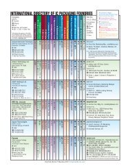
IC Assembly and Test Market Poisedfor Growth in <strong>2010</strong>The market and the Top 10 (11) players are analyzedBy Ron Molnar [AZ Tech Direct, LLC]After dismal 2008 and 2009performances, the semiconductormarket and its subset, ICassembly and test, are poised for substantialgrowth in <strong>2010</strong>. Bill McClean, President ofIC Insights, a leading market research firm,reported at the recent Global BusinessCouncil meeting in Scottsdale, AZ, that theworldwide IC market is expected to grow27% in <strong>2010</strong> to $303 billion. The worldwide<strong>2010</strong> semiconductor market revenues areexpected to eclipse the previous highachieved in 2007.Semiconductor packaging has become amajor differentiator of semiconductorproducts and a major factor in productperformance. For some high performanceapplications, packaging, assembly, and test(PAT) now represents a significant portionof the IC product cost. For many hand-heldconsumer applications, advanced packagingin the form of chip-scale, leadless DFN orQFN plastic packages, and wafer-levelpackaging (WLP) enable the miniaturizationdemanded by consumers. To minimize capitalexpenditures and unit costs, and to achievevital time-to-market product introductions,integrated device manufacturers (IDMs) areoutsourcing more and more of their PATmanufacturing processes to semiconductorassembly and test services (SATS)companies around the world.Fabless semiconductor companies haveembraced the outsourcing model since themid-1980s and now form a solid base ofcustomers for the SATS industry. Over thelast decade, they have grown their revenues5-10x faster than IDMs and have capturednearly 25% of the global semiconductormarket. Based on their 2009 revenues, thelargest fabless IC companies are Qualcomm,AMD, Broadcom, MediaTek, Nvidia,Marvell, Xilinx, LSI Logic, and Altera. Eachof them contract with one or more SATScompanies for their IC packaging, assembly,and test needs.2009Rank123456789102008Rank Company HeadquartersCountry12345671189ASEAmkor TechnologySPILSTATS <strong>Chip</strong>PACPowertech TechnologyUTAC<strong>Chip</strong>MOS TechnologiesJCETKing Yuan ElectronicsUnisemTotal Top 10OthersTotal MarketTaiwanUnited StatesTaiwanSingaporeTaiwanSingaporeTaiwanChinaTaiwanMalaysia2008Revenue($M)2,9522,6581,9181,65899471151934941337312,5457,55620.1012009Revenue($M)2,5972,1791,7221,32698260036834231930010,7356,45217,187Table 1. Top 10 SATS Companies’ Revenues, 2009. (Source: Gartner, February <strong>2010</strong>)SATS MarketIn <strong>April</strong> 2008 <strong>Chip</strong> <strong>Scale</strong> <strong>Review</strong>reported, “The outsourced assemblyand test industry boasted two of itsbest years in 2006 and 2007, with severalkey players setting new records forincome and revenue.” However, thisdidn’t last long, and the SATS industrysuffered negative growth in both 2008and 2009. Devastating quarterlydeclines were reported from the end of2008 through early 2009. The U.S. stockmarket rebounded relatively sharplyfrom its <strong>March</strong> 2009 lows due in largepart to the unprecedented governmentactions and subsidies. Early forecastspredicted the SATS market woulddecline by as much as 30% in 2009, butit rebounded with the upturn in theeconomy.The total SATS industry revenue of$17.2 billion in 2009 actually declined only14.5% from the $20.1 billion in 2008 -considerably less than predicted. TheSATS industry continues to rebound. JimWalker, Research VP, SemiconductorManufacturing, of Gartner/Dataqueststates, “For <strong>2010</strong>, the SATS industry will2009Growth(%)-12.0-18.0-10.2-20.0-1.2-15.6-29.1-2.0-22.8-19.6-14.4-14.6-14.5experience growth of over 26% to $21.6billion, with a 5-year CAGR of 12.2%.”He goes on to say, “Going forward, theSATS market should account for morethan 50% of the IC assembly and testmarket by 2012.” That’s a major milestonefor the SATS industry.SATS RankingThe top ten SATS companiesaccounted for approximately 62.5% of thetotal global SATS market revenue in 2009.The largest seven SATS companies of theTop 10 in the world retained theirpositions from 2008 to 2009 as reportedby Gartner/Dataquest in their recent<strong>March</strong> 1, <strong>2010</strong>, Market Share Alert:Preliminary SATS Market Share,Worldwide, 2009 report (Table 1).Rounding out the last 3 positionsof the Top 10 for 2009 are JiangsuChangjiang Electronics Technology(JCET), King Yuan Electronics(KYEC), and Unisem. At No. 8, JCETis the first China-based company toachieve a Top 10 ranking. Carsemdropped from the Top 10 list in 2009one spot to No. 11.<strong>Chip</strong> <strong>Scale</strong> <strong>Review</strong>. <strong>March</strong>/<strong>April</strong> <strong>2010</strong> . [<strong>Chip</strong><strong>Scale</strong><strong>Review</strong>.com] 13
Billion Dollar ClubIndustry giants ASE and Amkorcontinued their strong grasp on the toptwo positions in the ranking andremained the only two SATS providerswith annual revenues eclipsing the $2billion threshold.In 2009, Advanced SemiconductorEngineering (ASE) of Taiwan againranked first. “Like our industry peers,ASE did not go through 2009 unscathed.However, with a good cost structure inplace we were able to manage a smallgrowth on the net earnings, and recordedoverall sales revenues of $2.6 billion,maintaining our industry leadershipposition,” said Rich Rice, ASE’s Sr. VicePresident, Sales, North America. Headded, “In the past few years, ASE hasmade substantial progress in copper wirebond. Today, with gold prices fluctuatingover $1,000 per ounce, copper is a hugecost advantage when considering goldis the single largest cost factor in mostwire bond package types. Throughdedicated investment we now have over1,500 copper wire bonders installed inmultiple factories serving over 50customers in volume production.”Figure 1. Copper wire bond line at ASE’sKaohsiung assembly facility (Source: ASE)In 2009, Amkor shipped nearly 7.7 billionpackages, which is over 5% of the world’stotal IC units sold. Amkor agreed to form anew assembly and test joint venture withNakaya Microdevices and Toshiba in Japanto be called J-Devices. Amkor also washonored in 2009 with Frost & Sullivan’sTechnology Innovation of the Year awardfor their line-up of new packagetechnologies: FusionQuad, through-moldvia (TMV), package-on-package (PoP), andflip-chip molded BGA.Siliconware Precision Industries Ltd.(SPIL), specializing in high-end ball gridarray packages and flip-chip solutions,maintained its No. 3 position in the SATSindustry. A breakdown by package typeof SPIL’s 4Q09 net revenues showed 45%from substrate-based packages, 28% fromleadframe-based packages, 17% frombumping and flip-chip BGA packages, 8%from testing, and 2% from other sources.Last month SPIL announced an agreementto sell its DRAM testers and LCD driverassembly and test operation lines to<strong>Chip</strong>MOS Technologies.In 2009, STATS <strong>Chip</strong>PAC finished againin the No. 4 position. Compared to SPIL,they derived 57.9% of their 2009 netrevenues from substrate-based packages,15.1% from leadframe-based packages,and 27.0% from test and other sources.Their top 10 customers in 2009 accountedfor 71.8% of net revenues. LastNovember, STATS <strong>Chip</strong>PAC announcedthat it had successfully demonstrated thereliability of its first generation, embeddedwafer-level ball grid array (eWLB)technology and ramped into high volumeproduction. The next generation is underdevelopment with its partners,STMicroelectronics and Infineon, forproduct offerings targeted to start in <strong>2010</strong>.Half Billion Dollar ClubSATS providers that focused heavilyon memory assembly and test did not fareso well in 2009, as witnessed by the 29.1%decline in <strong>Chip</strong>MOS Technologiesrevenues. Early evidence points to asurging DRAM market in <strong>2010</strong> whichshould lift <strong>Chip</strong>MOS revenues back overthe $500 million threshold. Oddly,Powertech Technologies (PTI) was thebest year-over-year performer in 2009 withonly a 1.2% decline in revenue. PTI’sproduction agreements with KingstonTechnology certainly helped prevent amajor decline like that felt by othersfocused on the memory segment. PTI,UTAC, and <strong>Chip</strong>MOS retained theirrespective 2008 rankings.United Test and Assembly Center(UTAC) Group, noted primarily for its testservices, retained its No. 6 position.UTAC Group recently expanded theirmanufacturing presence by acquiringASAT Ltd., adding a southern Chinafacility to complement their othermanufacturing sites in Singapore, Taiwan,and Thailand. This new acquisition hassince been renamed UTAC DongguanLtd. In 2004, only 6 years ago, ASAT Ltd.ranked as the 10th largest SATS companyin the world.Figure 2. UTAC Dongguan Ltd. manufacturingfacility (Source: UTAC Group)Rest of the Top 10JCET is the first China-based SATSprovider to advance into the Top 10ranking, settling in the No. 8 position for2009. Focused mainly on low leadcount,discrete assembly and test, JCET hasannual capacity of more than 25 billiondiscrete units, and 5 billion IC units. Thecompany was founded in 1972 and wentpublic in 2000.King Yuan Electronics Co., Ltd. (KYEC),founded in 1987, is one of the world’slargest providers of integrated circuit testdevelopment engineering, wafer probing,pre-assembly (wafer thinning and dicing),and final test. While offering no assemblyservices, KYEC held onto the No. 9position for 2009.Unisem (M) Sdn. Bhd., headquarteredin Malaysia, rounds out the Top 10 list in2009. Unisem extended its range of plasticpackage offerings in July 2009 when itentered into a cross-licensing agreementwith ASAT, Ltd. (now part of the UTACGroup). Included in the agreement wereUnisem’s etched leadless package (ELP),taped leadframe package (TLP) andASAT’s thin array plastic package(TAPP), and thermal leadless array (TLA)package.Figure 3. Carsem post-saw MLP package pickand-placeline (Source: Carsem)14<strong>Chip</strong> <strong>Scale</strong> <strong>Review</strong>. <strong>March</strong>/<strong>April</strong> <strong>2010</strong> . [<strong>Chip</strong><strong>Scale</strong><strong>Review</strong>.com]
Honorable MentionCarsem (M) Sdn. Bhd. slipped from theTop 10 list in 2009, but deserveshonorable mention. Carsem, like JCET,offers both assembly and test of a widerange of IC packages, but predominantlylower leadcount, plastic packages. InOctober 2009 they introduced anextremely thin micro leadframe package(MLP) having two leads and measuringonly 0.6 x 0.3 x 0.3 mm (similar in size to0201 surface mount components). Thistiny package was developed for thermalvoltage suppression diode applications.Packaging Foundry DirectoryThe <strong>2010</strong> directory of worldwide ICpackaging foundries, compiled this year byAZ Tech Direct, LLC, lists 61 companiesoffering IC assembly and test services. Itexpands from 38 listings in the 2009directory and includes 26 companiesheadquartered in the U.S. alone.Many of the U.S.-based companies aresmall and service their geographicregions of the country, offering quick turnassembly of prototypes andpreproduction volumes. Their ability toquickly assemble new IC designs in 1 to5 days for characterization and testing isinvaluable to IC designers. In general,they are capable of assembling cavitypackages, such as hermetic or epoxysealedceramic packages and/or liquidepoxy encapsulated (glob top) plasticpackages. Most provide wire bond and/or flip-chip assembly processes. Only afew of the larger SATS suppliers in theU.S. offer transfer molded encapsulationdue to the sizeable investment requiredfor presses, molds and trim/form die setsto cover the broad range of packagetypes. It comes as no surprise that moreand more domestic suppliers areplanning to establish molding capacityto offer the increasingly popularleadless DFN and QFN packages. Theserelatively new package types can beassembled on pre-plated, etchedleadframes, transfer molded in an array,singulated with dicing saws, and don’trequire dedicated trim/form tooling or alead finish plating line.The focus of this directory has been, andcontinues to be, on those SATS providersoffering primarily the assembly of discretediodes/transistors and integrated circuitsin single-chip, JEDEC-standard packages.As a result, companies offering primarilycontract test services, other than KYECwhich ranks as one of the Top 10 SATScompanies in the world, have beenexcluded. Also, those companies mainlyengaged in assembly of traditional hybrids,multichip modules, chip-on-board (COB)modules, system-in-package (SiP), MEMS/MOEMS, high power packages,optoelectronics including light emittingdiode (LED), packages and assemblies havealso been excluded from this directory.To update listings in the directory fornext year’s publication, please contact theauthor at surveys@aztechdirect.combefore January 31, 2011.<strong>Chip</strong> <strong>Scale</strong> <strong>Review</strong>. <strong>March</strong>/<strong>April</strong> <strong>2010</strong> . [<strong>Chip</strong><strong>Scale</strong><strong>Review</strong>.com] 15
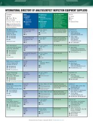
INTERNATIONAL DIRECTORY OF IC PACKAGING FOUNDRIESCOMPANYHEADQUARTERSCompanyStreet AddressCity, State, CountryTelephoneWebsiteMANUFACTURINGLOCATIONSCountry (Qty)CN = ChinaID = IndonesiaIN = IndiaIT = ItalyJP = JapanKR = KoreaMX = MexicoMY = MalaysiaPH = PhilippinesSG = SingaporeTH = ThailandTW = TaiwanUK = United KingdomUS = United StatesPACKAGETYPESCeramicCB = Ball ArrayCL = Leads/PinsCN = No LeadsPlastic (Molded)PB = Ball ArrayPL = Leads/PinsPN = No LeadsPlastic (No Mold)PC = Cavity/DamPF = Film/TapeOtherWL = Wafer LevelMC = Memory CardCONTRACTSERVICESSD = Substrate DesignBP = Wafer BumpingWP = Wafer ProbingWD = Wafer DicingWT = Wafer ThinningAS = AssemblyFT = Final TestET = Environmental TestBI = Burn-InASSEMBLYPROCESSESAD = Adhesive/GlassED = Eutectic/SolderWB = Wire BondFC = Flip <strong>Chip</strong>GT = Glob TopMP = Molded PlasticUF = UnderfillLP = Lead PlatingBA = Ball AttachLA = Lead AttachHS = Hermetic SealAdvanced Semiconductor Engineering, Inc.No. 26, Chin 3rd Rd., N.E.P.Z.Kaohsiung, Taiwan R.O.C.Tel: +886-7-361-7131www.aseglobal.comJP(1), KR (1)MY(1), SG(1)TW(2), US(1)PB, PL, PNSD, BP, WPWD, WTAS, FTFT, BIADWB, FCMP, UFLP, BAAdvotech Co., Inc.632 W. 24th StreetTempe, AZ 85282Tel: +1-480-821-5000www.advotech.comUS(1)CB, CL, CNPCSD, BPWD, ASFTAD, EDWB, FCGT, UFBA, HSAmkor Technology Inc.1900 S. Price RoadChandler, AZ 85286Tel: +1-480-821-5000www.amkor.comCN(2), JP(1)KR(3), PH(2)TW(3), SG(2)US(1)CB, CL, CNPB, PL, PNSD, BPWD, WTAS, FTETAD, EDWB, FCMP, UF, GTLP, BAHSAmTECH Microelectronics, Inc.6541 Via Del OroSan Jose, CA 95119Tel: +1-408-227-8885www.amtechmicro.comUS(1)CL, CNPL, PNSD, WDASETAD, EDWB, GTBA, HSAspen Technologies5050 List Drive, Suite CColorado Springs, CO 80919Tel: +1-719-592-9100www.aspentechnologies.netUS(1)CB, CL, CNPCSDBP, WDASAD, EDWB, FCGT, UFBA, HSAzimuth Industrial Co., Inc.30593 Union City Blvd., Suite 110Union City, CA 94587Tel: +1-510-441-6000www.azimuthsemi.comUS(1)CL, CNPL, PNWD, ASAD, EDWB, MPLP, HSCarsem (M) Sdn. Bhd.Jalan Lapangan Terbang, P.O. Box 20430720 Ipoh, Perak, MalaysiaTel: +60-5-312-3333www.carsem.comCN(1), MY(2)CB, CNPB, PL, PNSD, WPWD, WTAS, FTETAD, EDWB, FCMP, UFLP, BAHSCatalyst Microtech LLC5321 Industrial Oaks Blvd., Suite 105Austin, TX 78735Tel: +1-512-899-8422www.catalystmicrotech.comUS(1)CB, CL, CNPCWD, ASAD, EDWB, FCGT, UFBA, HS<strong>Chip</strong>bond Technology CorporationNo. 3, Li Hsin 5th Rd., Hsinchu Science Park,Hsinchu 300, Taiwan, R.O.C.Tel: +886-3-567-8788www.chipbond.com.twTW(2)PFSDBP, WPWD, WTAS, FTETAD, FCGT, UF<strong>Chip</strong>MOS TaiwanNo. 1, R&D Rd. 1, Hsinchu Science Park,Hsinchu 300, Taiwan, R.O.C.Tel: +886-3-577-0055www.chipmos.comCN(1), TW(2)PB, PL, PNPFSD, BPWD, WTAS, ETAD, WBFC, UFGT, MPLP, BA<strong>Chip</strong> Supply, Inc.7725 N. Orange Blossom TrailOrlando, FL 32810Tel: +1-407-298-7100www.chipsupply.comUS(1)CB, CL, CNPB, PN, PC, PFWLSDBP, WPWD, WTAS, FTET, BIAD, EDWB, FCGT, UFMP, BAHSCircuit Electronic Industries Public Co., Ltd.45 Moo 12 Rojana Industrial ParkAyutthaya, Thailand 13210Tel: +66-35-226-280www.cei.co.thTH(1)PL, PNPFSDWD, WTAS, FTETADWBMPLP16<strong>Chip</strong> <strong>Scale</strong> <strong>Review</strong>. <strong>March</strong>/<strong>April</strong> <strong>2010</strong> . [<strong>Chip</strong><strong>Scale</strong><strong>Review</strong>.com]
INTERNATIONAL DIRECTORY OF IC PACKAGING FOUNDRIESCOMPANYHEADQUARTERSCompanyStreet AddressCity, State, CountryTelephoneWebsiteMANUFACTURINGLOCATIONSCountry (Qty)CN = ChinaID = IndonesiaIN = IndiaIT = ItalyJP = JapanKR = KoreaMX = MexicoMY = MalaysiaPH = PhilippinesSG = SingaporeTH = ThailandTW = TaiwanUK = United KingdomUS = United StatesPACKAGETYPESCeramicCB = Ball ArrayCL = Leads/PinsCN = No LeadsPlastic (Molded)PB = Ball ArrayPL = Leads/PinsPN = No LeadsPlastic (No Mold)PC = Cavity/DamPF = Film/TapeOtherWL = Wafer LevelMC = Memory CardCONTRACTSERVICESSD = Substrate DesignBP = Wafer BumpingWP = Wafer ProbingWD = Wafer DicingWT = Wafer ThinningAS = AssemblyFT = Final TestET = Environmental TestBI = Burn-InASSEMBLYPROCESSESAD = Adhesive/GlassED = Eutectic/SolderWB = Wire BondFC = Flip <strong>Chip</strong>GT = Glob TopMP = Molded PlasticUF = UnderfillLP = Lead PlatingBA = Ball AttachLA = Lead AttachHS = Hermetic SealCirtek Electronics Corporation116 E. Main Ave., Phase V, SEZ,Laguna Technopark, BinanLaguna, PhilippinesTel: +63-49-541-2310www.cirtek-electronics.comPH(1)PL, PNSD, WPWD, WTAS, FTETAD, WBMP, LPHSColorado Microcircuits, Inc.6650 N. Harrison AvenueLoveland, CO 80538Tel: +1-970-663-4145www.coloradomicrocircuits.comUS(1)CB, CL, CNPN, PCSDWDASAD, EDWB, GTMP, HSCorwil Technology Corporation1635 McCarthy Blvd.Milpitas, CA 95035Tel: +1-408-321-6404www.corwil.comUS(1)CB, CL, CNPB, PL, PNPCSDBP, WPWD, WTAS, FTET, BIAD, EDWB, FCGT, UFMP, BAHSEEMS Italia Spa.Viale delle Scienze, 502015 Cittaducale Rieti, ItalyTel: +39-07-466-041 ?www.eems.comCN(1), IT(1)SG(1)PB, PL, PNSD, WPWD, WTAS, FTAD, WBMP, LPBAEndicott Interconnect Technologies, Inc.Building 258, 1093 Clark StreetEndicott, NY 13760Tel: +1-866-820-4820www.endicottinterconnect.comUS(1)PCSDWD ?, WT ?ASAD, WBFC, UFGT, BAEngent, Inc.3140 Northwoods Pkwy., Suite 300ANorcross, GA 30071Tel: +1-678-990-3320www.engentaat.comUS(1)PB, PNPCSD, BPWD, WTAS, FTETTAD, WBFC, UFGT, MPBAPFirst Level Inc.3109 Espresso WayYork, PA 17402Tel: +1-717-266-2450www.firstlevelinc.comUS(1)CL ?, CN ?PCSDBPWDASAD, EDWB, FCGT, UFBA, LAHSFormosa Advanced Technologies Co., Ltd.No. 329, Ho-Nan St., Touliu,640 Yunlin, Taiwan R.O.C.Tel: +886-5-557-4888www.fatc.com.twTW(1)PB, PLSD, WPWD, WTAS, FTBIAD, WBMP, LPBAGreatek Electronics, Inc.No. 136, Gung-Yi Rd., Chunan Cheng,Miaoli Hsien, Taiwan R.O.C.Tel: +886-37-638-568www.greatek.com.twTW(2)PL, PNSD, WPWD, WTAS, FTBIAD, WBMP, LPBAHANA Semiconductor (Ayutthaya) Co., Ltd.Hi-Tech Industrial Estate Authority of Thailand,100 Moo 1, T. Baan-Len, A. Bang Pa-In KM. 59Asia Road, Ayutthaya 13160, ThailandTel: +66-35-729-300www.hanagroup.comCN(1)TH(2)US(1)PL, PNPFSDWD, WTAS, FTETADWB, GTMP, LPHEI, Inc.1495 Steiger Lake LaneVictoria, MN 55386Tel: +1-952-443-2500www.heii.comUS(3)CNPBPNPFSDWDASAD, WBFT, UFMP, BAi2a Technologies3399 W. Warren AvenueFremont, CA 94538Tel: +1-510-770-0322www.ipac.comUS(1)PB, PL, PNPCASAD, EDWB, GTBA<strong>Chip</strong> <strong>Scale</strong> <strong>Review</strong>. <strong>March</strong>/<strong>April</strong> <strong>2010</strong> . [<strong>Chip</strong><strong>Scale</strong><strong>Review</strong>.com] 17
INTERNATIONAL DIRECTORY OF IC PACKAGING FOUNDRIESCOMPANYHEADQUARTERSCompanyStreet AddressCity, State, CountryTelephoneWebsiteMANUFACTURINGLOCATIONSCountry (Qty)CN = ChinaID = IndonesiaIN = IndiaIT = ItalyJP = JapanKR = KoreaMX = MexicoMY = MalaysiaPH = PhilippinesSG = SingaporeTH = ThailandTW = TaiwanUK = United KingdomUS = United StatesPACKAGETYPESCeramicCB = Ball ArrayCL = Leads/PinsCN = No LeadsPlastic (Molded)PB = Ball ArrayPL = Leads/PinsPN = No LeadsPlastic (No Mold)PC = Cavity/DamPF = Film/TapeOtherWL = Wafer LevelMC = Memory CardCONTRACTSERVICESSD = Substrate DesignBP = Wafer BumpingWP = Wafer ProbingWD = Wafer DicingWT = Wafer ThinningAS = AssemblyFT = Final TestET = Environmental TestBI = Burn-InASSEMBLYPROCESSESAD = Adhesive/GlassED = Eutectic/SolderWB = Wire BondFC = Flip <strong>Chip</strong>GT = Glob TopMP = Molded PlasticUF = UnderfillLP = Lead PlatingBA = Ball AttachLA = Lead AttachHS = Hermetic SealIDS Electronics Sdn. Bhd.IDS Park, Seri Iskandar,Bota, Perak, MalaysiaTel: +60-5-371-2288www.idsesb.com.myMY(1)PLPNWPWD, WTAS, FTETAD, WBMP, LPInfiniti Solutions Ltd.122, Middle Road, Midlink Plaza #04-01Singapore 188973Tel: +65-6336-0082www.infinitisolutions.comPH(1)US(1)CL, CNPL, PNSD, WPWD, WTAS, FTAD, ED, WBMP, LPHSInterconnect Systems, Inc.759 Flynn RoadCamarillo, CA 93012Tel: +1-805-482-2870www.isipkg.comUS(2)MX(1)PC, PFSDASAD, WBFC, UFGTJiangsu Changjiang Electronics Technology Co., Ltd.No. 275, Binjiang Rd., Middle Jiangyin,Jiangsu, ChinaTel: +86-0510-8685-6417www.cj-elec.comCN(3)PL, PNWD, WTAS, FTAD, WBMP, LPKingpak Technology Inc.No. 84, Tai-ho Rd., Chu-Pei 302,Hsin-chu Hsien, Taiwan R.O.C.Tel: +886-3-553-5888www.kingpak.com.twTW(1)CN(1)PB, PNMCSDWP, WD, WTAS, FTAD, WBGT, MPBAKing Yuan Electronics Co., Ltd.No. 81, Sec. 2, Gongdaowu RoadHsin-chu 300, TaiwanTel: +886-3-575-1888www.kyec.com.twTW(4)n/aWP, WD, WTFT, BIn/aKyocera America Inc.8611 Balboa AvenueSan Diego, CA 92123Tel: +1-858-576-2600http://americas.kyocera.com/kai/semipartsUS(1)CB, CL, CNPB, PLSDWD, WTAS, ETAD, EDWB, FCUF, GTLP, BAHSLingsen Precision Industries Ltd.5-1, Nan 2nd Road, T.E.P.Z.Taichung 42701 Taiwan R.O.C.Tel: +886-4-2533-5120www.lingsen.com.twTW(2)PB, PL, PNMCSD, WPWD, WTAS, FTETAD, WBMP, LPBAMajelac Technologies, Inc.262 Bodley RoadAston, PA 19014Tel: +1-610-459-8786www.majelac.comUS(1)CL, CNPB, PL, PNPCSDWDASADWB, FCGT, MP, UFBA, HSMaxtek Components Corporation2905 SW Hocken AvenueBeaverton, OR 97005Tel: +1-503-627-4521www.maxtek.comUS(3)CL, CNPBSDWP, WDAS, FTET, BIAD, EDWB, FCMP, UFBA, HSMillenium Microtech Group17/2 Moo 18, Suwintawong Rd.,Tambon SaladangBannumprielu, Chacherngsao 24000, ThailandTel: +66-38-845-530www.m-microtech.comTH(1)CN(1)CL, CNPLSD, WPWD, WTAS, FTET, BIAD, EDWB, MPLP, HSOptocap, Ltd.5 Bain SquareLivingston, Scotland, UK EH54 7DQTel: +44-1506-403-550www.optocap.comUK(1)CL, CNSD, WDAS, ETAD, EDWB, FCGT, UF, MPBA, HS18<strong>Chip</strong> <strong>Scale</strong> <strong>Review</strong>. <strong>March</strong>/<strong>April</strong> <strong>2010</strong> . [<strong>Chip</strong><strong>Scale</strong><strong>Review</strong>.com]
INTERNATIONAL DIRECTORY OF IC PACKAGING FOUNDRIESCOMPANYHEADQUARTERSCompanyStreet AddressCity, State, CountryTelephoneWebsiteMANUFACTURINGLOCATIONSCountry (Qty)CN = ChinaID = IndonesiaIN = IndiaIT = ItalyJP = JapanKR = KoreaMX = MexicoMY = MalaysiaPH = PhilippinesSG = SingaporeTH = ThailandTW = TaiwanUK = United KingdomUS = United StatesPACKAGETYPESCeramicCB = Ball ArrayCL = Leads/PinsCN = No LeadsPlastic (Molded)PB = Ball ArrayPL = Leads/PinsPN = No LeadsPlastic (No Mold)PC = Cavity/DamPF = Film/TapeOtherWL = Wafer LevelMC = Memory CardCONTRACTSERVICESSD = Substrate DesignBP = Wafer BumpingWP = Wafer ProbingWD = Wafer DicingWT = Wafer ThinningAS = AssemblyFT = Final TestET = Environmental TestBI = Burn-InASSEMBLYPROCESSESAD = Adhesive/GlassED = Eutectic/SolderWB = Wire BondFC = Flip <strong>Chip</strong>GT = Glob TopMP = Molded PlasticUF = UnderfillLP = Lead PlatingBA = Ball AttachLA = Lead AttachHS = Hermetic SealOrient Semiconductor ElectronicsNo. 9, Central 3rd Street, N.E.P.Z.,Kaohsiung 811 Taiwan R.O.C.Tel: +886-7-361-3131www.ose.com.twTW(1)PH(1)PBPL, PNSD, WPWD, WTAS, FTET, BIAD, WBFC, UFMP, LPPantronix Corporation2710 Lakeview CourtFremont, CA 94538Tel: +1-510-656-5898www.pantronix.comCN(1)PH(2)US(1)CL, CNPB, PL, PNPCSDWD, WTAS, FTETAD, EDWB, MPFC, UFLP, BAHSPowertech Technology Inc.No. 26, Datong Rd., Hsinchu Industrial Park,Hukou, Hsinchu 30352 Taiwan R.O.C.Tel: +886-3-598-0300www.pti.com.twCN(1)TW(3)PB, MCPL, PNSD, WPWD, WTAS, FTET, BIAD, WBMP, LPBAPromex Industries, Inc.3075 Oakmead Village DriveSanta Clara, CA 95051Tel: +1-408-496-0222www.promex-ind.comUS(1)CL, CNPL, PNPCSD, WDAS, ETAD, EDWB, MPFC, UFGT, HSPsi Technologies, Inc.Electronics Ave., FTI Special Economic Zone,Taguig Metro Manila, PhilippinesTel: +63-2-838-4966www.psitechnologies.comPH(2)CL, CNPL, PNSD, WDAS, FTETAD, EDWB, MPLP, HSQuik-Pak10987 Via FronteraSan Diego, CA 92127Tel: +1-858-674-4676www.icproto.comUS(1)CL, CNPB, PL, PNPC, PFWD, WTAS, ETAD, EDWB, GTFC, UFBASemi-Pac Inc.1206 #F Mt. View Alviso RoadSunnyvale, CA 94089Tel: +1-408-734-3832www.semipac.comUS(1)CL, CNPCWDASAD, WBGT, HSSignetics Corporation483-3 Buphung-ri, Thanhyun-myun,Paju-si Gyungki-do, Korea 413-840Tel: +82-31-940-7660www.signetics.comKR(2)CB, PBPL, PNSD, WPWD, WTAS, FTETAD, WBFC, UFMP, LPBASigurd Microelectronics CompanyNo. 436, Sec. 1, Pei-Shing Rd., Chu-TungHsin-chu, Taiwan R.O.C.Tel: +886-3-595-9213www.sigurd.com.twCN(1)TW(3)CNPL, PNSD, WPWD, WTAS, FTET, BIAD, WBMP, LPSilicon Turnkey Systems801 Buckeye CourtMilpitas, CA 95035Tel: +1-408-432-1790www.siliconturnkey.comUS(1)CL, CNPCWP, WDAS, FTET, BIAD, EDWB, FCGT, UFHSSiliconware Precision Industries Co., Ltd.No. 123, Sec. 3, Da Fong Rd., Tan tzu,Taichung 427, Taiwan R.O.C.Tel: +886-4-2534-1525www.spil.com.twCN(1)TW(3)CNPB, PL, PNPFWLSD, BPWPWD, WTAS, FTETADWB, FCMP, UFLP, BASolitron Devices, Inc.3301 Electronics WayWest Palm Beach, FL 33407Tel: +1-561-848-4311www.solitrondevices.comUS(1)CNPL, PNSD, WDAS, FTETAD, EDWB, MPHS<strong>Chip</strong> <strong>Scale</strong> <strong>Review</strong>. <strong>March</strong>/<strong>April</strong> <strong>2010</strong> . [<strong>Chip</strong><strong>Scale</strong><strong>Review</strong>.com] 19
INTERNATIONAL DIRECTORY OF IC PACKAGING FOUNDRIESCOMPANYHEADQUARTERSCompanyStreet AddressCity, State, CountryTelephoneWebsiteMANUFACTURINGLOCATIONSCountry (Qty)CN = ChinaID = IndonesiaIN = IndiaIT = ItalyJP = JapanKR = KoreaMX = MexicoMY = MalaysiaPH = PhilippinesSG = SingaporeTH = ThailandTW = TaiwanUK = United KingdomUS = United StatesPACKAGETYPESCeramicCB = Ball ArrayCL = Leads/PinsCN = No LeadsPlastic (Molded)PB = Ball ArrayPL = Leads/PinsPN = No LeadsPlastic (No Mold)PC = Cavity/DamPF = Film/TapeOtherWL = Wafer LevelMC = Memory CardCONTRACTSERVICESSD = Substrate DesignBP = Wafer BumpingWP = Wafer ProbingWD = Wafer DicingWT = Wafer ThinningAS = AssemblyFT = Final TestET = Environmental TestBI = Burn-InASSEMBLYPROCESSESAD = Adhesive/GlassED = Eutectic/SolderWB = Wire BondFC = Flip <strong>Chip</strong>GT = Glob TopMP = Molded PlasticUF = UnderfillLP = Lead PlatingBA = Ball AttachLA = Lead AttachHS = Hermetic SealSPEL Semiconductor Ltd.5 CMDA Industrial Estate,MM Nagar (Chennai) 603209, IndiaTel: +91-44-4740-5473www.spel.comIN(1)PL, PNSD, WPWD, WT ?AS, FTETAD, WBMP, LPStars Microelectronics (Thailand)Public Co., Ltd.605-606 Moo 2, EPZ,Bang Pa-In Industrial Estate,Klongjig, Bang Pa-In, Ayutthaya 13160,ThailandTel: +66-35-221-777www.starsmicroelectronics.comTH(2)PL, PNSD, WDAS, FTETAD, WBMP, LPSTATS-<strong>Chip</strong>PAC Ltd.10 Ang Mo Kio Street 65,#05-17/20 Technopoint,Singapore 569059Tel: +65-6824-7777www.statschippac.comCN(1), KR(1)MY(1), SG(1)TH(1), TW(1)US(2)PB, PL, PNWLSD, BPWP, FTWD, WTAS, ETAD, WBFC, UFMP, LPBATaiwan IC Packaging Corporation2, South 3 Road,Kaohsiung Export Processing ZoneKaohsiung, Taiwan R.O.C.Tel: +886-7-815-8800www.ticp.com.twTW(1)PL, PNMCSD, WDAS, FTAD, WBMP, LPTaiwan Micropaq CorporationNo. 4, Wenhua Rd., Hsinchu Science Park,Hu-kou, Taiwan R.O.C.Tel: +886-3-597-9402www.tmc.com.twTW(3)PB, PL, PNMCSD, WPWD, WTAS, FTETAD, WBMP, LPBATeam Pacific CorporationElectronics Ave., FTI ComplexTaguig City 1630, PhilippinesTel: +63-2-838-5005www.teamglac.comPH(1)CNPLSDWDAS, FTETAD, WBMP, LPHSTong Hsing Electronic Industries, Ltd.55, Lane 365, Yingtao Road, Yinko,Taipei Hsien, Taiwan R.O.C.Tel: +886-2-2679-0122www.theil.comPH(1)TW(1)CNPBSD, WPWD, WTAS, FTETAD, EDWB, MPFC, UFBA, HSUnisem (M) Berhad9th Floor, UBN Tower, No. 10 Jalan P. Ramlee,50250 Kuala Lumpur, MalaysiaTel: +60-3-2072-3760www.unisemgroup.comCN(1), ID(1)MY(1), UK(1)US(1)PB, PL, PNWLSD, BPWP, WD, WTAS, FTET, BIAD, WBFC, UFMP, LPBAUnited Test & Assembly Center Ltd.5 Serangoon North Ave 5Singapore 554916Tel: +65-6481-0033www.utacgroup.comCN(3), SG(2)TH(1), TW(1)PB, PL, PNWL, MCSD, WPWD, WTAS, FTET, BIAD, WBFC, UFMP, GTLP, BAVigilant Technology Co., Ltd.Ladkrabang Industrial Estate,Export Processing Zone 3,322 Moo 4 Chalongkrung Rd.,Laplatiew, Ladkrabang,Bangkok 10520, ThailandTel: +66-2-739-6203www.vigilant-techno.comTH(1)PLSDWD, ASFT, ETAD, WBMP, LPVLSIP Technologies Inc.750 Presidential DriveRichardson, TX 75081Tel: +1-972-437-5506www.vlsip.comUS(1)PB, PL, PNPCSD, WDAS, FTETAD, EDWB, FCGT, UF, MPBA, HSWalton Advanced Engineering, Inc.No. 18, North First Road, K. E. P. Z.Kaohsiung 806, Taiwan R.O.C.Tel: +886-7-811-1330www.walton.com.twCN(1)JP(1)TW(1)PB, PLSD, WPWD, WTAS, FTET, BIAD, WBMP, LPBA20<strong>Chip</strong> <strong>Scale</strong> <strong>Review</strong>. <strong>March</strong>/<strong>April</strong> <strong>2010</strong> . [<strong>Chip</strong><strong>Scale</strong><strong>Review</strong>.com]
EconomicOutlook <strong>2010</strong>By Sandra Winkler, Contributing Editor[slwinkler@newventureresearch.com]According to the Chinese calendar <strong>2010</strong> is a tiger year, and certainly,by comparison to 2009, the year will roar ahead. IC revenueis expected to grow at 18.8% and unit growth at 18% in<strong>2010</strong>, considerably better than the 8.8% decline in revenue and6.9% decline in units in 2009.What’s Hot in ICsDRAMs are anticipated to be the largest growth area for ICs with40% revenue growth in <strong>2010</strong>. Numerous analog chips includingregulators and references, computer, communications, automotive, andindustrial applications; special purpose logic chips including consumer,computer, communications, and automotive; flash, EEPROM, 32-bitMCU, standard cell, and PLD chips will all see revenue growth rates inexcess of 15%.Why the Upturn?Low interest rates, low oil prices, and the stimulus packages thatwere instituted around the world are all contributing to a stabilizingeconomy and upturn. Purchases were less than the replacement marketin 2009, and pent up demand is pulling the market in a positive direction.Cell phones, particularly the high-end smartphones, will see highgrowth rates. Smartphones are gaining in popularity and are becominga larger piece of the cell phone pie. Anything handheld and somewhataffordable that keeps us connected to the rest of the world seems to bedoing well. New product introductions such as Apple’s iPhone andiPad are becoming hot topics, and the Blackberry by Research in Motion(RIM) has been doing well for some time.Netbook computers, with prices as low as $200 during holiday sales,and notebook computers are quite popular. Other high growth areasinclude 3D and digital TVs, DSL/cable modems, flash drives, memorycards, set top boxes, digital cameras, automotive, and an assortment ofaudio applications.The economy is stabilizing, which is easing fears of spending onconsumer goods. The housing market, which took down theeconomy by taking the credit markets down with it, is stabilizing,and the ratio of income to housing expenditure is more balancedthan it was previously. The automotive market, which is host fornumerous ICs, had fallen substantially during the downturn. Thismarket did benefit from the cash-for-clunkers program and, althoughautomotive sales fell back after the program ended, it became abooster to spending. Automotive is expected to turn up in <strong>2010</strong> andbeyond, particularly in places such as China. Overall, spending ishigher now than it was in the depths of 2009. And that is what ispulling this year of the tiger up and out of the sloth of 2009, and willcarry us to a more positive future.<strong>Chip</strong> <strong>Scale</strong> <strong>Review</strong>. <strong>March</strong>/<strong>April</strong> <strong>2010</strong> . [<strong>Chip</strong><strong>Scale</strong><strong>Review</strong>.com] 21
State-of-the-art and Trends in 3D IntegrationMaking good progress, but major challenges still lie aheadBy John H. Lau [Industrial Technology Research Institute, Taiwan, ROC]3D integration consists of 3D IC and Figure 2) by stacking memory chipspackaging, 3D IC integration, and with wire bonds and die attachments.3D Si integration. They are different Today, 28-chip memory stacking is notand in general the TSV (through-silicon via) uncommon. Package-on-package (PoP),separates 3D IC packaging from 3D IC such as a flip-chip with solder bumpsintegration and 3D Si integration since the attached to a substrate which is supportinglatter two use TSV but 3D IC packaging two stacked chips with wire bonds, isdoes not. TSV for 3D integration is a morethan-26-year-oldtechnology. Even the and PoP are mature technologies in highshown in Figure 2. 3D memory stackingcoplanar GaAs RF MMIC (monolithic volume production (Figure 1 and FigureFigure 3. Moore’s law versus more-than-Mooremicrowave integrated circuit) used via hole 2) 1,2 and will not be discussed.grounding technology in 1975 (35 years(when there are volumes) the packagingago), but it was not for 3D integration. In 3D IC Integration Technology assembly and test houses will do it all.this investigation, TSV (with a new concept As shown in Figure 3, while they are The Holy Grail of 3D IC integrationthat every chip could have two active different, both 3D IC integration and 3D Si (heterogeneous integration) is shown insurfaces) is the focus. State-of-the-art, key integration are more-than-Moore Figure 3, where some of the chips, for example,differences, trends of these three technologies.microdisplay, microelectromechanicaltechnologies, and a 3D integration roadmap FEOL (Front End of Line) is usually systems (MEMS), opto, memory,are presented.performed in semiconductor fabrication microprocessor, optoelectronic, multipleplants (commonly called fabs) to pattern output dc-dc converter, application specific3D IC Packaging Technology active devices such as transistors. The IC (ASIC), microcontroller unit (MCU), digital3D IC packaging consists of two or more process is from a bare wafer to passivation, signal processor (DSP), microbattery, andconventional components (packages) which covers everything except the analog-to-digital (A/D) mixed signal arestacked in the vertical direction. The most bonding pads for the next level of combined and stacked in three dimensions.common is 3D memory stacking (Figure 1 interconnects.Two examples are shown in Figure 2. EightBEOL (Back End of Line) is usually memory chips, each 50μm thick, are stackedperformed in packaging assembly and test with microbumps and TSVs. Thirty two chips,houses and it involves everything after each 20μm thick, are stacked in a chip frompassivation, for example, UBM (under Samsung. Usually the electricalbump metallurgy), wire bonding, performance of 3D IC integration is bettermetallization, wafer bumping, backgrinding, than that of 2D SoC (system-on-chip) asdicing, assembly, and testing right before shown in Figure 3. However, there are majorPCB assembly.challenges in this quest.MEOL (Mid-End of Line) is performed Just as with many other newby combining some of the FEOL and BEOL technologies, 3D IC integration still facesFigure 1. 3D Integration Technologies versus technologies into a 3D IC integration many critical issues 1,2 :Maturity●technology which involves, for example, Known good dice (KGDs) are required.●TSV, microbumps, thin-wafer handling, Design guidelines and software aremetallization, UBM, wafer bumping, not available.●backgrinding, dicing, assembly, and testing. Test methods and equipment areThus, 3D IC integration must be executed lacking.●in the fabs and packaging assembly and TSV with redistribution layers (RDL)test houses. However, since the fabs’ are usually required.●equipment and personnel are too expensive Microbumps are usually required.●for making 3D IC integration and final test Wafer thinning and thin wafer handlingright before the printed circuit board (PCB) during processing are necessary.●assembly (which are not their core High equipment accuracy is necessaryFigure 2. 3D Integration Roadmap competence or major business), eventually for alignments.22 <strong>Chip</strong> <strong>Scale</strong> <strong>Review</strong>. <strong>March</strong>/<strong>April</strong> <strong>2010</strong> . [<strong>Chip</strong><strong>Scale</strong><strong>Review</strong>.com]
● Fast chips must be mixed with slowchips.● Large chips must be mixed withsmall chips.● 3D IC stacking inspection methodologyis needed.● 3D IC stacking expertise is lacking.● 3D IC stacking infrastructure is lacking.● 3D IC stacking standards are lacking.● Thermal issue - the heat flux generatedby stacked multifunctional chips inminiature packages is extremely high.● Thermal issue - 3D circuits increasetotal power generated per unit surfacearea.● Thermal issue - chips in a 3D stack mayoverheat if proper and adequatecooling is not provided.● Thermal issue - the space between the3D stack may be too small for coolingchannels (no gap for fluid flow).● Thermal issue - thin chips may createextreme conditions for on-chip hotspots.Key enabling technologies for 3D ICintegration are TSV w/o RDL, thin waferstrengthening and handling, microbumps,and thermal management. Design, test,reliability, and cost are always important butthey are out of the scope of this study.TSV w/o RDLThe most important key enablingtechnology for 3D IC integration is TSVw/o RDL. It provides advanced verticalinterconnects and system-in-package(SiP) solutions such as C2C (chip-tochip),C2W (chip-to-wafer), and W2W(wafer-to-wafer) stacking; wafer-levelpackaging and redistribution; interposerpackaging; and the shortest electricalpath (vertical-electrical feed-through) andlowest signal loss between two sides ofa silicon interposer (either passive oractive).Figure 4. With TSV, every chip could have twoactive sidesUnlike 3D IC packaging which put, forexample, wire bonds, solder bumps, goldstud bumps or anisotropic conductiveadhesives on the bonding pads of thepassivation wafer made by the FEOL, thefirst thing which the 3D IC integration(MEOL) does is to “dig” holes (TSVs)through the passivation and between thedevices/circuits of the wafer. This is novel,which opens up the doors for many newand useful applications. For example, amemory can use a CPU as its activeinterposer (Figure 4). A MEMS device canbe integrated with an ASIC chip 1 and LEDdevices can be mounted on an active chip 1 ,all of which can be assembled into a 3Dstructure. All of these are in the 3D ICintegration roadmap (Figure 2) and theiradvantages are better performance, smallerform factor, less footprint, lighter weight,and potentially lower cost.It should be pointed out and emphasizedthat a few years ago, once the (active) frontsideof a chip was flipped on a substrate orPCB, there was nothing that could be doneon its backside except attaching a heatspreader/sink. With TSVs, there is nodistinction of front-side and backsideanymore, which implies that a chip can haveboth top and bottom sides with circuits(Figure 4). This opens the doors wide formany innovative applications.3D IC Packaging versus 3D ICIntegrationThe biggest difference between 3D ICintegration and 3D IC packaging is that 3D ICintegration utilizes the TSV to connect chipsin the vertical direction while the 3D packagingdoes not. The advantages of 3D IC integrationover 3D packaging are smaller footprint,smaller form factor, less weight, higherperformance, less power, and potentially lowercost. These are key goals for system houses.Some of the challenges (opportunities) facing3D IC integration are high-yield TSV w/o RDLfabrication, thin chip/wafer strengthening/handling, microbumps, thermal management,inspection and testing, cost reduction, andreliability. Of course, design andcharacterization are always important.3D Si Integration Technology3D Si integration is one of the morethan-Mooretechnologies and is a veryold idea 3,4,5 . It consists of two or more<strong>Chip</strong> <strong>Scale</strong> <strong>Review</strong>. <strong>March</strong>/<strong>April</strong> <strong>2010</strong> . [<strong>Chip</strong><strong>Scale</strong><strong>Review</strong>.com] 23
layers of active electronic componentsintegrated vertically through TSV (it usedto be called vertical interconnection) intoa single circuit. It was trigged by theadvance of silicon-on-insulator (SOI)technology, first reported by Gat and hiscolleagues more than 30 years ago, whensemiconductor people thought Moore’slaw could be hitting the wall by the 1990s.Of course, the facts show that it did not.3D IC Integration versus 3D SiIntegrationThe biggest difference between 3D ICintegration and 3D Si integration is that thelatter does not use bumps (bumpless), suchas Cu, solder, or Au, or conductive adhesiveto bond/connect two wafers together(Figure 2 and Figure 3). There is no (orinfinitesimal) gap between wafers andthermal management can be a very bigproblem. In addition, W2W is the only wayto perform the bonding operation. Unlike3D IC integration, which utilizes C2C, C2W,or W2W bonding methods, the yield is abig issue (some bad chips are assembledon good chips). Furthermore, TSV size for3D Si integration is much smaller (~1μm andeventually sub-micron, see Figure 2) andthus the TSV manufacturing yields are lower.Finally, the bonding conditionrequirements for 3D Si integration such assurface cleanness, surface flatness, and theclass of clean room (which heavily affectsthe yield) are much tougher than those for3D IC integration (Table 1). There are twodifferent W2W bonding methods for 3D Siintegration, Cu-to-Cu 4 and oxide-to-oxide 5as shown in Figure 5 and Figure 6respectively.The advantages of 3D Si integration over3D IC integration are better electricalperformance, less power, lower profile, lessweight, and potentially lower cost. Thethermal management of 3D Si integration ismuch tougher than that of 3D IC integration.Semiconductor personnel have been trying3D Si integration for more than 25 yearsand there is no volume production in sightin the next 10.TSV Process FlowThere are many TSV processes, forexample, via first, via last, and via middle.The most likely manufacturing processused by the industry for making TSV w/oRDL for 3D IC integration is shown inFigure 7. There are five key steps tomaking the TSV:1.Via formation by either deep reactiveion etch (DRIE) or laser drilling2. SiO 2deposition by either thermaloxidation for passive interposers orPECVD (plasma enhanced chemicalvapor deposition)3. Barrier and seed layer deposition byphysical vapor deposition (PVD) orelectrografting (eG)4. Cu plating or W (tungsten) sputteringto fill the vias5.CMP (chemical and mechanicalpolishing) of Cu plating residues(overburden)For bare wafers and passiveinterposers, a SiO 2layer is needed beforethe photoresist. For active chips (forexample, ASICs and processors) andactive interposers, because of theirpassivation layer, only cleaning isneeded. Next, the front-side metallization/Figure 6. MIT’s W2W (SiO2-SiO2) bondingTable 1. Solder microbump bonding versusbumpless bondingFigure 5. IBM’s W2W (Cu-Cu) bonding24 <strong>Chip</strong> <strong>Scale</strong> <strong>Review</strong>. <strong>March</strong>/<strong>April</strong> <strong>2010</strong> . [<strong>Chip</strong><strong>Scale</strong><strong>Review</strong>.com]UBM is made on the blind TSV wafer,which is usually thicker than 300μm.In most 3D IC integration applications,the thickness of the passive/activeinterposers ranges from 100μm to 200μmand of the stacked memory chips, from 20μmto 50μm. Thus, most of the TSVs fabricatedare blind vias and a support wafer (carrier)is needed for the remaining processes.Once the carrier is temporarily bondedto the blind TSV wafer, it can be thinneddown to expose the TSV. Next are, forexample, backside metallization/UBM andwafer bumping. Then the carrier isdebonded from the TSV w/o RDL wafer.Finally, the TSV wafer is ready for eitherW2W bonding (recommended only forvery high chip yield wafers or one of themis not an active wafer, for example, thecap wafer for MEMS or the lens wafer forLED applications) or diced into individualchips for C2C or C2W bonding.The TSV size should be as small aspossible (< 30μm) because of less thermalexpansion mismatch between the Si (thermalexpansion coefficient (TEC) = 2.5x10 -6 / o C)and Cu (TEC = 18.5x10 -6 / o C) 1 , less Cuplating, higher throughput, and more spacefor routing. 5μm to 10μm vias for 3D ICintegration are not uncommon.As of today, the only 3D IC integrationvolume product (CMOS image sensor withTSV) is not using expensive“semiconductor” equipment such as theDRIE, PECVD, PVD, or CMP, but low-costPCB technology tools 6. Beside CMOSimage sensors, due to their simplicity, 3DMEMS 1 and 3D LED 1 are the most likelycandidates for applying low-cost 3D ICintegration technology. However, for highperformancememory stacking and passive/active interposers, the PCB technology maynot be able to handle the large number, smallsize, and/or fine pitch of vias, and theFigure 7. The most likely TSV manufacturingprocess
expensive “semiconductor” equipment isneeded.Critical Issues for TSVAs with many other new technologies,TSVs still face many critical issues. In thedevelopment of TSVs, the following mustbe noted and understood 1,2 :● Today, the only TSV 3D IC volumeproduct is the CMOS image sensormade by the most simple PCBprocess 6● TSV cost is higher than that of wirebonding● TSV design software is lacking● TSV design guidelines are notcommonly available.● Copper filling helps on thermalproblems but increases TCE (thermalcoefficient of expansion)● Void-free copper filling usually takesa long time (lower throughput)● The TSV cost for poor-yield IC wafersis high because many TSVs arewasted on the bad dice● There is a high cost for low TSV wafermanufacturing yield, especially forhigh-cost dice● TSV wafer yields are high (>99.99%)● Single-point touch-up on the TSVwafer is difficult● TSVs with high aspect ratios aredifficult to manufacture at high yield● TSV wafer warpage is a problemowing to the TCE mismatch betweensilicon and copper● Thin TSV wafer handling is necessaryduring all the processes● Test methodology and software forTSV are lacking● High-volume production tools arelacking and/or expensive● TSV inspection methodology andsoftware are lacking● TSV expertise, infrastructure, andstandards are lacking● What are the cost-effective andreliable TSVs and for what ICdevices?● How large is the TSV market?● What is the life cycle of TSV?Figure 8 and Figure 9 show a highperformance chip which (cannot besupported by an organic bismaleimidetriazene (BT)-substrate) is supported by apassive TSV interposer (Si-substrate) withtwo redistribution layers on top and one atthe bottom 7,8 . A very simple BT-substrateis used to fan out all the I/Os, power, andground to the PCB. The advance ofsemiconductor technology (because ofMoore’s law) is many times faster than thatof PCB, BT, and polyimide technologies,thus silicon is used as the substrate toreduce the cap. Figure 9 shows the TSVwith RDL wafer and the chip with its crosssections clearly showing the RDLs of theinterposer 7,8 . Figure 8 (top) shows a 3D X-ray with computed tomographics (CT)reconstruction of the Cu-filled TSVs withseams/voids. After process improvements,Figure 8 (bottom) shows a 3D X-ray withCT reconstruction of the Cu-filled, voidfreeTSVs. Thus, 3D X-ray is a powerfultool for nondestructive inspection of TSV.Figure 10 shows a very high-performanceSi memory chip attached to amicroprocessor chip (active Si interposer)with 2400 TSVs on a 25μm pitch and theaspect ratio (thickness/via-diameter) AR= 200/15 = 13.3 9 .In order to improve the TSVmanufacturing yield and enhance the TSVquality, the requirements, tasks, andmethods for each step are given inreference 1, where the hidden costs for3D IC integration are also provided anddiscussed.Figure 8. 3D X-ray with CT reconstruction forCu-filled TSVsFigure 9. Cross sections of the TSV Si interposer<strong>Chip</strong> <strong>Scale</strong> <strong>Review</strong>. <strong>March</strong>/<strong>April</strong> <strong>2010</strong> . [<strong>Chip</strong><strong>Scale</strong><strong>Review</strong>.com] 25
Figure 10. Cross section showing the highaspect ratio (13.3/1) TSVThin Wafer HandlingTo have high performance, low profile,and lightweight products with 3D ICintegration technology, the thickness of thechips/wafers is usually very thin. Making awafer thin is not a big problem. Most of theback-grinding machines can do the job andgrind the wafers to as thin as 5μm. However,handling thin wafers through all thesemiconductor fabrication and packagingassembly processes is difficult. Usually, thethin wafer is temporarily bonded on asupport wafer. Then it goes through all thesemiconductor fabrication processes suchas metallization, passivation and UBM, andthe packaging processes such asbackgrinding and solder bumping. After allthese, removing the thin wafer from thesupport wafer poses another big challenge.Two equipment groups are available forthin-wafer handling today, namely,3M+SUSS and EVG+Brewer Science.Figure 11 shows a very simple and lowcostsupport-wafer method for thin-wafer(50μm) handling. In order to reduce theresidual stress and remain crack-free duringde-bonding, one must reduce the pitch ofthe release holes (1mm in diameter) on theperforated wafer to 2mm and increase thenumber of perforations on the edge of theFigure 11. A low-cost, thin-wafer handlingmethodsupport wafer. These two optimizeddebonding methods allow more chemicalsolution to uniformly penetrate into thebonding adhesive and eventually debondthe wafer successfully 10 .Low-cost, Lead-free SolderMicrobumpsFor 3D IC integration, chips are verythin and thus conventional flip-chipsolder bumps (~100μm) cannot beused. Instead, very tiny bumps (
integration technology is far in thefuture. The electronics industry shouldstrive to make more high-volumeproducts with 3D IC integrationtechnology5. IC chip yield (Y T) plays the most importantrole in TSV manufacturing cost. If Y Tislow for a particular IC device, then it isnot cost effective to use the TSVtechnology (because it makes the gooddice too expensive), unless it iscompensated for by density,performance, weight, and form factor.6. TSV manufacturing yield (Y TSV) plays thesecond most important role in TSVmanufacturing cost. Since this is the firstpost-wafer processing after the ICsemiconductor fabs, the packagingassembly and test houses should striveto make Y TSV> 99.99%. Otherwise, it willmake the subsequent steps veryexpensive by wasting material andprocess on the damaged TSV dice.7. Wafer-bumping yield (Y B> 99.99%) playsthe third most important role in TSVmanufacturing cost. The waferbumping/packagingassembly and testhouses should strive to make Y TSVY B>99.98% to minimize the hidden cost,since they cannot afford to damage gooddice already having TSVs.8. Dates in the 3D IC integration roadmapmost likely will be postponed becauseof the tough requirements of TSVmanufacturing yield (YTSV > 99.99%)and the very high hidden costs 2 .9. Based on what happened about 20 yearsago to the low-cost, solder-bump, flipchip,and wafer-level packagingtechnologies, it will not be a surprise tosee that, at the early stage,semiconductor foundries would like todo TSV and wafer bumping, but whenthe volumes pick up, the packagingassembly and test houses will do it allbecause they are flexible. Also, their corecompetence and major business are tobuild packages for the chips from thewafers given (made and tested) by thesemiconductor foundries and to performthe final packaging test. Then they shiponly the good ones to EMS (electronicsmanufacturing services) who performthe PCB assembly, in-circuit test, system(also called final or functional) test, andship the product to the system houses’hubs for distribution. Some systemhouses prefer to have their EMS shipthem the in-circuit tested good PCBs,perform the final test in-house, and thenship the product. This is theinfrastructure and how the electronicsindustry works. Of course, for somespecial reasons or niche applications,there are always a few exceptions.AppendixThere are at least two different vias on achip. One is very tiny (< 0.1μm today) and theother is very large (> 5μm today). The tinyones are connected to devices such astransistors (4 tiny vias for each transistor) tobuild the first metal layer (Figure 15). Today,the number of these tiny vias, for many chips,already exceeds the world population of over7 billion. On the other hand, for the large viasthat we call TSV for 3D IC integration, thenumber is much less (< 100,000 today) andthe size is larger (a 5μm TSV is shown inFigure 15 to show their contrast). Foundriesare too expensive to make 3D IC integrationTSVs. This is also true for the via-middleapproach, which makes the TSVs before themetal layers.AcknowledgementThe author would like to thank Ian Yi-JenChan, PhD, of the Electronics &Optoelectronics Labs of ITRI for his strongsupport. He also would like to thank X.Zhang, PhD, and A. Yu, PhD, for their usefuldiscussions.References1. Lau, J. H., Reliability of RoHS Compliant2D & 3D Electronic Interconnects,McGraw-Hill, New York, NY, <strong>2010</strong>.2. Lau, J. H., “TSV Manufacturing Yieldand Hidden Costs for 3D IC Integration”,to be published in the IEEE Proceedingsof Electronic, Components &Technology Conference, Las Vegas, NV,June <strong>2010</strong>.3. Akasaka, Y., “Three-dimensional ICTrends”, Proceedings of the IEEE, Vol.74, No. 12, December 1986, pp. 1703-1714.4. Chen, K., S. Lee, P. Andry, C. Tsang, A.Topop, Y. Lin, Y., J. Lu, A. Young, M.,Ieong, and W. Haensch, W., “Structure,Design and Process Control for CuBonded Interconnects in 3D IntegratedCircuits”, IEEE Proceedings of<strong>Chip</strong> <strong>Scale</strong> <strong>Review</strong>. <strong>March</strong>/<strong>April</strong> <strong>2010</strong> . [<strong>Chip</strong><strong>Scale</strong><strong>Review</strong>.com] 27
Figure 15. Comparison of tiny vias with 3Dintegration TSVs28<strong>Chip</strong> <strong>Scale</strong> <strong>Review</strong>. <strong>March</strong>/<strong>April</strong> <strong>2010</strong> . [<strong>Chip</strong><strong>Scale</strong><strong>Review</strong>.com]International Electron Devices Meeting,(IEDM 2006), San Francisco, CA,December 11-13, 2006, pp. 367-370.5. Burns, J., Aull, B., Keast, C., Chen, C.,Chen, C. Keast, C., Knecht, J.,Suntharalingam, V., Warner, K., Wyatt, P.,and Yost, D., “A Wafer-<strong>Scale</strong> 3-D CircuitIntegration Technology”, IEEETransactions on Electron Devices, Vol. 53,No. 10, October 2006, pp. 2507-2516.6. Sekiguchi, M., Numata, H., Sato, N.,Shirakawa, T., Matsuo, M., Yoshikawa, H.,Yanagida, M., Nakayoshi, H., andTakahashi, K., “Novel Low Cost Integrationof Through <strong>Chip</strong> Interconnection andApplication to CMOS Image Sensor”, IEEEProceedings of Electronic Componentsand Technology Conference, San Diego,CA, May 2006, pp. 1367-1374.7. Zhang, X., T. Chai, J. H. Lau, C.Selvanayagam, K. Biswas, S. Liu, D.Pinjala, G. Tang, Y. Ong, S. Vempati, E.Wai, H. Li, B. Liao, N. Ranganathan, V.Kripesh, J. Sun, J. Doricko, and C. Vath,“Development of Through Silicon Via(TSV) Interposer Technology for LargeDie (21x21mm) Fine-pitch Cu/low-kFCBGA Package”, IEEE Proceedings ofElectronic, Components & TechnologyConference, San Diego, CA, May, 2009,pp. 305-312. (Also, accepted forpublication in IEEE Transactions inAdvanced Packaging.)8. Selvanayagam, C., J. H. Lau, X. Zhang,S. Seah, K. Vaidyanathan, and T. Chai,“Nonlinear Thermal Stress/StrainAnalysis of Copper Filled TSV (ThroughSilicon Via) and Their Flip-<strong>Chip</strong>Microbumps”, IEEE Transactions inAdvanced Packaging, Vol. 32, No. 4, Nov.2009, pp. 720-728.9. Yu, A., J. H. Lau, Ho, S., Kumar, A., Yin,H., Ching, J., Kripesh, V., Pinjala, D., Chen,S., Chan, C., Chao, C., Chiu, C., Huang, M.,and Chen, C., “Three dimensionalinterconnects with high aspect ratio TSVsand fine pitch solder microbumps.” IEEEProceedings of Electronic Componentsand Technology Conference, San Diego,CA, May 2009, pp. 350-354.10. Zhang, X., A. Kumar, Q. X. Zhang, Y.Y. Ong, S. W. Ho, C. H. Khong, V. Kripesh,J. H. Lau, D.-L. Kwong, V. Sundaram, RaoR. Tummula, Georg Meyer-Berg,“Application of Piezoresistive StressSensors in Ultra Thin Device Handlingand Characterization,” Journal of Sensors& Actuators: A. Physical, Vol. 156, Nov.2009, pp. 2-7.11. Yu, A., J. H. Lau, Ho, S., Kumar, A., Wai,Y., Yu, D., Jong, M., Kripesh, V., Pinjala, D.,Kwong, D., “Study of 15-¦Ìm-pitch soldermicrobumps for 3D IC integration.” IEEEProceedings of Electronic Componentsand Technology Conference, San Diego,CA, May 2009, pp. 6 -10.
Next-Gen Advanced Packages Spell Opportunity forBurn-in and Test CommunityBy Françoise von Trapp, Contributing Editor [3D InCites]Iwore a different hat at this year’sBiTS Workshop, held <strong>March</strong> 7-9,<strong>2010</strong>, in Mesa AZ. Yup - I set asidethe 3D crown and my trusty keyboardfor a day, put on the burn-in and test hatprovided by Fred Taber, CEO of BITSWorkshop, and stepped in front of thevideo camera to interview keynotespeakers and be the roving reporter onthe exhibition floor. Here’s a synopsisof some of those discussions.Benefits of adaptive testIn his keynote address, Ken Butler,Fellow at Texas Instruments,discussed the concept of adaptive test,comparing it to traditional testapproaches that involve applying afixed sequence to every device in thesame way. “When you move to anadaptive approach, you take intoaccount that processes vary, materialsvary, and likewise test must vary to dothe best possible thing for eachproduct,” said Butler. Rather than justperforming a one-off test to make rapiddecisions, adaptive allows for dataacquisition, movement, and analysis.While adaptive test doesn’t eliminatethe need for burn-in, it optimizes itsuse. In some cases it equals test timereduction, but more importantly itallows you to learn as much as possiblefrom each wafer in terms of processlearning, device debugging, andquality improvement.From a cost perspective, whileadaptive test may cost more as a unit,the benefit of increased yield drivesthe overall cost down. Butleremphasized the importance of lookingat packaging and test processesholistically, rather than at each unitcost, to get the big picture.Unfortunately, despite the obviousbenefits, the industry is slow to adoptadaptive test. Butler says this is partlydue to lack of infrastructure to supportit: better data bases, better datacommunication mechanisms. But thisalso turns into opportunity, he noted,citing several start-ups such as Optimaland Test Advantage that are workingon the EDA tools and software foradaptive test.Butler’s loudest message to themasses was the importance ofcollaboration. Gone are the days wheneveryone benefits by keepinginformation close to the vest. In theadaptive test world, sharing ofinformation is critical to everyone’ssuccess.Test in tray - If you don’t haveone, get oneTom Di Stefano, Centipede Systems,took the podium to talk about one areaof manufacturing where the back-endguys could take some tips from thefront-end guys to reduce cost and timeto test: handling. “Parts are becomingmore complex faster than we candevelop the tools to deal with them,”he remarked.His idea is to create a “lights-outautomation” process, similar to the oneused in wafer fabs, made easy by theexistence of the front opening unifiedpod (FOUP). However, the front-endhas the advantage of standard waferformats; all the varied packageconfigurations pose a challenge to theback-end. According to Di Stefano,this can be solved by reconstitutingpackaged dice into a rectangular arrayand creating a standard carrier thatappears the same to the automationtools. His company’s test-in-traytechnology enables full automationfrom the time the wafer is diced throughfinal assembly, packaging, and test. “Itprovides a vehicle for handling parts,”explained Di Stefano. “You can test apart before stacking and after in thesame type of tray.” This sounded tome like it could be adapted to testingdelicate 3D TSV stacks. “Absolutely,”said Di Stefano. In fact, he saysthey’ve been prototyping test-in-trayfor thin silicon for two years. Whilethis doesn’t solve the test issuesthemselves, it’s his opinion that itshould take care of the handlingportion.It’s ALWAYS about costBrandon Prior, Prismark Partners,focused his market update report on lowcost packaging and small form factorpackages, offering suggestions on howto reduce manufacturing andproduction costs on mostly mainstreampackages. He talked about whatpackages are being used in the industryand why, and what’s driving folks tolower cost solutions.Addressing the slow moving trend inthe industry, he said wire bond stillholds 80-85% of the market in terms ofunits. There’s been a migration awayfrom leadframe packages towards arraybased or substrate based approaches,and beyond that, flip chip packages,<strong>Chip</strong> <strong>Scale</strong> <strong>Review</strong>. <strong>March</strong>/<strong>April</strong> <strong>2010</strong> . [<strong>Chip</strong><strong>Scale</strong><strong>Review</strong>.com] 29
flip chip bare die, wafer level CSP, chipon-flex,and embedded die are allbecoming more important.Prior pointed out that, despite all thehype around 3D, it still represents lessthan 1% of all packaging value, and hedoesn’t expect it to reach 10-15% until2020. He reminded me that flip-chip took30 years to be considered main stream,and still when you talk to companiesworking in high volumes like Qualcommand ST Microelectronics, they say it’sstill more expensive and only used whenthe performance and form factorbenefits are required. “A newtechnology may be great and a lot ofpeople might use it, but it will take along time before it becomes a costcompetitive approach.”60 seconds of fameWe gave exhibitors 60 seconds of airtime to talk about the products theywere showcasing. It’s amazing whatthese guys could cram into thatamount of time. Here are a fewinteresting tidbits:● At the Multitest booth, BobChartrand explained the benefits ofthe company’s new flat pintechnology manufactured from aproprietary based metal resulting inpins that are three times harder andhave 10 times the feature sharpnessof regular pogo pins. This allowsthem to achieve Kelvin on finepitchwafer scale and BGApackages. Additionally, Multitesthas launched a burn-in groupdivision for high-powered burn-intesting.● Nick Langston of Yamaichi talkedabout the company’s conductive,super hard coating (CHS) that issaid to extend the life of springprobes or any electrical contact.Additionally, it reduces the amountof solder adhesion, therebylowering the cost of test.● R&D Circuits was showcasing itsembedded component technologywhich Tom Bresnan said had beengenerating lots of interest amongcustomers looking for better powerperformance right at the DUTboard.●Roger Weiss described hiscompany, Paricon Technologies, asa custom contact house that usesits core technology to manufacturecontactors for devices requiringtight control and finer pitches,while at the same time serving avariety of structures. The coretechnology is a high-performanceelastomer interconnection materialmade from very fine particles ofsilver plated nickel, blended withsilicone through an extrusionprocess. The resulting material isthen integrated into fixtures andstructures.● HCD was promoting its SuperButtonproprietary interconnect technologyfor higher electrical performance aswell as its SuperSpring interconnectfor enhanced mechanicalcompliance. Amit Varma, HCD’srepresentative, explained that there’sa trade-off between electrical andmechanical performance. “Whenyou’re working with high electricalcharacteristics, you’re going to haveto compromise on mechanicalperformance,” he noted.● Plastronics jumped on the 3Dwagon with booth signage thatrequired 3D glasses to read.According to Larry Furman, theywere looking for a fun way to gettheir customers to look at socketsin a different way. “We want themto look at the component groupsand decouple the design, ratherthan look at a fully integratedsocket,” he explained● Ila Pal of Ironwood Electronics gavea preview of the paper beingpresented at BiTS on adevelopment device to test a 3Dpackage-on-package (PoP) device.Pal explained that it’s not easy totest a development device in theback end, because it’s a two levelconnection. In the front end, youneed a four level connection to testthe same two packages. Onceeverything is good to go at thedevelopment stage, only a 2-leveltest will be needed in production.● Jim Johnson at Brush Wellman alsooffered a glimpse of the paper theywere presenting on a hightemperatureclad metal that can beused at temperatures above 200 o C.“It’s remarkable and hasn’t beendone before,” he noted.● Self-described inventor, Bill Sinclair,CEO of Aries Electronics, offered adetailed description of thecompany’s novel burn-in testsocket that works sideways ratherthan up and down. Sinclair says thisflexible design accommodates anassortment of device sizes, andincreases productivity for thesimple reason that you can get moreinto the burn-in oven at one time.To see the full videos of these interviews,logon to http://www.vbits.semineedle.com.Final ThoughtsIn challenge, there is alwaysopportunity. It’s clear that the burn-intest community continues to rise to theongoing challenges of increaseddensity, performance, and the formfactor needs that each generation ofadvanced packages dishes out, whilekeeping cost in mind.30<strong>Chip</strong> <strong>Scale</strong> <strong>Review</strong>. <strong>March</strong>/<strong>April</strong> <strong>2010</strong> . [<strong>Chip</strong><strong>Scale</strong><strong>Review</strong>.com]
High Temperature Stack-chip, Die-attach AdhesiveDevelopmentsCurrently solving many problems, but a new generation is needed.By Kevin Chung, Ph.D. [AI Technology, Inc.]The majority of die-attachapplications for chippackaging are done withsingulated dice and dispensed dieattachadhesive paste. Film adhesiveshave also been used for at least 10years for stack-chip applications.In recent years, the use of film dieattachadhesives in wafer-levelpackaging has been in high-volume usefor DRAM applications with greatsuccess. In this type of thin wafer-levelpackaging where the resulting devicesize and thickness are critical tocommercial success, die-attach film hasbeen steadily reduced to 10μm or lessin comparison to the 1-3mils bond linethickness for traditional die-attachsemiconductor packages.adhesives 2,3 , the use of epoxy filmadhesive with a coefficient of thermalexpansion (CTE) in the range of 40-60ppm/ o C, modulus of more than 10million PSI, and the bond-line thicknessof 10-20μm have produced parts ofadequate reliability for at least theDRAM packages.In this paper, we will examine thecriteria for wafer-level die attach withhigher efficiency, more reliability andhigher performance.We will also examine the effects ofinterconnection from chip to packageon the choice of die-attach solutions.The packaging, using wire bonding,flip-chip soldering, or the directmechanical contact attach from flip-chipto bond pads, effectively dictates thechoice of different wafer-level, dieattachsolutions.Figure 3a. Laminationof wafer onto dicing dieattachfilm (DDAF)Figure 3c. Shining UVto release diceFigure 3b. Dicingwafer with DDAFFigure 3d. Pickup dicefrom DDAFFigure 1. CPU is one of the great successes offlip-chip applicationDRAM is usually rectangular with atotal overall die-attach area smaller thanone square centimeter. This enables theuse of thin bond lines of less than 10μmwithout excessive internal stressinducedfailures even when the bond isreduced to much less than thecommonly acceptable bond lineof 1.5-3mils for reliable dieattachthickness 1 .While electronic packagesusing die-attach adhesive canachieve substantial relief of theinterfacial stresses with the useof thicker, low modulusWire bonding and flip-chipinterconnectionsWire-bonding is the predominant choicefor chip-to-package interconnections. Theproven efficiency and reliability result in acost effective solution for high volumeDRAM applications.Most of the stack-chip packaging forsmaller volume production uses pre-cut,die-attach film with great success andhigh reliability. These earlier stack-chipsolutions have been building DRAMwith 8 or more chips for many high-endapplications. These standard die-attachFigure 2. Stack-chip packages can be interconnected withwire bonding or special design inter-chip interconnection bridgesFigure 3e. Examining dice for packagingfilm adhesives tend to be a controlledthickness of 2-4mils. Figure 2 showstwo examples of these 3-D high densitypackages.As more chips are stacked on top ofeach other, wire-bonding interconnectionbecomes more difficult to execute. Manyingenious packaging schemes have beendeveloped by, for example, Vertical CircuitInc. 4 , on board flip-chip attach byShellcase, and through-silicon via (TSV)from Sharp, Fujitsu, and others 5 .In high volume commercial applications,the use of 10-20μm die-attach film adhesivehas proven to be reliable for this size and<strong>Chip</strong> <strong>Scale</strong> <strong>Review</strong>. <strong>March</strong>/<strong>April</strong> <strong>2010</strong> . [<strong>Chip</strong><strong>Scale</strong><strong>Review</strong>.com] 31
Figure 3. Dicing die-attach film processing ¨C die-attach film must becompatible with UV release layer and have the ability to flow and curerapidly, or flow with light pressure and cure without pressure, in order tomaintain productivityshape of chip for stacked chips from twoto three layers. With that number ofstacked chips, wire bonding can still bemanaged. The use of 10-20μm filmadhesive not only yields thinner devicesthat are attractive for cameras and othercommercial applications, but also providea more uniform and controlled flow of theadhesive and thus more reproducible wirebondinginterconnections.Standard wire-bonding chippackaging uses backside die attach thatcan use more traditional epoxy dieattachedfilm adhesives that areavailable from die-attach film adhesivemanufacturers from the USA 6,7 andJapan 8,9,10 . Figure 3 shows a prelaminatedwafer with 15μm die-attachfilm adhesive.Typical manufacturing process inusing wafer-level packaging is nowintegrated in terms of using dicing tapeand die-attach film that are directlylaminated on the wafer before dicing.The layering of such configurations isillustrated in Figure 2 and the processrepresented in Figure 3.for the largest wafertoday (12 inches).● DAF film adhesivemust be compatiblewith the use of UVrelease dicing tape torelease chip afterdicing operations.● Ability to allow stackchipbonding with highefficiency.● Ability to provide diebondingstability forwire-bonding operationof up to 250 o C for thehighest production ratepossible.● Most of the existing DDAF are meetingthe performance requirements ofJEDEC IPC level 3 or better for moisturesensitivity after packaging.● Depending on the bonding stabilityand moisture sensitive propertiesof DAF and the molding,encapsulation, or other electromechanicalprotection, the finisheddevices range from level 3 (in mostcases) to the best solutionsmeeting the level 1 requirement.● In case of high temperatureapplications beyond 150 o C, newernon-epoxy DAF can now withstandlong-term usage of 200 o C andbeyond.Die-bonding adhesive and stressrelief protectionTraditional flip-chip uses wirebonding and solder-bump reflow formost requirements. Higher speed,performance, and cost continue todrive semiconductor packagingtoward shorter path interconnectionsbetween each level of the stack-chippackages.The need to lower the cost ofpackaging has led to manyinnovative packaging solutions. Thelowest cost electronic devices suchas UHF RFID tags have beensuccessfully produced in largevolume using direct flip-chipmechanical compression contact 11 .However, they are limited to anoperational temperature of less than60 o C and they are not very stableagainst moisture.The fact that contact resistance canbe properly maintained for long-termusage within specified temperature andenvironmental constraints provideshope that solutions for highperformance applications can beachieved with more engineeredmaterials and packaging. Figure 5illustrates such flip-chip, direct contactinterconnection.The key for performance for this typeof package is the flip-chip underfill thatmust also perform as a stable diebondingadhesive. For the flip-chipunderfill adhesive to function properly,it must possess at least the followingcharacteristics:1. Underfill adhesive must be easilyplaced either on the substrate oron the interconnection front sideof the chip. Dicing die-attach film(DDAF) is still applicable. If pasteunderfill adhesive is to be useful,Adhesive properties and deviceperformanceThe material technology challengesthat enable the processes described inFigure 3 are many and have been metso far by dicing die-attach film (DDAF)adhesives from the USA and Japan.The following are some of thechallenges:● Very thin and stable film adhesive(typically epoxy-based) of 10-25μmFigure 4. Semi-conductor packaging from wafer DDAF to componentFigure 5. Flip-chip interconnection with direct mechanical contacts between precious metal bumps andpreservations on chip and package substrate respectively32<strong>Chip</strong> <strong>Scale</strong> <strong>Review</strong>. <strong>March</strong>/<strong>April</strong> <strong>2010</strong> . [<strong>Chip</strong><strong>Scale</strong><strong>Review</strong>.com]
Figure 6. Specialty fill-in adhesive and underfill adhesive with low CTE, highmodulus and high Tg is essential in the reliability of stack-chip packages usingthrough TSV technologyit must stay in place afterdispensing onto the substrate orchip.2. The underfill adhesive must notprevent contact when the chip andpackage substrate interconnectionsare lined up and compressed forbonding. Unlike the use of Z-axis,uniaxial, conductive adhesive, anyparticulate could be detrimental to theachievement of interconnections.3. High glass transition temperature andmodulus are required to maintain theelectrical contact and characteristics.For commercial and militaryapplications, it should be well above150 o C.4. The underfill adhesive should be as lowin coefficient of thermal expansion(CTE) as that of higher filled traditionalepoxy underfills (< 30 ppm/ o C).5. In order to provide reasonableproductivity, the underfill adhesivemust be capable of curing at 175-250 o Cin less than 10 seconds.6. To meet the JEDEC IPC Level 1 moisturesensitivity requirements, the moistureabsorption should be well below 0.5%in saturation.There are now non-epoxy based,high temperature, underfill adhesivesin paste or film format in thickness of25-75μm for such applications.TSV, specialty underfill, and viafilling for stress reliefTSV 12 stack-chip packagingrepresents the ultimate chipinterconnection performance for stackchippackages. The requirement forstress relief is evenmore critical tofilling in the vias ofthe TSV structureand between thestacking chips.For filling inthe TSVs, thespecialty fill-inadhesive requiresthe followingcharacteristics:● The fill-in adhesivemust have extremelow viscosity towick into the viaseasily with the capillary forces.● Once cured, they must have verylow coefficient of expansion (CTE)and preferably substantially below30ppm/ o C.● High glass transition temperature andmodulus are required to maintainthe electrical contact andcharacteristics. For commercial andmilitary applications, it should bewell above 150 o C.● Fill-in adhesive should cure in lessthan 10 seconds at 175-250 o C.There are now non-epoxy basedhigh temperature fill-in pasteadhesives that can easily fill in viasof 20μm for such applications. Figure 6depicts the TSV structure and thelamination between layers to providestress relief.ConclusionsFlip-chip electrical interconnectionbetween a chip bumped with goldstuds and its package substrate canbe done by direct compressioncontact with high reliability andmanufacturability. A new generationof flip-chip underfill adhesives areneeded with low moisture absorption,high Tg, low CTE, and high modulusto provide the stress relief thatenables even high I/O counts devicesto be packaged with high reliabilityand low moisture senstivity.Similar flip-chip underfilladhesive can also be very effectivefor fill in of through silicon vias andprovide stress relief betweenstacked chips.References1.IEEE TRANSACTIONS ONCOMPONENTS AND PACKAGINGTECHNOLOGIES, VOL. 29, NO. 4,DECEMBER 2006; Evaluation of DieStress in MEMS Packaging: Experimentaland Theoretical Approaches; Satyajit S.Walwadkar and Junghyun Cho; http://www.ws.binghamton.edu/~jcho/Files/PapersWalwadkar&Cho_IEEETrans.pdf2.E. Suhir, “Calculated ThermallyInduced Stresses in Adhesively Bondedand Soldered Assemblies”, Proc. of theInt. Symp. On Microelectronics, ISHM,1986, Atlanta, Georgia, Oct. 1986; http://hal.archives-ouvertes.fr/docs/00/18/94/58/PDF/therm05084.pdf3.K. Chung et al., “Tack-Free Flexible FilmAdhesives”, Hybrid Circuit Technology,May 1990; http://www.aitechnology.com/uploads/pdf/WHITE%20PAPER/interconnections.pdf4.Vertical Circuit Inc. http://verticalcircuits.com/news.php5.Dr. Kevin Gibb, “2008 - the year of thethrough silicon via (TSV)?” http://www.chipworks.com/blogs.aspx?id=4714&blogid=86 and Dr.Rajesh Krishnamurthy, <strong>Chip</strong>works; “Drillingand Filling, but not in your Dentist's Chair”,http://chipdesignmag.com/display.php?articleId=26416.AI Technology, Inc. http://www.aitechnology.com/products/dieattach/7.Henkel Electronics, www.henkelna.com8.FurukawaElelctric, http://www.furukawa.co.jp/english/what/2008/ene_080417.htm9.Hitachi Chemical, http://www.hitachi.com/GlobalSupport/ContactUs?form_type=global_support10.Lintec Corporation, http://www.lintec.co.jp/e-dept/english/adwill/products/di.html11.Alien Technology and RFID: Roll-torollprocessing of silicon-basedmicroelectronics http://usms.nist.gov/workshops/macroelectronics/05-Alien.pdf12.3D-TSVs spark packagingrevolution;http://www.eetasia.com/STATIC/ARTICLE_IMAGES/200809/EEOL_2008SEP01_TPA_MFG_NT_01_VSfig1.jpg<strong>Chip</strong> <strong>Scale</strong> <strong>Review</strong>. <strong>March</strong>/<strong>April</strong> <strong>2010</strong> . [<strong>Chip</strong><strong>Scale</strong><strong>Review</strong>.com] 33
34<strong>Chip</strong> <strong>Scale</strong> <strong>Review</strong>. <strong>March</strong>/<strong>April</strong> <strong>2010</strong> . [<strong>Chip</strong><strong>Scale</strong><strong>Review</strong>.com]
INTERNATIONAL DIRECTORY OF WAFER-BUMPING SERVICE PROVIDERSNotes: This list was compiled from data supplied by the respective providers and is not all-inclusive as to company or service offered. Advertisers in this issue are indicatedby boldface listings. CM=Consult Manufacturer.CompanyAddressCity, State, ZipCountryPhoneFaxFounding YearNumber of EmployeesMaximum Wafer Size (mm)Bump Pitches (µm)Bumping ServicesEquipmentA=Aligners, B=Stencil Printers, C=SteppersBumping TechnologiesJ=Jetting, P=Plating, BP=Ball/loading placement,S=Sputtered, SP=Stencil printing,CP=Copper pillar, O=OtherBump AlloysSAC=SnAgCu, Au=Gold, Eu=Eutectic,LF=Pb-free, HL=High lead, LA=Low alphaWebSiteContactAdditional OfficesAdvanpack Solutions Pte Ltd54 Serangoon North Ave 4Singapore 555854Tel: +65-6482-5995CMCM50 – 150Wafer Bumping and RDLand WLP CapabilitiesCMP, S, CP, 0Au, LF, HL, Cuwww.advanpack.comAmkor Technology Inc.1900 South Price Rd.Chandler, AZ 85286Tel: 480.821.5000Fax: 480.821.827619685,000+30060 to 300150-, 200- and 300mm waferbumping/test/die processingABP, P (electroplating), SEu, LF, HL, LAwww.amkor.comASE GroupKaohsiung, Taiwan 811Tel: +886.7.361.30941984CM300CMCMCMP, SPCMwww.aseglobal.comASE (U.S.) Inc.Santa Clara, CA 95054Tel: 408-986-6500<strong>Chip</strong>Bond Technology CorporationHsinchu Science ParkHsinchu, 300 TaiwanTel: 886-3-5678788CM300CMPrototype and High Volume WaferBump processing with other Assemblyand Testing Service capabilities availableCMP, S, SP, OLF, HL, Au, Pl+Auwww.chipbond.com.twEncinitas, CA 92023Tel: 949-285-6383<strong>Chip</strong>MOSHsinchu Science ParkHsinchu, TaiwanTel: 866-3-577-0055CM200CMGold Bumping ServicesA,CSAuwww.chipmos.com<strong>Chip</strong>MOS USASan Jose, CA 95134Tel: 408-922-2777Flip<strong>Chip</strong> InternationalDiv. of Rose Street Labs3701 E. University Dr.Phoenix, AZ 85034Tel: 602.431.60201996CM20070 (R&D), 150+ (production)Flip chip and wafer bumping, Ultra CSP,Elite CSP, copper pillars, thinning, plusbackend to tape & reel or chip traysA, CSputtered UBM, electrolessNi/Au UBM, SP, BP alloys, CPCMwww.flipchip.comi2a Technologies399 West Warren AveFremont, CA 94538Tel: 510.770.03221993 (formerly IPAC)CM200 (300 soon)50µm Au stud, 180µm solder bump,400+ WLPWL-CSP and flip chip ranges, bumpedwafers, finished package (WLP andFC), die in tape & reel or waffleBSPEu, LF, SnAgCuwww.i2a-tech.comIC Interconnect1025 Elkton DrColorado Springs, CO 80907Tel: 719.533.1030199812200 B 200µm+ENi/UBM combined with stencilprinted solder, low cost wafer bumpingCMSP, BPEu, HL, electroless UBM, SACwww.icinterconnect.com<strong>Chip</strong> <strong>Scale</strong> <strong>Review</strong>. <strong>March</strong>/<strong>April</strong> <strong>2010</strong> . [<strong>Chip</strong><strong>Scale</strong><strong>Review</strong>.com] 35
INTERNATIONAL DIRECTORY OF WAFER-BUMPING SERVICE PROVIDERSNotes: This list was compiled from data supplied by the respective providers and is not all-inclusive as to company or service offered. Advertisers in this issue are indicatedby boldface listings. CM=Consult Manufacturer.CompanyAddressCity, State, ZipCountryPhoneFaxFounding YearNumber of EmployeesMaximum Wafer Size (mm)Bump Pitches (µm)Bumping ServicesEquipmentA=Aligners, B=Stencil Printers, C=SteppersBumping TechnologiesJ=Jetting, P=Plating, BP=Ball/loading placement,S=Sputtered, SP=Stencil printing,CP=Copper pillar, O=OtherBump AlloysSAC=SnAgCu, Au=Gold, Eu=Eutectic,LF=Pb-free, HL=High lead, LA=Low alphaWebSiteContactAdditional OfficesInternational Micro Industries (IMI )1951 Old Cuthbert Rd. Bldg 404Cherry Hill, NJ 08034Tel: 856-616-0226Fax: 856-616-02261971 ( Founded )21300CMBumping and WLP utilizing electrodeposition process and specializing inhigh aspect ratio, fine pitch and pillarbump technologyAlignersP, S, CP, OSAC ( SnAgCu )Au, E, LF, HLwww.imi-corp.comMinami Co., Ltd.EMS Tsukuba Factory 38-325-Chome, Minami-Cho Fuchu-Shi,Tokyo 183-0026, JapanTel: +81.42.368.831119803030080µm (45µm diameter)Ball placement, reflow, washing, inspection,quick delivery, low cost, high qualityCMSP T P, SP, BPSolder paste and balls, SnAgCuwww.ho-minami.co.jpNEPES, Pte Ltd12 Ang Mo Kio Street 65Singapore 569060Tel: +65-6412-8181CM30050 – 150Turnkey solution for Bumping, Testingand Wafer Level PackagingCMP, S, CPLF, HL, Eu, Cuwww.nepes.com.sgPac Tech GmbHDivision of Nagase & Co., LtdAm Schlangenhorst 7-9 & 15-1714641 Nauen, GermanyTel: +49.3321.4495.100Fax:+49.3321.4495.110 .1995150300UBM 40µm, bump pitch solder 80µmWafer bumping for Ni/Au UBM, Ni/Pd/Auand thick Au for wire bonding; waferlevel solder bumping, BCB repassivation,wafer level redistribution, wafer thinning,wafer dicing, chip singulation, tape & reelASP T SP, BP, electroless UBM, JUBM: NiAu, NiPdAu; Solder:SnAgCu, SnPb, AuSnwww.pactech.dePac Tech USA Inc.,328 Martin Ave.,Santa Clara, CA 95050Tel: 408.588.1925Pac Tech Asia Sdn Bhd.,Bayan Lepas IndustrialZone, 11900 Bayan Lepas,Penang, MalaysiaSiliconware Precision Industries Co.Tantzu, Taichung, 427 TaiwanTel: +886.4.253415251984~14,800300180CMA, B, CP, SP, BP, sputtered UBMSn63/Pb37, Sn5/Pb95, SnAgCu,SnAg, SnCu, Au bumpwww.spil.com.twSiliconware USA Inc.,San Jose, CA 95110Tel: 888.215.8632STATS <strong>Chip</strong>PAC Ltd.Singapore 569059Tel: +65.6824.7777199414,873300CMPrinted, plated and ball drop bump,redistribution, flip chip interconnectand WLCSPA, B, CP, SP, BP, sputtered UBMEu, ultra low alpha HL, LFwww.statschippac.comSTATS <strong>Chip</strong>PAC Inc.,Fremont, CA 94538Tel: 510.979.8000All Companies listed have in-house wafer bumping capabilitiesListing does not include capability for Gold Wire Ball Bumping.The <strong>2010</strong> International Directory of Wafer Bumping Service Providers is compiled by AZ Tech Direct LLC.To update listings in the directory for next year’s publication, please contact the author at surveys@aztechdirect.com before January 31, 2011.36<strong>Chip</strong> <strong>Scale</strong> <strong>Review</strong>. <strong>March</strong>/<strong>April</strong> <strong>2010</strong> . [<strong>Chip</strong><strong>Scale</strong><strong>Review</strong>.com]
WHAT'S NEW!Nanoscale MEMS Made Inside aCMOS WaferA new technology to constructnanoscale MEMS within the structureof the actual CMOS wafer itself usingstandard, high volume CMOS lines, hasbeen announced by BoalabMicrosystems of Barcelona, Spain. Thetechnology uses the existing metallayers in a CMOS wafer to form theMEMS structure using standard masktechniques. “We have solved thechallenge of building MEMS in acompletely different way,” explainedDave Doyle, Baolab’s CEO.Baolab has successfully createdMEMS devices using standard 0.18μm,8” CMOS wafers with four or moremetal layers, and has achievedminimum feature sizes down to 200nanometres. The prototype stage hasalready proven the NanoEMStechnology and evaluation sampleswill be available later this year. Theseare aimed at handset designers andmanufacturers, and Power Amplifierand RF Front End Module markets.[www.baolab.com]Gantry Robots Get More CapacityDENSO, headquartered in Kariya,Japan, has announced that it hasincreased the payload capacity of itsXR-Series four-axis, compact gantryrobots from 3 kg to 5 kg. The new 5kgcapacity, which represents an increaseof over 60 percent, allows the robots tohandle a significantly wider range ofapplications. The XR-Series robotsfeature a ceiling mounted, SCARA robotcombined with a long-stroke Cartesianrobot. They can operate in manyapplications without the need of aconveyor.The robots havea reach of 200mm to300mm, an x-axisstroke of 850mm to1,660mm, a cycletime of 0.53seconds, andrepeatability of± 0.015mm. Typicalapplicationsinclude assembly, dispensing, materialhandling, and parts feeding. DENSORobotics offer robots, controllers andsoftware covering a wide range ofapplications. [www.densorobotics.com]Need a Class 100 Oven?The No. 836 is a 750 O F, electricallyheated,Class 100 cleanroom oven fromGrieve, Round Lake, IL, USA, and canbe used to bake various coatings ontoproducts at a customer’s facility.Workspace dimensions of this ovenmeasure 36” wide x 36” deep x 39” high.Incoloy sheathed tubular heatingelements provide 30KW of heating anda maximum temperature of 750 O F. A1000CFM, 1.5HP recirculating blowermaintains horizontal airflow across theload. The oven has 6” insulated walls,a 2B finish stainless steel interior, andan aluminized exterior.Additional equipment on this Grieveoven include a 30” x 24” x 6” thickstainless steel high temperature HEPArecirculating air filter, digitalprogramming temperature controller,manual reset excess temperaturecontroller with separate contactors,recirculating blower airflow safetyswitch, and a 10” diameter circular chartrecorder.[www.grievecorp.com]New Test Socket Claims 500,000InsertionsIronwood Electronics of Burnsville,MN, USA, has recently introduced thenew high performance socket for the602PGA-SS-PGA27/602A-01. Thecontactor is a spring pin (pogo) with27 grams actuation force per ball andcycle life of 500,000 insertions. Theself-inductance of the contactor is1.1nH with 50Ω matched impedance.The current capacity of each contactoris 5 amps. Socket temperature range is-55°C to +150°C. Kyocera’sPB602AUE63-1 and other PGA ICs thatare 35x35mm body size, 1.27mm pitch,and 27x27 pin array can be tested. TheSocket is constructed of aluminumwhich provides heat sinking up toseveral watts and custom heat sinkscan easily be designed for higherpower dissipation. This socket can beused for functional test and extremethermal cycling test with the moststringent requirements.[www.ironwoodelectronics.com]Bond Tester Has More FeaturesThe Condor EZ, a new bond testerfrom XYZTEC, Gilroy, CA, USA, offersa singleplatform withmultiple testcapabilities.In additionto standardbond testingapplicationssuch as wire<strong>Chip</strong> <strong>Scale</strong> <strong>Review</strong>. <strong>March</strong>/<strong>April</strong> <strong>2010</strong> . [<strong>Chip</strong><strong>Scale</strong><strong>Review</strong>.com] 37
pull, ball shear, and die shear, theCondor EZ has the capability toperform peel testing, push testing, androller testing. All of these tests can bedone on one test head that featuresfour different measurement sensors.The system can perform mechanicalshock testing by changing the testhead for impact testing or ribbon peeltesting of photovoltaic cells. Allimportant software functions can becontrolled by a single touch of a buttonto ensure simplicity. XYZTECequipment is used worldwidethroughout the semiconductor,automotive, solar and raw materialsindustries.[www.xyztec.com]Incal Introduces ‘Inspire 8160HX’ Power Burn-In SystemIncal Technology, Inc. has justintroduced its latest ‘Inspire 8160 HX’System for the power device burn-inmarket.The ‘Inspire 8160 HX’ Systemprovides individual temperature controlfor low to medium power SOC and mixedsignal devices up to 60Watts. It usesthermal sockets and the wellestablished Incal XP-160 driver andInspire system software.As thermal control andmanagement is at the DUT level, noconventional thermal chamber isrequired. Since XP-160 /Inspirecontinue to be the main systemarchitecture, all currently availableburn-in system capabilities (driveand monitoring) and features areavailable for this ‘NEW’ system,including the ‘Analog Option’. This‘Inspire 8160 HX’ System addressesthe increasing concern of powerdissipation of high-power semiconductordevices. The power consumed by highpowersemiconductor devices can varyby up to 50%, due to variation infabrication process.This causes a large variation intemperature among the samedevices in the burn-in chamber. Inorder to burn-in all devices at thesame junction temperature, there isa need for Individual ‘TemperatureControl’ per DUT. This ‘Inspire 8160HX’ system provides individualtemperature control at the DUT.Two major Independent TestLaboratories have purchased this‘system’, adding this to many Incalstandard HTOL Infinity/Inspiresystems on their floor.[www.incal.com]38<strong>Chip</strong> <strong>Scale</strong> <strong>Review</strong>. <strong>March</strong>/<strong>April</strong> <strong>2010</strong> . [<strong>Chip</strong><strong>Scale</strong><strong>Review</strong>.com]
PRODUCT SHOWCASECALENDARMay 19-21, <strong>2010</strong>SEMICON Singapore <strong>2010</strong>Suntec, Singaporewww.semiconsingapore.org/index.htmMay 20, <strong>2010</strong>8th Annual Meptec MEMS SymposiumSan Jose, CA, USAmeptec.org/meptec8thannualm.htmlJune 1-4, <strong>2010</strong>Electronic Components and Technology Conference (ECTC)Las Vegas, Nevada, USAwww.ectc.net/location/<strong>2010</strong>/index.cfmJune 14-16, <strong>2010</strong>SEMICON RussiaMoscow, Russiawww.semiconrussia.org/SCRUSSIA-EN/index.htmJuly 13-15, <strong>2010</strong>SEMICON WestSan Francisco, California, USAsemiconwest.org/index.htm<strong>Chip</strong> <strong>Scale</strong> <strong>Review</strong>. <strong>March</strong>/<strong>April</strong> <strong>2010</strong> . [<strong>Chip</strong><strong>Scale</strong><strong>Review</strong>.com] 39
ADVERTISER-INDEXADVERTISING SALESAdvanced Interconnections Corp www.advanced.com/bga ........... 38 West Coast, International Sales & Reprints40 <strong>Chip</strong> <strong>Scale</strong> <strong>Review</strong>. <strong>March</strong>/<strong>April</strong> <strong>2010</strong> . [<strong>Chip</strong><strong>Scale</strong><strong>Review</strong>.com]Contech Solutions www.contechsolutions.com .............................. 3Kim Newman <strong>Chip</strong> <strong>Scale</strong> <strong>Review</strong>[knewman@chipscalereview.com]Corwil Technology Corp www.corwil.com ................................ 11,28P.O. Box 9522 San Jose, CA 95157-0522Crane Aerospace & Electronics www.craneae.com ...................... 21T: 408.429.8585 F: 408.429.8605DL Technology www.dltechnology.com ........................................ 15ECTC www.ectc.net ....................................................................... 40 East CoastE-tec Interconnect Ltd. www.e-tec.com ........................................ 39Ron Friedman [rfriedman@chipscalereview.com]P.O. Box 370183, W. Hartford, CT 06137Essai www.essai.com ................................................................. OBCT: 860.523.1105 F: 860.232.8337IMI International Micro Ind. www.imi-corp.com ........................... 34Ironwood Electronics www.ironwoodelectronics.com..................... 39 MidwestIWLPC www.iwlpc.com .................................................................. 12John Byrne Facinelli Media Sales [jbyrne@chipscalereview.com]1400 E. Touhy Ave., Ste. 260, Des Plaines, IL 60018Meptec www.meptec.org ............................................................. 40T: 847.699.6049 F: 847.699.8681Nexx Systems www.nexxsystems.com ........................................... 7Pac Tech www.pactech-usa.com ............................................. 9,39 Austria-Germany-SwitzerlandPlastronics www.plastronicsusa.com ................................... 23,25,27Protos Electronics www.protoselectronics.com .............................. 1SEMI www.semiconwest.org .......................................................... 10Sven Anacker IMP Intermedia Partners GmbH[sanacker@intermediapartners.de]In der Fleute 46, 42389 Wuppertal, GermanyT: +49.202.27169.17 F: +49.202.27169.20Sensata Technologies www.sensata.com/burninsockets.com ...... IFCSensor Products www.sensorprod.com/wafer ............................... 39 KoreaKeon Chang Young Media [ymedia@ymedia.co.kr]Sikama www.sikama.com ............................................................. 39407 Jinyang Sangga, 120-3 Chungmuro 4 gaSTS- Silicon Turnkey Solutions www.sts-usa.com ......................... 5Chung-ku, Seoul, Korea 100-863VI Technology www.vitechnology.com ........................................... 2T: +82.2.2273.4819 F: +82.2.2273.4866