1 Zelio Logic smart relays
1 Zelio Logic smart relays
1 Zelio Logic smart relays

You also want an ePaper? Increase the reach of your titles
YUMPU automatically turns print PDFs into web optimized ePapers that Google loves.
Presentation 1<br />
<strong>Zelio</strong><br />
<strong>Logic</strong> <strong>smart</strong> <strong>relays</strong> 1<br />
Communication<br />
1<br />
109449<br />
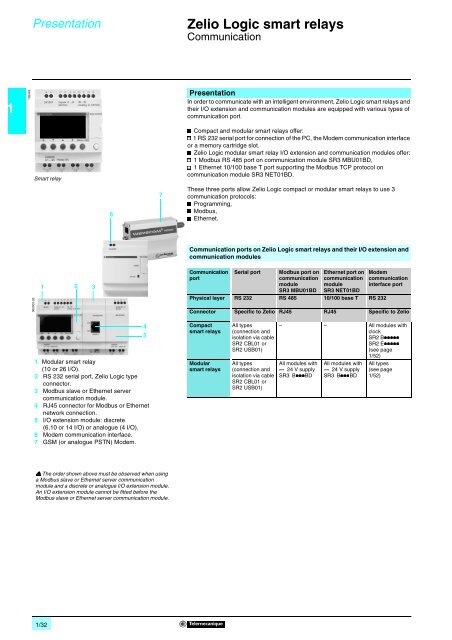
Presentation<br />
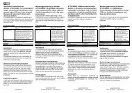
In order to communicate with an intelligent environment, <strong>Zelio</strong> <strong>Logic</strong> <strong>smart</strong> <strong>relays</strong> and<br />
their I/O extension and communication modules are equipped with various types of<br />
communication port.<br />
Smart relay<br />
6<br />
7<br />
1 Compact and modular <strong>smart</strong> <strong>relays</strong> offer:<br />
231 RS 232 serial port for connection of the PC, the Modem communication interface<br />
or a memory cartridge slot.<br />
1 <strong>Zelio</strong> <strong>Logic</strong> modular <strong>smart</strong> relay I/O extension and communication modules offer:<br />
231 Modbus RS 485 port on communication module SR3 MBU01BD,<br />
231 Ethernet 10/100 base T port supporting the Modbus TCP protocol on<br />
communication module SR3 NET01BD.<br />
These three ports allow <strong>Zelio</strong> <strong>Logic</strong> compact or modular <strong>smart</strong> <strong>relays</strong> to use 3<br />
communication protocols:<br />
1 Programming,<br />
1 Modbus,<br />
1 Ethernet.<br />
Communication ports on <strong>Zelio</strong> <strong>Logic</strong> <strong>smart</strong> <strong>relays</strong> and their I/O extension and<br />
communication modules<br />
000003-26<br />
1 2 3<br />
Communication<br />
port<br />
Serial port<br />
Modbus port on<br />
communication<br />
module<br />
SR3 MBU01BD<br />
Ethernet port on<br />
communication<br />
module<br />
SR3 NET01BD<br />
Physical layer RS 232 RS 485 10/100 base T RS 232<br />
Modem<br />
communication<br />
interface port<br />
Connector Specific to <strong>Zelio</strong> RJ45 RJ45 Specific to <strong>Zelio</strong><br />
4<br />
5<br />
1 Modular <strong>smart</strong> relay<br />
(10 or 26 I/O).<br />
2 RS 232 serial port, <strong>Zelio</strong> <strong>Logic</strong> type<br />
connector.<br />
3 Modbus slave or Ethernet server<br />
communication module.<br />
4 RJ45 connector for Modbus or Ethernet<br />
network connection.<br />
5 I/O extension module: discrete<br />
(6,10 or 14 I/O) or analogue (4 I/O).<br />
6 Modem communication interface.<br />
7 GSM (or analogue PSTN) Modem.<br />
Compact<br />
<strong>smart</strong> <strong>relays</strong><br />
Modular<br />
<strong>smart</strong> <strong>relays</strong><br />
All types<br />
(connection and<br />
isolation via cable<br />
SR2 CBL01 or<br />
SR2 USB01)<br />
All types<br />
(connection and<br />
isolation via cable<br />
SR2 CBL01 or<br />
SR2 USB01)<br />
– – All modules with<br />
clock<br />
SR2 B11111<br />
SR2 E11111<br />
(see page<br />
1/52)<br />
All modules with<br />
8724 V supply<br />
SR3 B111BD<br />
All modules with<br />
8724 V supply<br />
SR3 B111BD<br />
All types<br />
(see page<br />
1/52)<br />
1 The order shown above must be observed when using<br />
a Modbus slave or Ethernet server communication<br />
module and a discrete or analogue I/O extension module.<br />
An I/O extension module cannot be fitted before the<br />
Modbus slave or Ethernet server communication module.<br />
1/32
Description,<br />
characteristics 1<br />
<strong>Zelio</strong> <strong>Logic</strong> <strong>smart</strong> <strong>relays</strong> 1<br />
Communication<br />
Programming protocol<br />
Description<br />
524107<br />
1<br />
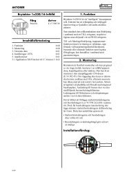
Link by cable<br />
1 Programming PC.<br />
2 RS 232 serial link cable (SR2 CBL01) or USB cable (SR2 USB01) (1).<br />
3 <strong>Zelio</strong> <strong>Logic</strong> compact or modular <strong>smart</strong> relay.<br />
1<br />
2<br />
3<br />
524106<br />
4<br />
Wireless link<br />
4 Programming PC with integrated Bluetooth technology (or Bluetooth adapter<br />
VW3 A8115 for PC not equipped with Bluetooth technology) (1).<br />
5 Bluetooth interface (SR2 BTC01) for <strong>Zelio</strong> <strong>Logic</strong> <strong>smart</strong> relay (1).<br />
6 <strong>Zelio</strong> <strong>Logic</strong> compact or modular <strong>smart</strong> relay.<br />
5<br />
524108<br />
7<br />
9<br />
10<br />
6<br />
Link by Modem<br />
7 Programming PC.<br />
8 Modem interface connecting cable supplied with SR2 COM01 (2).<br />
9 Modem for transmitting/receiving data SR2 MOD01 or SR2 MOD02 (2).<br />
10 Telephone or radio link.<br />
11 Communication interface SR2 COM01.<br />
12 <strong>Zelio</strong> <strong>Logic</strong> compact or modular <strong>smart</strong> relay.<br />
8<br />
9 12<br />
11<br />
(1) See page 1/26.<br />
(2) See page 1/52.<br />
Serial link characteristics<br />
Product type<br />
All <strong>Zelio</strong> <strong>Logic</strong> <strong>smart</strong> <strong>relays</strong><br />
Flow rate Kbit/s 115.2<br />
Data bits 7<br />
Stop bits 1<br />
Parity<br />
Pair<br />
Physical layer RS 232<br />
Type of connector<br />
Specific to <strong>Zelio</strong> <strong>Logic</strong><br />
1/33
Presentation,<br />
description 1<br />
<strong>Zelio</strong> <strong>Logic</strong> <strong>smart</strong> <strong>relays</strong> 1<br />
Communication<br />
Modbus slave communication protocol<br />
1<br />
532522 524121 524131<br />
Modbus communication module<br />
1<br />
7<br />
7<br />
8<br />
8<br />
4<br />
4<br />
6<br />
5<br />
7<br />
5bis<br />
4<br />
SR3 MBU01BD<br />
COM<br />
PWR<br />
MB485-V1<br />
1<br />
2<br />
2<br />
2<br />
3<br />
2<br />
4<br />
5<br />
3<br />
Presentation<br />
The Modbus communication protocol is of the master/slave type.<br />
Two exchange methods are possible:<br />
1 Request/reply:<br />
23The request from the master is addressed to a specific slave.<br />
23The master waits for the reply to be returned by the slave polled.<br />
1 Distribution:<br />
23The master distributes a request to all the slave stations on the bus.<br />
These stations execute the instruction without sending a reply.<br />
<strong>Zelio</strong> <strong>Logic</strong> modular <strong>smart</strong> <strong>relays</strong> are connected to the Modbus network via the<br />
Modbus slave communication module. This module is a slave that is not electrically<br />
isolated.<br />
The Modbus slave communication module must be connected to an SR3 B666BD<br />
modular <strong>smart</strong> relay, with a 5 24 V supply.<br />
Configuration<br />
The Modbus slave communication module can be configured:<br />
1 independently, using the buttons on the <strong>smart</strong> relay (1).<br />
1 on a PC, using “<strong>Zelio</strong> Soft 2” software, see page 1/9.<br />
When using a PC, programming can be performed either in LADDER language or in<br />
function block diagram (FBD) language, see pages 1/10 to 1/13.<br />
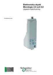
Connection example<br />
3 1 XBT N401 display unit.<br />
2 Modular <strong>smart</strong> relay SR3 B111BD.<br />
3 Modbus communication module SR3 MBU01BD.<br />
4 Modbus network (cables VW3 A8 306R66).<br />
5 Junction box TWD XCA T3RJ (polarisation and line end adapter activated).<br />
5bis Junction box TWD XCA T3RJ (line end adapter activated).<br />
6 T-junction 170 XTS 04100.<br />
3 7 T-junction VW3 A8 306TF66.<br />
Function description<br />
1 The Modbus slave communication module is connected to a 2-wire or 4-wire<br />
Modbus network (2).<br />
1 The maximum length of the network is 1000 m (9600 bauds max., AWG 26).<br />
1 A maximum of 32 slaves can be connected to the Modbus network, or a maximum<br />
of 247 slaves with repeaters.<br />
1 Line end adaptors must be fitted to both ends of the line<br />
(1 nF/10 V, 120 Ω /0.25 W in series).<br />
1 The line must be polarised (470 Ω /0.25 W resistors) (3).<br />
1 The connection cable and its RJ45 male connectors must be screened.<br />
1 The 7 terminal on the module must be connected directly to the protective earth<br />
at one point on the bus.<br />
(1) Programming from the front panel and buttons on the <strong>smart</strong> relay is only possible in LADDER<br />
language.<br />
(2) Please refer to installation instructions supplied with the product.<br />
(3) The polarisation resistors must be managed by the master.<br />
Description<br />
Modbus slave communication module SR3 MBU01BD comprises:<br />
1 Two retractable fixing lugs.<br />
2 A Modbus network connection (RJ45 screened female connector).<br />
3 A communication LED (COM).<br />
4 A “Power on” LED (PWR).<br />
5 A screw terminal block for the protective earth connection.<br />
6 A spring for clip-on mounting on a 35 mm mounting rail.<br />
7 Two locating pegs.<br />
8 Two locating pegs for clip-on fixing.<br />
6 1<br />
Characteristics:<br />
page 1/35<br />
Functions :<br />
page 1/36<br />
References :<br />
page 1/40<br />
Dimensions, mounting :<br />
page 1/41<br />
1/34
Characteristics 1<br />
<strong>Zelio</strong><br />
<strong>Logic</strong> <strong>smart</strong> <strong>relays</strong> 1<br />
Communication<br />
Modbus slave communication protocol<br />
Environment characteristics<br />
Type<br />
Product certifications<br />
Conformity with the<br />
low voltage directive<br />
Conformity with the<br />
EMC directive<br />
Conforming to 73/23/EEC<br />
SR3 MBU01BD<br />
UL, CSA, GL, C-TICK<br />
EN (IEC) 61131-2 (open equipment)<br />
Conforming to 89/336/EEC EN (IEC) 61131-2 (Zone B)<br />
EN (IEC) 61000-6-2, EN (IEC) 61000-6-3 (1) and EN (IEC) 61000-6-4<br />
Degree of protection Conforming to IEC/EN 60529 IP 20 (terminal block)<br />
IP 40 (front panel)<br />
Overvoltage category Conforming to IEC/EN 60664-1 3<br />
Degree of pollution Conforming to IEC/EN 61131-2 2<br />
Ambient air temperature<br />
around the device<br />
Conforming to<br />
IEC/EN 60068-2-1 and<br />
IEC/EN 60068-2-2<br />
Operation °C - 20... + 55 (+ 40 in non-ventilated enclosure)<br />
Storage °C - 40... + 70<br />
Max. relative humidity Conforming to IEC/EN 60068-2-30 95% without condensation or dripping water<br />
Maximum operating altitude Operation m 2000<br />
Transport m 3048<br />
Mechanical resistance Immunity to vibration IEC/EN 60068-2-6, test Fc<br />
Immunity to mechanical shock<br />
IEC/EN 60068-2-27, test Ea<br />
Resistance to<br />
electrostatic discharge<br />
Resistance to HF interference<br />
(immunity)<br />
Conducted and radiated<br />
emissions<br />
Earthing<br />
Immunity to<br />
electrostatic discharge<br />
Immunity to<br />
electromagnetic radiated fields<br />
IEC/EN 61000-4-2, level 3<br />
IEC/EN 61000-4-3<br />
Immunity to fast transients<br />
IEC/EN 61000-4-4, level 3<br />
in bursts<br />
Immunity to shock waves IEC/EN 61000-4-5<br />
Radio frequency<br />
IEC/EN 61000-4-6, level 3<br />
in common mode<br />
Voltage dips and breaks (6) IEC/EN 61000-4-11<br />
Immunity to damped<br />
IEC/EN 61000-4-12<br />
oscillation waves<br />
Conforming to EN 55022/11<br />
Class B (1)<br />
(Group 1)<br />
Yes (please refer to installation instructions supplied with the product).<br />
(1) Except for the configuration SR3 B111BD + SR3 MBU01BD + SR3 XT43BD class A (class B:<br />
work in progress).<br />
1<br />
Presentation, description :<br />
page 1/34<br />
Functions :<br />
page 1/36<br />
References :<br />
page 1/40<br />
Dimensions, mounting :<br />
page 1/41<br />
1/35
Functions 1<br />
<strong>Zelio</strong><br />
<strong>Logic</strong> <strong>smart</strong> <strong>relays</strong> 1<br />
Communication<br />
Modbus slave communication protocol<br />
1<br />
524121<br />
Parameter entry<br />
Parameters can be entered either using “<strong>Zelio</strong> Soft 2” software or directly using the<br />
buttons on the <strong>Zelio</strong> <strong>Logic</strong> <strong>smart</strong> relay (1).<br />
When the “RUN” instruction is given, the <strong>Zelio</strong> <strong>Logic</strong> <strong>smart</strong> relay initialises the<br />
Modbus slave communication module in a configuration previously defined in the<br />
basic program.<br />
The Modbus slave communication module has 4 parameters:<br />
1 number of UART wires and format of the frames on the Modbus network,<br />
1 transmission speed,<br />
1 parity,<br />
1 network address of the Modbus module.<br />
Software workshop<br />
parameter entry window<br />
The default parameter settings are as follows: 2-wire, RTU, 19 200 bauds, even<br />
parity, address n° 1.<br />
Parameter entry<br />
Options<br />
Number of wires 2 or 4<br />
Frame format<br />
RTU or ASCII<br />
Transmission speed<br />
1200, 2400, 4800, 9600, 19 200, 28 800, 38 400, 57 600<br />
in bauds<br />
Parity<br />
None, even, odd<br />
Network address 1 to 247<br />
Addressing of Modbus exchanges<br />
LADDER programming<br />
In LADDER mode, the 4 data words (16 bits) to be exchanged cannot be accessed<br />
by the application. Transfers with the master are implicit and are effected in a way<br />
that is totally transparent.<br />
524110<br />
Input words<br />
J1<br />
XT1<br />
J2<br />
XT1<br />
J3<br />
XT1<br />
3<br />
7<br />
2<br />
3<br />
7<br />
2<br />
Output words<br />
3<br />
0 9<br />
01<br />
7<br />
4<br />
2<br />
XT1<br />
4<br />
4<br />
3<br />
3<br />
3<br />
0 9<br />
0 9<br />
02<br />
XT1<br />
03<br />
XT1<br />
Modbus exchanges Code Number of words<br />
Image of <strong>smart</strong> relay I/O<br />
Read<br />
4<br />
03<br />
Clock words<br />
Status words<br />
Read/Write<br />
16, 06 or 03<br />
Read<br />
03<br />
Function block diagram (FBD) programming<br />
In FBD mode, the 4 input data words (16 bits) (J1XT1 to J4XT1) and the 4 output<br />
data words (O1XT1 to O4XT1) can be accessed by the application. Dedicated<br />
function blocks make it possible to:<br />
1 break down a ‘complete’ type input (16 bits) into 16 separate “bit” type outputs.<br />
23example: break down a J1XT1 to J4XT1 type input and copy these status values<br />
to discrete outputs.<br />
1 make up a ‘complete’ type output (16 bits) from 16 separate “bit” type inputs.<br />
23example: transfer the status value of the discrete inputs or the status of a function<br />
to an O1XT1 to O4XT1 type output.<br />
4<br />
1<br />
J4<br />
XT1<br />
3<br />
7<br />
2<br />
4<br />
3<br />
0 9<br />
04<br />
XT1<br />
Modbus exchanges Code Number of words<br />
Input words<br />
Read/Write<br />
4<br />
16, 06 or 03<br />
Output words<br />
Read<br />
03<br />
4<br />
Clock words<br />
Read/Write<br />
16, 06 or 03<br />
4<br />
Status words<br />
Read<br />
03<br />
1<br />
(1) Programming from the front panel and buttons on the <strong>smart</strong> relay is only possible in LADDER<br />
language.<br />
FDB program Editing window<br />
Presentation, description :<br />
page 1/34<br />
Characteristics:<br />
page 1/35<br />
References :<br />
page 1/40<br />
Dimensions, mounting :<br />
page 1/41<br />
1/36
Presentation,<br />
description 1<br />
<strong>Zelio</strong> <strong>Logic</strong> <strong>smart</strong> <strong>relays</strong> 1<br />
Communication<br />
Ethernet server communication protocol<br />
53631<br />
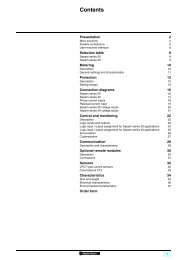
Presentation<br />
<strong>Zelio</strong> <strong>Logic</strong> modular <strong>smart</strong> <strong>relays</strong> are connected to the Ethernet network via the<br />
Ethernet server communication module.<br />
Communication module SR3 NET01BD allows communication on the Ethernet<br />
network under the Modbus TCP protocol.<br />
The Ethernet server communication module must be connected to an SR3 B666BD<br />
modular <strong>smart</strong> relay, with a 5 24 V supply.<br />
1<br />
Ethernet server<br />
communication module<br />
5<br />
6<br />
7<br />
Configuration<br />
The Ethernet server communication module is configured from a PC with "<strong>Zelio</strong> Soft"<br />
software, see page 1/9.<br />
On the PC, programming is effected in function block (FDB) language, see pages<br />
1/12 and 1/13.<br />
3<br />
2<br />
2<br />
4<br />
2 2<br />
1<br />
4<br />
8<br />
9<br />
8<br />
Connection example<br />
1 Twido client, 40 I/O compact base controller TWD LCAE 40DRF.<br />
2 Ethernet network (cables 490 NTW 00066).<br />
3 ConneXium 499 NES 251 00 Switch.<br />
4 <strong>Zelio</strong> <strong>Logic</strong> modular <strong>smart</strong> relay SR3 B666BD.<br />
5 Communication interface SR2COM01.<br />
6 Connecting cable SR2 CBL07 (supplied with the Modem communication<br />
interface).<br />
7 GSM (or analogue PSTN) Modem.<br />
8 Ethernet server communication module SR3 NET01BD.<br />
9 Analogue I/O extension module SR3 XT43BD.<br />
Function description<br />
1 The Ethernet server communication module is connected to a local LAN type<br />
network.<br />
1 The maximum cable length between 2 devices is 100 m.<br />
1 The connection cable must be at least category 5, and its RJ45 male connectors<br />
must be screened.<br />
1 The 7 terminal must be connected directly to the protective earth.<br />
4<br />
1<br />
8<br />
Description<br />
Ethernet server communication module SR3 NET01BD comprises:<br />
7<br />
7<br />
8<br />
SR3 NET01BD<br />
LK/ACT 10/100<br />
STS<br />
3<br />
2<br />
4<br />
1 Two retractable fixing lugs.<br />
2 An Ethernet network connection (RJ45 screened female connector).<br />
3 A communication LED (LK/ACT 10/100).<br />
4 A status LED (STS).<br />
5 A screw terminal block for the protective earth connection.<br />
6 A spring for clip-on mounting on a 35 mm mounting rail.<br />
7 Two locating pegs.<br />
8 Two locating pegs for clip-on fixing.<br />
8<br />
5<br />
6 1<br />
Characteristics:<br />
page 1/38<br />
Functions :<br />
page 1/39<br />
References :<br />
page 1/40<br />
Dimensions, mounting :<br />
page 1/41<br />
1/37
Characteristics 1<br />
<strong>Zelio</strong><br />
<strong>Logic</strong> <strong>smart</strong> <strong>relays</strong> 1<br />
Communication<br />
Ethernet server communication module<br />
1<br />
Environment characteristics<br />
Type<br />
Product certifications<br />
Conformity with the<br />
low voltage directive<br />
Conformity with the<br />
EMC directive<br />
Conforming to 73/23/EEC<br />
SR3 NET01BD<br />
UL, CSA, GL (pending), C-TICK (pending)<br />
EN (IEC) 61131-2 (open equipment)<br />
Conforming to 89/336/EEC EN (IEC) 61131-2 (Zone B)<br />
EN (IEC) 61000-6-2, EN (IEC) 61000-6-3 (1) and EN (IEC) 61000-6-4<br />
Degree of protection Conforming to IEC/EN 60529 IP 20 (terminal block)<br />
IP 40 (front panel)<br />
Overvoltage category Conforming to IEC/EN 60664-1 3<br />
Degree of pollution Conforming to IEC/EN 61131-2 2<br />
Ambient air temperature<br />
around the device<br />
Conforming to<br />
IEC/EN 60068-2-1 and<br />
IEC/EN 60068-2-2<br />
Operation °C 0... + 55 (+ 40 in non-ventilated enclosure)<br />
Storage °C - 40... + 70<br />
Max. relative humidity Conforming to IEC/EN 60068-2-30 95% without condensation or dripping water<br />
Maximum operating altitude Operation m 2000<br />
Transport m 3048<br />
Mechanical resistance Immunity to vibration IEC/EN 60068-2-6, test Fc<br />
Immunity to mechanical shock<br />
IEC/EN 60068-2-27, test Ea<br />
Resistance to<br />
electrostatic discharge<br />
Resistance to HF interference<br />
(immunity)<br />
Conducted and<br />
radiated emissions<br />
Earthing<br />
Immunity to<br />
electrostatic discharge<br />
Immunity to<br />
electromagnetic radiated fields<br />
IEC/EN 61000-4-2, level 3<br />
IEC/EN 61000-4-3<br />
Immunity to fast transients<br />
IEC/EN 61000-4-4, level 3<br />
in bursts<br />
Immunity to shock waves IEC/EN 61000-4-5<br />
Radio frequency<br />
IEC/EN 61000-4-6, level 3<br />
in common mode<br />
Voltage dips and breaks (6) IEC/EN 61000-4-11<br />
Immunity to damped<br />
IEC/EN 61000-4-12<br />
oscillation waves<br />
Conforming to EN 55022/11<br />
Class B(1)<br />
(Group 1)<br />
Yes (please refer to installation instructions supplied with the product).<br />
(1) Except for the configuration SR3 B111BD + SR3 NET01BD + SR3 XT43BD class A<br />
(class B: work in progress).<br />
Presentation, description :<br />
page 1/37<br />
Functions :<br />
page 1/39<br />
References :<br />
page 1/40<br />
Dimensions, mounting :<br />
page 1/41<br />
1/38
Functions 1<br />
<strong>Zelio</strong><br />
<strong>Logic</strong> <strong>smart</strong> <strong>relays</strong> 1<br />
Communication<br />
Ethernet server communication module<br />
Parameter entry<br />
Parameter entry must be carried out using “<strong>Zelio</strong> Soft 2” software.<br />
When the “RUN” instruction is given, the <strong>Zelio</strong> <strong>Logic</strong> <strong>smart</strong> relay initialises the<br />
Ethernet server communication module in a configuration previously defined in the<br />
basic program.<br />
1<br />
The Ethernet server communication module has 6 parameters:<br />
1 type of addressing (dynamic or static).<br />
1 IP address,<br />
1 sub-network mask,<br />
1 gateway address,<br />
1 reserved address,<br />
1 time out.<br />
Ethernet communication module configuration window<br />
Input words<br />
J1<br />
XT1<br />
J2<br />
XT1<br />
J3<br />
XT1<br />
J4<br />
XT1<br />
3<br />
0 01<br />
7 9<br />
2<br />
4 XT1<br />
3<br />
7<br />
2<br />
3<br />
7<br />
2<br />
3<br />
7<br />
2<br />
Output words<br />
4<br />
4<br />
4<br />
3<br />
3<br />
3<br />
3<br />
0 9<br />
0 9<br />
0 9<br />
02<br />
XT1<br />
03<br />
XT1<br />
04<br />
XT1<br />
Addressing of Ethernet exchanges<br />
Function block diagram (FBD) programming<br />
In FBD mode, the 4 input data words (16 bits) (J1XT1 to J4XT1) and the 4 output<br />
data words (O1XT1 to O4XT1) can be accessed by the application. Dedicated<br />
function blocks make it possible to:<br />
1 break down a ‘complete’ type input (16 bits) into 16 separate “bit” type outputs.<br />
23example: break down a J1XT1 to J4XT1 type input and copy these status values<br />
to discrete outputs.<br />
1 make up a ‘complete’ type output (16 bits) from 16 separate “bit” type inputs.<br />
23example: transfer the status value of the discrete inputs or the status of a function<br />
to an O1XT1 to O4XT1 type output.<br />
Ethernet exchanges Code Number of words<br />
Input words<br />
Read/Write<br />
4<br />
16, 06 or 03<br />
Output words<br />
Read<br />
4<br />
03<br />
Clock words<br />
Read/Write<br />
4<br />
16, 06 or 03<br />
Status words<br />
Read<br />
03<br />
1<br />
FDB program Editing window<br />
Presentation, description :<br />
page 1/37<br />
Characteristics:<br />
page 1/38<br />
References :<br />
page 1/40<br />
Dimensions, mounting :<br />
page 1/41<br />
1/39
References 1<br />
<strong>Zelio</strong><br />
<strong>Logic</strong> <strong>smart</strong> <strong>relays</strong> 1<br />
Communication<br />
1<br />
Modbus slave and Ethernet server communication modules<br />
For use with Network Reference Weight<br />
kg<br />
Modular <strong>smart</strong> <strong>relays</strong><br />
Modbus SR3 MBU01BD 0.110<br />
SR3 B22<br />
221BD and SR3 B22<br />
222BD (1)<br />
Ethernet SR3 NET01BD<br />
(2), (3)<br />
0.110<br />
SR3 MBU01BD<br />
Connection accessories<br />
Accessory Description Network Length Reference Weight<br />
m<br />
kg<br />
T-junctions 372 x RJ45 connectors Modbus 0.3 VW3 A8 306TF03 0.190<br />
371 cable with integrated<br />
RJ45 connector<br />
1 VW3 A8 306TF10 0.210<br />
SR3 NET01BD<br />
Junction<br />
boxes<br />
Line end<br />
adapter<br />
372 x RJ45 female<br />
connectors<br />
371 x RJ45 male connector<br />
Modbus Without<br />
cable<br />
170 XTS 04100 0.020<br />
37Screw terminal block Modbus – TWD XCA ISO 8 0.100<br />
for main cable<br />
371 x RJ45 connector<br />
for tap link<br />
37Isolation of RS 485<br />
serial link<br />
23Polarisation and<br />
line end adapter<br />
23Supply 5 24 V<br />
23Mounting on 35 mm<br />
9 rail<br />
373 x RJ45 connectors Modbus – TWD XCA T3RJ 8 0.080<br />
37Polarisation and line<br />
end adapter<br />
23Mounting on335 mm<br />
9 rail<br />
For RJ45 connector Modbus – VW3 A8306RC 0.200<br />
R = 120 Ω, C = 1 nf<br />
TWD XCA T3RJ<br />
RS 485<br />
cables<br />
Straight<br />
shielded<br />
twisted pair<br />
cable<br />
2 x RJ45 connectors Modbus 0.3 VW3 A8306R03 0.030<br />
1 VW3 A8306R10 0.050<br />
3 VW3 A8306R30 0.150<br />
2 x RJ45 connectors Ethernet 2 490 NTW 000 02 (4) –<br />
5 490 NTW 000 05 (4) –<br />
12 490 NTW 000 12 (4) –<br />
40 490 NTW 000 40 (4) –<br />
80 490 NTW 000 80 (4) –<br />
TWD XCA ISO<br />
conneXium – Ethernet 499 NES 251 00 0.190<br />
switch<br />
(1) Compatible with SR3 B11<br />
112BD featuring hardware version “H1.0.01”, available since June<br />
2005.<br />
(2) Can only be used in FBD language.<br />
(3) Can only be used with "<strong>Zelio</strong> Soft 2" software version 2 V 4.1.<br />
(4) Cable conforming to EIA/TIA-568 standard category 5 and IEC 1180/EN 50 173, class D.<br />
For UL and CSA 22.1 approved cables, add the letter U at the end of the reference.<br />
499 NES 251 00<br />
8 Available: 1 st quarter 2007<br />
Presentation, description :<br />
pages 1/34 to 1/37<br />
Characteristics:<br />
pages 1/35 to 1/38<br />
Functions :<br />
pages 1/36 to 1/39<br />
Dimensions, mounting :<br />
page 1/41<br />
1/40
Dimensions,<br />
mounting 1<br />
<strong>Zelio</strong> <strong>Logic</strong> <strong>smart</strong> <strong>relays</strong> 1<br />
Communication<br />
Communication modules SR3 01BD<br />
Common side view Rail mounting Screw mounting (retractable lugs)<br />
70<br />
1<br />
57<br />
52,5<br />
35<br />
35<br />
27.5<br />
108<br />
90<br />
35 27.5<br />
100<br />
44 15<br />
25<br />
2 x Ø4<br />
Presentation, description :<br />
pages 1/34 to 1/37<br />
Characteristics:<br />
pages 1/35 to 1/38<br />
Functions :<br />
pages 1/36 to 1/39<br />
References:<br />
page 1/40<br />
1/41