Parametric fire design - Steel-stainless.org
Parametric fire design - Steel-stainless.org
Parametric fire design - Steel-stainless.org

You also want an ePaper? Increase the reach of your titles
YUMPU automatically turns print PDFs into web optimized ePapers that Google loves.
Centre Technique Industriel<br />
de la Construction Métallique<br />
Domaine de Saint-Paul<br />
102, route de Limours<br />
F-78471 Saint-Rémy-lès-Chevreuse Cedex<br />
Tél : 33 (0)1 30 85 25 00 Fax : 33 (0)1 30 52 75 38<br />
cticm@cticm.com<br />
www.cticm.com<br />
Ref. Cticm<br />
SRI – 07/118 - CR/NB - Affair: 04-905<br />
Division : Fire Safety and Certification<br />
Section : Fire Research<br />
Tél : + 33 (0)1 30 85 25 23 Fax : + 33 (0)1 30 85 37 29<br />
E-Mail : chrenaud@cticm.com<br />
Contract RFS-04048 “Stainless <strong>Steel</strong> in Fire”<br />
WP 6 Final report<br />
September 20 th , 2007<br />
Author<br />
Christophe RENAUD<br />
Number of pages: 29<br />
Établissement certifié qualité ISO 9001 : 2000, le CTICM assure un suivi de chaque étude conformément à ses procédures qualité<br />
Membre du Comité de Coordination des Centres de Recherche en mécanique / Siret : 775 728 785 00038 Code Naf : 731Z
SRI – 07/118 – CR/NB<br />
September 20 th , 2007<br />
1. EXECUTIVE SUMMARY<br />
It is well known that <strong>stainless</strong> steel has excellent <strong>fire</strong> performances and then could be a very<br />
interesting solution for building applications where carbon steel would require <strong>fire</strong> protection. To<br />
investigate potential applications, numerical studies have been carried out on <strong>fire</strong> behaviour of both<br />
unprotected <strong>stainless</strong> steel members under natural <strong>fire</strong> conditions, such as columns in open car parks,<br />
and <strong>stainless</strong> steel members located outside the buildings. From obtained results, <strong>design</strong> rules for<br />
external <strong>stainless</strong> steel columns in <strong>fire</strong> as well as those in open car parks have been proposed.<br />
2/29
SRI – 07/118 – CR/NB<br />
September 20 th , 2007<br />
CONTENTS<br />
1. EXECUTIVE SUMMARY .................................................................................................................2<br />
CONTENTS...........................................................................................................................................3<br />
2. INTRODUCTION..............................................................................................................................4<br />
3. EXTERNAL STRUCTURES ............................................................................................................5<br />
3.1 NUMERICAL ANALYSIS........................................................................................................................5<br />
3.1.1 NUMERICAL ASSUMPTIONS ........................................................................................................................... 5<br />
3.1.2 INVESTIGATED PARAMETERS ....................................................................................................................... 8<br />
3.1.3 SUMMARY OF NUMERICAL RESULTS ........................................................................................................... 9<br />
4.2 DEVELOPMENT OF DESIGN GUIDANCE ..........................................................................................12<br />
4.2.1 MAIN FEATURES OF SIMPLE CALCULATION RULES................................................................................ 12<br />
4.2.2 COMPARISON OF RESULTS BETWEEN SIMPLE DESIGN RULES AND NUMERICAL MODEL .............. 13<br />
5. CAR PARK BUILDINGS................................................................................................................13<br />
5.1 FIRE ENGINEERING PROCEDURE APPLIED TO OPEN CARS PARKS ..........................................14<br />
5.2 NUMERICAL ANALYSIS OF OPEN CAR PARKS...............................................................................16<br />
5.2.1 INVESTIGATED OPEN CAR PARKS.............................................................................................................. 16<br />
5.2.2 PRELIMINARY DESIGN OF STAINLESS STEEL COLUMNS ....................................................................... 17<br />
5.2.3 MECHANICAL BEHAVIOUR OF CAR PARK STRUCTURES........................................................................ 20<br />
5.2.4 CONCLUSION.................................................................................................................................................. 28<br />
5.5 DEVELOPPEMENT OF DESIGN GUIDANCE......................................................................................28<br />
6. GENERAL CONCLUSIONS AND RECOMMANDATIONS FOR FURTHER WORK...................29<br />
7. REFERENCES...............................................................................................................................29<br />
3/29
SRI – 07/118 – CR/NB<br />
September 20 th , 2007<br />
2. INTRODUCTION<br />
The purpose of the present research work was to illustrate that <strong>stainless</strong> steel can become a practical<br />
alternative solution to protected structural carbon steel. So, different applications were investigated in<br />
which it is possible to use unprotected <strong>stainless</strong> steel, whereas carbon steel in the same application<br />
would require <strong>fire</strong> protection, such as external members or members submitted to natural <strong>fire</strong><br />
conditions. More exactly, it was selected to investigate:<br />
• the <strong>fire</strong> resistance of exposed <strong>stainless</strong> steel columns located outside buildings using a<br />
numerical modelling with help of the computer code ANSYS which was proved already to be in<br />
good agreement with several <strong>fire</strong> tests performed on <strong>stainless</strong> steel members [1]. Moreover,<br />
heating of external columns has been calculated from simple calculation methods developed in<br />
one previous ECSC Project “Development of <strong>design</strong> rules for the <strong>fire</strong> behaviour of external steel<br />
structures” (contract number 7210-PR-380) [2].<br />
• the <strong>fire</strong> behaviour of unprotected <strong>stainless</strong> steel columns in open car parks. This study has been<br />
performed on different framing systems (with unprotected carbon steel and concrete composite<br />
members) commonly used in France from a <strong>fire</strong> safety engineering procedure developed at<br />
CTICM and validated against experimental results [3, 9].<br />
From the results of these numerical studies, <strong>fire</strong> <strong>design</strong> guidance for both external columns as well as<br />
those in open car parks has been developed. The proposed <strong>design</strong> method for external <strong>stainless</strong> steel<br />
columns allows to calculate the ultimate buckling resistance using the appropriate buckling curve with<br />
the 0.2% proof characteristic strength. It has been shown through comparison with numerical results<br />
that the proposed calculation methods give an adequately safe prediction of the <strong>fire</strong> resistance of<br />
external columns. Design guidance established for <strong>stainless</strong> steel columns in open car parks gives the<br />
maximum load ratio of steel column to be used for standard framing systems of open car parks.<br />
The actual report describes numerical analyses, corresponding results and <strong>design</strong> guidance<br />
developed for investigated <strong>stainless</strong> steel members.<br />
4/29
SRI – 07/118 – CR/NB<br />
September 20 th , 2007<br />
3. EXTERNAL STRUCTURES<br />
3.1 NUMERICAL ANALYSIS<br />
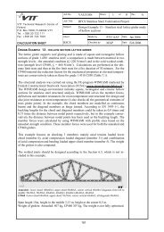
The <strong>fire</strong> behaviour of external <strong>stainless</strong> steel columns has been investigated using the computer<br />
package ANSYS for the current building configuration presented in Figure 1. It was supposed that the<br />
column was subjected to external flames from a <strong>fire</strong> compartment located at an intermediate level or at<br />
the top level of the building.<br />
beam perpendicular to<br />
the facade<br />
external beam parallel<br />
to the facade<br />
opening<br />
Slab<br />
external SHS<br />
column<br />
<strong>fire</strong> compartiment<br />
H=3m<br />
intermediate<br />
compartment<br />
facade<br />
H=3m<br />
Figure 1 : Details of investigated external columns<br />
3.1.1 Numerical assumptions<br />
Numerical simulations have been performed using the following assumptions:<br />
• Stainless steel column was modelled with non-linear beam-column element BEAM188.<br />
Column was meshed over a length of 9 m only (corresponding to the total height of 3<br />
successive levels) to take into account the favourable effect of column continuity on its <strong>fire</strong><br />
performance. Beams were not modelled. Only connections of column with horizontal steel<br />
beams were represented by appropriate boundary conditions restraining lateral displacements<br />
(restraining UX and UY) and rotation (ROTY and ROTZ) of column at the position of beams.<br />
Column ends were assumed to be hinged, so restraints were also applied to model the<br />
supports. Vertical load was applied on the column top. This load as its application direction<br />
(parallel to Z axis) was kept unchanged during the <strong>fire</strong> exposure (see Figure 2). An out-of–<br />
straightness of L/1000 was introduced in the modelling for geometrical imperfections.<br />
5/29
SRI – 07/118 – CR/NB<br />
September 20 th , 2007<br />
• The mechanical material properties of the column as a function of temperature have been<br />
taken to be in accordance with EN 1993-1-2, assuming the following mechanical properties at<br />
room temperature: f y = 240 N/mm², f u = 530 N/mm², E = 200,000 N/mm². Poisson ratio was<br />
taken as a constant value of 0.3.<br />
Lateral restrain<br />
conditions<br />
for beams<br />
Free end<br />
Restrained UX, UY,<br />
ROTY and ROTZ<br />
Column<br />
Exposed side<br />
S13<br />
S12<br />
S11<br />
S10<br />
S9<br />
S8<br />
S7<br />
S6<br />
S5<br />
S4<br />
S3<br />
S2<br />
S1<br />
9 m<br />
8.5 m<br />
8 m<br />
7.5 m<br />
7 m<br />
6.5 m<br />
6 m<br />
5.5 m<br />
5 m<br />
4.5 m<br />
4 m<br />
3.5 m<br />
3 m<br />
Restrained UX, UY, UZ,<br />
ROTY and ROTZ<br />
S1 0 m<br />
Free end<br />
a) modelled structure b) Temperature distribution along the column<br />
Figure 2: Detail of numerical modelling of column<br />
• A temperature gradient was introduced along the column length. This gradient was defined<br />
from temperature fields related to several cross-sections, assuming a linear variation of<br />
temperatures between these sections (see Figure 2). Each section was divided in four parts<br />
according to the column’s surface. The temperature field was then described by the evolution<br />
of three appropriate temperatures: the temperature of the exposed side, the temperature of<br />
the unexposed side and the temperature of the two intermediate sides.<br />
In our study, the heating of external <strong>stainless</strong> steel members were calculated using 2D simple<br />
calculation model developed in another ECSC Project “Development of <strong>design</strong> rules for the <strong>fire</strong><br />
behaviour of external steel structures” (contract number 7210-PR-380) which was proved already to<br />
give a sound estimation of transient heat fluxes to carbon external members during a <strong>fire</strong>. This model<br />
allowing only the prediction of thermal actions to external structure involves following three stages:<br />
• a zone model for the compartment <strong>fire</strong>,<br />
• an external flames model,<br />
• and the thermal actions calculation.<br />
For the first stage, any zone model capable of simulating fully developed <strong>fire</strong> can be used. Once<br />
temperature and heat flows through the opening are known, the second stage consists in estimating<br />
the properties of external flames by using the GER concept. The third stage is then devoted to the<br />
calculation of heat flux to structural member, using view factor for non engulfed member for example.<br />
To take account of bowing effect due to temperature gradient in mechanical analysis, a simplified 2D<br />
heat transfer model has been also developed. This model allows estimating the temperature<br />
development on rectangular hollow steel columns located outside a building when external thermal<br />
actions are known. As the focus is laid on steel section, the assumption of a thermally thin solid has<br />
been made in modelling. The hollow section is divided into four parts corresponding to its four sides,<br />
assuming a uniform temperature within each part. The heat balance of each part takes into account<br />
heat exchange with exterior (mainly thermal action from <strong>fire</strong>) as well as radiative balance between the<br />
four parts within the cavity. Heat conduction is neglected between the four sides of the section and<br />
along the column. Using heat fluxes as source data, the output data of this simplified 2D heat transfer<br />
are then the temperatures versus time of the four sides of the considered section. The combination of<br />
6/29
SRI – 07/118 – CR/NB<br />
September 20 th , 2007<br />
the above models makes it possible to get a quite good prediction of the thermal behaviour of hollow<br />
steel sections located outside a compartment during a <strong>fire</strong>.<br />
φ inc,1<br />
T 1<br />
φ inc,2<br />
T 2<br />
Radiative<br />
equilibrium<br />
T 4<br />
T 3<br />
φ inc,4<br />
φ inc,3<br />
Figure 3: Principle of simplified 2D heat transfer model for hollow steel section<br />
It should be noticed that simple methods developed for thermal analysis have been validated in case<br />
of <strong>stainless</strong> steel members against results given by advanced numerical models. A validation case<br />
study was proposed, on the basis of an experimental test performed by CTICM on external steel<br />
column exposed to a compartment natural <strong>fire</strong>. This test was carried out on a steel assembly<br />
composed of insulated beam (5m long) in a <strong>fire</strong> room and a steel column (4m long) located outside of<br />
the compartment (at 545 mm from the façade of external wall) but in front of the opening of the room.<br />
From this configuration, heating of one external square hollow steel column (300x8mm) has been<br />
calculated with previous models and compared to the temperature distribution obtained for the same<br />
column by a Computational Fluid Dynamics analysis (allowing to determine thermal actions) combined<br />
with a heat transfer analysis using advanced calculation model. In our study, the computer package<br />
ANSYS was employed.<br />
Structural details of the case study are reported in the following figure.<br />
Hollow <strong>Steel</strong> column<br />
(300x8mm)<br />
roof of<br />
furnace<br />
zone 3<br />
zone 2<br />
5.0 m<br />
1.5 m 2.0 m 1.5 m<br />
zone 1<br />
20m<br />
column<br />
beam<br />
opening<br />
545<br />
mm<br />
1.47 m<br />
1.36 m 0.3<br />
20m<br />
Figure 4: Details of case study<br />
The temperatures on the hollow steel column have been calculated at level of seven sections (see<br />
Figure 5). For each section, four temperature rises (one per face) have been predicted.<br />
7/29
SRI – 07/118 – CR/NB<br />
September 20 th , 2007<br />
Hollow steel<br />
section<br />
z [m]<br />
5.34 m<br />
Front wall<br />
S1<br />
4.34 m<br />
Internal ceiling<br />
l l<br />
S BeamInt<br />
3 m<br />
S BeamExt<br />
S4<br />
S2<br />
S6<br />
S5<br />
3.84 m<br />
3.34 m<br />
3.09 m<br />
2.84 m<br />
S3<br />
2.34 m<br />
1.47 m<br />
z<br />
Front wall<br />
1.34 m<br />
y<br />
1.8<br />
3.65 4.1 4.5<br />
3.85 4.3<br />
x [m]<br />
Figure 5: Sections distributions<br />
As example, the following figure presents the temperature rises predicted in the steel column section<br />
S5. These temperatures are compared to the temperature distribution obtained for the same column<br />
by detailed numerical analyse (FDS + ANSYS). It can be noted that temperatures obtained from<br />
simple models are in good agreement with advanced numerical simulations.<br />
Temperature (°C)<br />
800<br />
700<br />
600<br />
500<br />
400<br />
300<br />
3<br />
1<br />
2<br />
4 1<br />
2,3<br />
4<br />
200<br />
100<br />
FDS + ANSYS<br />
Simplified methods<br />
0<br />
0 400 800 1200 1600 2000 2400<br />
Time (s)<br />
Figure 6: Temperatures rises in hollow steel column<br />
3.1.2 Investigated parameters<br />
Mechanical behaviour of external <strong>stainless</strong> steel columns has been assessed by varying the main<br />
parameters affecting the <strong>fire</strong> severity, the <strong>fire</strong> performance of columns. More exactly, main parameters<br />
adopted in parametric study were the following:<br />
• Compartment sizes: 3 sizes, namely 3m×4m , 6m×4m and 9m×8m;<br />
8/29
SRI – 07/118 – CR/NB<br />
September 20 th , 2007<br />
• Wall thermal properties: Density ρ=1000 kg/m 3 , specific heat C=800J/KgK, thermal<br />
conductivity λ=0.5 W/mK, wall emissivity ε w =0.9, wall thickness e w =0.2m;<br />
• External member location: 2 locations in front of the opening: 0.5m (engulfed in <strong>fire</strong>) and 1.5m<br />
from the compartment;<br />
• Total area of windows: 25 %, 50 % and 100% of the façade area;<br />
• Fire load density: 500, 750, 1000 and 1500 MJ/m²;<br />
• External members: Square hollow section columns with cross-section ranging form 100 to<br />
300mm and <strong>stainless</strong> steel grade EN1.4401;<br />
• Load level of column: ranging from 0.1 to 0.7 (the load level is based on the <strong>design</strong> resistance<br />
of the members according to EN 1993-1-1 <strong>design</strong> rules);<br />
3.1.3 Summary of numerical results<br />
The results of this parametric study are quite numerous. Nevertheless, some representative results<br />
are given hereafter.<br />
As example, Figure 7 show temperature developments calculated for the SHS column 150x8mm<br />
engulfed in <strong>fire</strong> assuming a compartment of 3m width and 4.0 m, a <strong>fire</strong> load of 1500MJ/m² and an<br />
opening of 50%. It illustrates very well one of the main features of the heating conditions of external<br />
steel members, namely strong thermal gradients along and across the section. For example:<br />
• Across the section of the column, temperature differences can easily reach 400°C to 500°C with<br />
reference temperature of 1000°C between both exposed and unexposed sides.<br />
• Along the column, thermal gradient over the height can be about 500°C/m.<br />
The most severe cross-sectional temperatures obtained at failure of some investigated cases are<br />
given in Table 1 It can be seen from this table that <strong>stainless</strong> steel columns have a mean temperature<br />
higher than 550°C at failure. Obviously the column temperatures at failure increases with lower load<br />
levels. Moreover, it is clear that the use of unprotected external <strong>stainless</strong> steel columns is fully<br />
possible if the load level is lower than 0.5.<br />
To confirm advantages of external columns in <strong>stainless</strong> steel with regard to the <strong>fire</strong> resistance,<br />
additional calculations have been made with S235 carbon steel column without any applied <strong>fire</strong><br />
protection (see Table 2). It can be seen that carbon steel columns already failed before 30 minutes<br />
where <strong>stainless</strong> steel column can remain stable during whole <strong>fire</strong> duration.<br />
9/29
SRI – 07/118 – CR/NB<br />
September 20 th , 2007<br />
Temperature (°C)<br />
250.00<br />
Temperature (°C)<br />
1000.00<br />
200.00<br />
Tmax<br />
Tint<br />
Tmin<br />
900.00<br />
800.00<br />
700.00<br />
Tmax<br />
Tint<br />
Tmin<br />
150.00<br />
600.00<br />
500.00<br />
100.00<br />
400.00<br />
300.00<br />
50.00<br />
200.00<br />
100.00<br />
0.00<br />
0.00<br />
0.00 20.00 40.00 60.00 80.00 100.00 120.00<br />
0.00 20.00 40.00 60.00 80.00 100.00 120.00<br />
Time (min)<br />
Time (min)<br />
a) Z=3.5m b) Z=4.5m<br />
Temperature (°C)<br />
Temperature (°C)<br />
1000.00<br />
1200.00<br />
900.00<br />
800.00<br />
700.00<br />
Tmax<br />
Tint<br />
Tmin<br />
1000.00<br />
800.00<br />
Tmax<br />
Tint<br />
Tmin<br />
600.00<br />
500.00<br />
600.00<br />
400.00<br />
300.00<br />
400.00<br />
200.00<br />
200.00<br />
100.00<br />
0.00<br />
0.00<br />
0.00 20.00 40.00 60.00 80.00 100.00 120.00<br />
0.00 20.00 40.00 60.00 80.00 100.00 120.00<br />
Time (min)<br />
Time (min)<br />
c) Z=5m d) Z=5.5m<br />
Temperature (°C)<br />
Temperature (°C)<br />
700.00<br />
450.00<br />
600.00<br />
500.00<br />
Tmax<br />
Tint<br />
Tmin<br />
400.00<br />
350.00<br />
300.00<br />
Tmax<br />
Tint<br />
Tmin<br />
400.00<br />
250.00<br />
300.00<br />
200.00<br />
200.00<br />
150.00<br />
100.00<br />
100.00<br />
50.00<br />
0.00<br />
0.00 20.00 40.00 60.00 80.00 100.00 120.00<br />
Time (min)<br />
0.00<br />
0.00 20.00 40.00 60.00 80.00 100.00 120.00<br />
Time (min)<br />
Temperature (°C)<br />
250.00<br />
e) Z=6m f) Z=6.5m<br />
Temperature (°C)<br />
70.00<br />
200.00<br />
Tmax<br />
Tint<br />
Tmin<br />
60.00<br />
50.00<br />
Tmax<br />
Tint<br />
Tmin<br />
150.00<br />
40.00<br />
100.00<br />
30.00<br />
50.00<br />
20.00<br />
10.00<br />
0.00<br />
0.00<br />
0.00 20.00 40.00 60.00 80.00 100.00 120.00<br />
0.00 20.00 40.00 60.00 80.00 100.00 120.00<br />
Time (min)<br />
Time (min)<br />
g) h=7m h) h=7.5m<br />
Figure 7: Example of temperature development in SHS column 150x8mm<br />
10/29
SRI – 07/118 – CR/NB<br />
September 20 th , 2007<br />
Table 1: Temperatures field at failure of some external columns with <strong>stainless</strong> steel engulfed in <strong>fire</strong><br />
Cross-section<br />
Compartment Size: 3×4m<br />
(<strong>fire</strong> load density 1500MJ and<br />
50% of windows opening)<br />
Compartment Size: 9×8m<br />
(Fire load density 1500MJ<br />
and 50% of windows opening)<br />
η fi,t =0.3 η fi,t =0.5 η fi,t =0.7 η fi,t =0.3 η fi,t =0.5 η fi,t =0.7<br />
T max (exposed side) N.F* 980 870 N.F* 921 813<br />
RHS 150x8<br />
T int (intermediate side) N.F* 738 566 N.F* 783 690<br />
T min (unexposed side) N.F* 534 234 N.F* 361 214<br />
T mean = (T max +2T int +T min )/4 - 748 559 - 712 602<br />
Failure time (min) - 38.2 15.3 - 20.4 14.7<br />
RHS 300x8<br />
T max (exposed side) N.F* N.F* 883 N.F* 945 833<br />
T int (intermediate side) N.F* N.F* 576 N.F* 802 696<br />
T min (unexposed side) N.F* N.F* 242 N.F* 392 208<br />
T mean = (T max +2T int +T min )/4 - - 571 - 735 596<br />
Failure time (min) - - 15.8 - 22.4 15<br />
* Column remains stable during all <strong>fire</strong> exposure<br />
η fi,t is the load level under <strong>fire</strong> situation<br />
Table 2: Temperatures field at failure of some external columns with carbon steel engulfed in <strong>fire</strong><br />
Cross-section<br />
Compartment Size: 3×4m<br />
(<strong>fire</strong> load density 1500MJ and<br />
50% of windows opening)<br />
Compartment Size: 9×8m<br />
(Fire load density 1500MJ<br />
and 50% of windows opening)<br />
η fi,t =0.3 η fi,t =0.5 η fi,t =0.7 η fi,t =0.3 η fi,t =0.5 η fi,t =0.7<br />
T max (exposed side) 908 602 467 877 686 538<br />
RHS 150x8<br />
T int (intermediate side) 768 601 514 709 586 503<br />
T min (unexposed side) 451 115 75 320 177 125<br />
T mean =(T max +2T int +T min )/4 699 480 392 654 509 417<br />
Failure time (min) 25.1 9.9 7.8 11.2 8.7 7.6<br />
RHS 300x8<br />
T max (exposed side) 794 593 423 862 600 449<br />
T int (intermediate side) 750 583 481 700 539 448<br />
T min (unexposed side) 390 106 63 293 132 91<br />
T mean = (T max +2T int +T min )/4 670 471 362 623 434 339<br />
Failure time (min) 20.1 8.7 6.6 10.8 8.0 7.0<br />
* Column remains stable during all <strong>fire</strong> exposure<br />
η fi,t is the load level under <strong>fire</strong> situation<br />
11/29
SRI – 07/118 – CR/NB<br />
September 20 th , 2007<br />
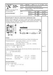
4.2 DEVELOPMENT OF DESIGN GUIDANCE<br />
4.2.1 Main features of simple calculation rules<br />
The buckling resistance of <strong>stainless</strong> steel external columns under axial compression (class of cross<br />
section ≤ 3) in the <strong>fire</strong> situation can be obtained from:<br />
where:<br />
4<br />
b ,fi,t,Rd<br />
= χfi(<br />
). ∑A i.f2,<br />
θi<br />
/<br />
i=<br />
1<br />
N λ θ<br />
γ<br />
(1)<br />
Mfi<br />
• A i is the area of plane element i defining the hollow cross-section (exposed side, lateral side or<br />
unexposed side);<br />
• θ i is the temperature of plane element i calculated from the simplified 2D heat transfer model<br />
developed for hollow steel section;<br />
• f 2,θi is the 2% proof characteristic strength at temperature θ i ;<br />
• γ M,fi is the partial factor for the <strong>fire</strong> situation;<br />
• λ is the non dimensional slenderness at elevated temperature θ;<br />
θ<br />
• χ fi is the reduction factor for flexural buckling in the <strong>fire</strong> <strong>design</strong> situation obtained from an<br />
appropriate buckling curve and depending on the non-dimensional slenderness:<br />
The reduction factor χ fi for buckling resistance in the <strong>fire</strong> <strong>design</strong> situation is determined according to:<br />
χ<br />
fi<br />
=<br />
1<br />
with χ f i ≤ 1.0 (1)<br />
2<br />
ϕ + ϕ −λ<br />
θ<br />
θ<br />
2<br />
θ<br />
235 2<br />
With help of the buckling curve defined in EN 1993-1-2, there is ϕ<br />
θ<br />
= 0,5(1 + 0,65λ<br />
θ + λ θ ) .<br />
fy<br />
The non dimensional slenderness λ at temperature θ is given by:<br />
θ<br />
∑<br />
λ A f / N<br />
(2)<br />
θ =<br />
i<br />
i<br />
y, θi<br />
fi,cr<br />
where N fi,cr is the Euler elastic critical load effective flexural stiffness obtained from:<br />
N<br />
fi,cr<br />
2<br />
2<br />
= π (EI)<br />
eff<br />
/ lθ<br />
(3)<br />
Where l θ is an equivalent buckling length in <strong>fire</strong> situation taking into account effects of thermal gradient<br />
and column continuity on the <strong>fire</strong> resistance of the column. For an intermediate storey the buckling<br />
length l θ of a continuous column may be taken as l θ = L – h s (with h s the height of sill) and at the top<br />
storey the buckling length may be taken as l θ = L, where L is the system length in the relevant storey.<br />
The effective rigidity, (EI) fi,eff , is determined as follows:<br />
∑<br />
= . I<br />
(4)<br />
( EI)<br />
fi,eff<br />
E.<br />
i, θ<br />
i<br />
i<br />
where:<br />
• E i,θ is the modulus of elasticity of plate element i at the appropriate elevated temperature θ i ;<br />
• I i is the second moment of area of plate element i;<br />
Obviously, checking of the external column consists in satisfying the condition:<br />
N fi,Ed ≤ N fi,Rd (5)<br />
where N fi,Ed is the <strong>design</strong> value of the axial compression for the combination of actions considered in<br />
<strong>fire</strong> situation (according to EN 1991-1-2).<br />
12/29
SRI – 07/118 – CR/NB<br />
September 20 th , 2007<br />
4.2.2 Comparison of results between simple <strong>design</strong> rules and numerical model<br />
To show the accuracy of the simple calculation method described in the previous paragraph, for all<br />
members investigated in our parametric study, critical temperatures calculated with simple calculation<br />
rules and those obtained numerically with the computer code ANSYS have been compared. It has to<br />
be noted here that the critical temperature of <strong>stainless</strong> steel columns is defined as the mean<br />
temperature obtained from the more severe temperature distribution over the column cross-section at<br />
failure. Moreover, comparison between the above two approaches is based on the load level derived<br />
from <strong>design</strong> resistance so the same absolute load values. The reason of doing so is that the applied<br />
load under <strong>fire</strong> situation will be based on simplified calculation rules only.<br />
The results of such comparison are illustrated in Figure 8, with the numerical results on X-axis and the<br />
simplified calculation results on Y-axis. It can be seen that simplified calculation rules agree quite well<br />
with the numerical model. The difference between the simplified calculation rules and the numerical<br />
model does not exceed 10 %, with some points on the unsafe side.<br />
Tcrit MS (°C)<br />
1200.0<br />
Compartment size 3x4m<br />
1000.0<br />
Compartment size 9x8m<br />
+10%<br />
800.0<br />
-10%<br />
600.0<br />
400.0<br />
200.0<br />
0.0<br />
0.0 200.0 400.0 600.0 800.0 1000.0 1200.0<br />
Tcrit ANSYS (°C)<br />
Figure 8: Comparison of critical temperatures calculated using simplified method (T crit MS) and<br />
numerical model (T crit ANSYS)<br />
In conclusion, the proposed simple calculation rules (combining a simplified 2D heat transfer model to<br />
calculate the temperatures versus time of the four sides of the hollow section with the previous<br />
mechanical model) are fully suitable to predict with a good precision the <strong>fire</strong> resistance of external<br />
<strong>stainless</strong> steel members under axial compression.<br />
5. CAR PARK BUILDINGS<br />
Another aim of this project research was to investigate the potential application of unprotected<br />
<strong>stainless</strong> steel members under localised natural <strong>fire</strong> conditions. In this purpose, it has been proposed<br />
to study the behaviour of steel and concrete composite structures of open car parks with <strong>stainless</strong><br />
steel columns using a <strong>fire</strong> safety engineering procedure developed in France and validated against<br />
experimental results. In fact, this engineering procedure was already applied to open car parks with<br />
unprotected carbon steel and concrete composite structures. It led to the establishment of <strong>design</strong><br />
guidance giving the minimum size of unprotected carbon steel members as well as the maximum load<br />
ratio of carbon steel column to be used for different framing systems commonly used in open car parks<br />
in France. Adopting the same framing systems, numerical investigations have permitted to define the<br />
maximum load level for unprotected columns with <strong>stainless</strong> steel hollow section.<br />
13/29
SRI – 07/118 – CR/NB<br />
September 20 th , 2007<br />
In following section, the principle of above mentioned <strong>fire</strong> engineering procedure applied to open car<br />
parks and main corresponding results are given.<br />
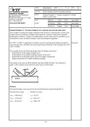
5.1 FIRE ENGINEERING PROCEDURE APPLIED TO OPEN CARS PARKS<br />
The <strong>fire</strong> behaviour of open car parks has been investigated according to a <strong>fire</strong> engineering procedure<br />
based on natural <strong>fire</strong> concept and composed of following steps:<br />
• Determination of the most unfavourable <strong>fire</strong> scenarios with respect to the <strong>fire</strong> stability of the<br />
structure and according to the arrangement of car park position (number of cars involved in<br />
<strong>fire</strong> and their positions). In theory, the <strong>fire</strong> behaviour of open car parks should be checked<br />
under the three basic <strong>fire</strong> scenarios indicated on Figure 9. These scenarios consider that<br />
seven vehicles on the same parking line, four vehicles in two successive parking lines or only<br />
one vehicle at any position of car park are involved in <strong>fire</strong>. However, according to the objective<br />
of actual study, only one <strong>fire</strong> scenario in relation to four vehicles is considered in the present<br />
study. This <strong>fire</strong> scenario assumes that a column is engulfed fully in a <strong>fire</strong> of four vehicles<br />
around. The <strong>fire</strong> starts in one of four vehicles and spreads to three vehicles around. The<br />
vehicles are in class 3 (which corresponds to model of type Laguna, Mondeo, Passat, Vectra,<br />
etc) except one of the vehicles which is of type utilitarian. In this case, its heat release is much<br />
more important.<br />
colum<br />
T = 36 min – 3b<br />
Scenario 2<br />
T = 24 min – 2b<br />
T = 12 min – 1b<br />
T = 0.0 min - 0<br />
T = 12 min – 1b<br />
T = 0.0 min - 0<br />
T = 12 min – 1b<br />
T = 12 min – 1a<br />
T = 12 min – 1a<br />
T = 24 min – 2a<br />
T = 24 min – 2a<br />
T = 36 min – 3a<br />
main beam<br />
Scenario 3<br />
Scenario 1<br />
secondary beam<br />
Class 3 vehicle<br />
Utilitary<br />
Figure 9: Basic <strong>fire</strong> scenario for open car parks<br />
• Evaluation of thermal actions as a function of time applied to different structural members<br />
according to the <strong>fire</strong> scenario and corresponding <strong>fire</strong> development based on the heat release<br />
rate of different vehicles as well as the propagation of <strong>fire</strong> between them. For open car parks,<br />
structural members near <strong>fire</strong> are generally subjected to heat flux derived from <strong>fire</strong> flames while<br />
structural members far from <strong>fire</strong> will be only heated slightly by the layer of hot gas. Therefore,<br />
in some case the thermal action for structural members will be the combination of both of<br />
them, As example, Figure 10 shows the heat release rate of four vehicles involved in <strong>fire</strong><br />
14/29
SRI – 07/118 – CR/NB<br />
September 20 th , 2007<br />
Heat realase heat (MW)<br />
35<br />
30<br />
25<br />
20<br />
15<br />
10<br />
5<br />
0<br />
0 10 20 30 40 50 60 70 80 90<br />
Time(min)<br />
Figure 10: Heat release rate of 4 vehicles involved in <strong>fire</strong><br />
• Estimation of heating of structural members considering possible temperature gradient not<br />
only on the cross section but also along the member’s length. It has been noted that this<br />
analysis needs to use advanced calculation model. In the present study, the computer code<br />
ANSYS has been employed. The four main structural members and corresponding finite<br />
element mesh are illustrated in Figure 11. Only one half of the composite slab and one quarter<br />
of the column was modelled to reduce the size of the model. Each structural member was<br />
considered to be thermally independent and its connection with other members was<br />
neglected.<br />
a) Composite slab b) beams<br />
c) Hollow steel column (1/4 of the<br />
cross-section)<br />
Figure 11: Meshing of main structural members for thermal analysis<br />
• Calculation of mechanical behaviour of car park structure based on a 3D numerical modelling<br />
with previously predicted structural heating. This global analysis allows taking into account<br />
lateral buckling of steel beams, membrane and diaphragm effects on the floor and load<br />
redistributions from the heated part of the structure to cold parts. In our parametric study, the<br />
computer package ANSYS has been also employed using different types of finite elements in<br />
modelling. As shown in Figure 12, the fact to have a locally heated part of the structure gives<br />
the possibility of modelling only a small part of the car park. The reason of this modelling<br />
strategy is to reduce to minimum the computation cost which becomes very important if a<br />
large area of floor is taken into account. In this case, the influence of remained part of the<br />
structure is represented by appropriate boundary conditions. Details of numerical modelling<br />
are also given in Figure 12. In this modelling, following four types of finite elements have been<br />
used: 3D non-linear line element - BEAM24, 3D non-linear line element beam 188, 3D nonlinear<br />
multi-layer shell element – SHELL91 and 3D linear line element – PIPE16. In particular,<br />
15/29
SRI – 07/118 – CR/NB<br />
September 20 th , 2007<br />
it can be underlined that the composite floor is represented by following finite elements: shell<br />
element for solid part of composite slab as well as reinforcing steel grid; beam-column<br />
element for steel members, steel sheet and ribs of composite slab and rigid link element for<br />
full connection between steel beams and composite slab. Moreover, because it is only a part<br />
of the structure, there are some restrained conditions from non-modelled part of the structure<br />
to be taken into account. These restrained conditions are represented by equivalent boundary<br />
conditions: fully fixed column bases due to continuous column condition and lower floor<br />
staying cold and rotation and lateral displacement restrained slab because of the continuity<br />
condition of the slab. Another important aspect to be mentioned here is the material<br />
mechanical properties at elevated temperatures. In our study, recommendations given in EN<br />
1994-1-2 for this feature are followed closely for steel and concrete. In addition, the concrete<br />
is considered as strength irreversible material which means that as far as it is highly heated it<br />
will not recover its initial strength during the cooling phase. This material property is certainly<br />
closer to reality and has to be taken into account in order to obtain realistic structure behaviour<br />
in natural <strong>fire</strong> condition. Although the numerical modelling given above is already quite<br />
complicated, it is still necessary to check some specific features which are not included in<br />
numerical model such as the possible rupture of reinforcing steel due to too important<br />
elongation or the movement of vehicles, if deflection of floor becomes too high, modifying<br />
initial loading condition of floor. As a consequence, two special criteria have been<br />
systematically checked for numerical results of all structure frames, which correspond to:<br />
• maximum mechanical strain of reinforcing steel not exceeding 5%<br />
• maximum deflection of floor not higher than 20 th of secondary beam span<br />
Restrained rotation and<br />
translation to simulate<br />
continuous slab<br />
SHELL91: solid part of<br />
concrete slab<br />
Heated part of<br />
the structure<br />
BEAM188:<br />
steel column<br />
Cold part of<br />
the structure<br />
PIPE16: connexion<br />
between steel beam<br />
and concrete slab<br />
BEAM24: steel<br />
beam, steel<br />
sheet, and<br />
concrete rib<br />
a) Modelled structure Detail of numerical modelling<br />
Figure 12: Example of modelled structure and boundary conditions<br />
5.2 NUMERICAL ANALYSIS OF OPEN CAR PARKS<br />
5.2.1 Investigated open car parks<br />
Two different structures corresponding to standard framing systems commonly used in open car parks<br />
in France were investigated in our study. They correspond to two-level steel and concrete composite<br />
structures composed of composite floor system (steel beams connected with composite slab) and<br />
steel column partially protected by concrete (see Figure 13). The structural detail of these standard<br />
frame systems using carbon steel are reported in table 1. For this structure, the length direction of<br />
parking places is parallel to secondary beams.<br />
16/29
SRI – 07/118 – CR/NB<br />
September 20 th , 2007<br />
Frame structure Case 1 Case2<br />
Level height (m)<br />
Cross section of<br />
members<br />
(standard level)<br />
First level 4.10 3.10<br />
Second level 2.67 2.67<br />
Column<br />
Main beam<br />
Secondary beam<br />
HEB 240<br />
(S355)<br />
HEA 500<br />
(S355)<br />
IPE 500<br />
(S355)<br />
HEA 340<br />
(S355)<br />
IPE 400<br />
(S355)<br />
IPE 240<br />
(S355)<br />
Composite slab Cofraplus60 Cofraplus60<br />
Span of secondary beams (m) 15 7.5<br />
spacing of secondary beams (m) 3.33 2.50<br />
Width of parking place (m) 2.5 2.5<br />
Number of vehicles between two<br />
successive secondary beams<br />
1 1<br />
Spacing of columns (m) 10.0 7.50<br />
Span of main beams (m) 10.0 7.50<br />
Total depth of concrete slab (cm) 12 12<br />
Table 3: Summary of studied structure frame systems<br />
composite slab (full connection<br />
between steel beams and<br />
concrete slab)<br />
HEA 500<br />
3.33 m<br />
IPE550<br />
3.2 m<br />
beams are I or H hot<br />
rolled steel sections<br />
4.2 m<br />
IPE550<br />
15 m<br />
10 m<br />
Columns are I or<br />
H hot rolled steel<br />
sections steel<br />
HEB 240 HEB 240<br />
a) first standard structure frame b) Corresponding steel frames<br />
Figure 13: Detail of the first standard frame systems of open car parks<br />
5.2.2 Preliminary <strong>design</strong> of <strong>stainless</strong> steel columns<br />
Before starting the analysis of the <strong>fire</strong> behaviour of the two selected car park structures, preliminary<br />
calculations have been carried out to <strong>design</strong> the minimum CHS columns with <strong>stainless</strong> steel (leading<br />
to the maximum load ratio available with <strong>stainless</strong> steel) to be used in place of hot rolled H carbon<br />
steel columns given in Table 3. This <strong>design</strong> has been made as follows:<br />
1. Evaluation of a <strong>stainless</strong> steel column having the same buckling resistance at room<br />
temperature <strong>design</strong> than the partially encased carbon steel section used in open car park. In<br />
17/29
SRI – 07/118 – CR/NB<br />
September 20 th , 2007<br />
case of investigated open car parks, the load level of carbon steel columns is 0.35.<br />
2. Determination of the temperature development in the <strong>stainless</strong> steel column (considering<br />
temperature gradient along the member's length) and estimation of the column buckling<br />
resistance as function of time for the critical cross-sectional temperature previously obtained.<br />
In fact, these results give the maximum load level (defined as the ratio of the <strong>fire</strong> buckling<br />
resistance over the ultimate load at room temperature <strong>design</strong>) available for columns.<br />
3. Design of the <strong>stainless</strong> steel column cross-section so that the column load level (defined as<br />
the ratio of the applied load under <strong>fire</strong> situation over the ultimate load at room temperature<br />
<strong>design</strong>) becomes equal to the previously obtained value.<br />
Stainless steel columns showing the same room temperature buckling resistance than carbon steel<br />
columns are reported on Table 4. It is noticed that room temperature buckling resistances of carbon<br />
steel columns have been calculated according to EN 1993-1-1. Buckling resistance of <strong>stainless</strong> steel<br />
columns have been evaluated according to EN 1993-1-4 using the buckling parameters given for coldformed<br />
sections (i.e. α=0.49 and λ<br />
0<br />
=0.40).<br />
Framing<br />
systems<br />
N°1<br />
N°2<br />
Cross-section<br />
HEB240 (S355)<br />
L=4.1m<br />
HEB340 (S355)<br />
L=2.67m<br />
Carbon steel column<br />
Room temperature<br />
Buckling Resistance<br />
(KN)<br />
Cross-section<br />
Stainless steel column<br />
Room temperature<br />
Buckling Resistance<br />
(KN)<br />
2741 CHS 323.9x12mm 2800<br />
5479 CHS 610x12mm 5410<br />
Table 4: Preliminary <strong>design</strong> of <strong>stainless</strong> column<br />
As example, Figure 14 shows temperature distributions calculated along the height of the CSH column<br />
b=356x12mm. To show the benefit of filling concrete on the thermal behaviour of column, comparison<br />
has been made with geometrical identical steel column. As expected, it can be noted that simple steel<br />
column is heated faster than the composite column. After 30 minute exposure to real <strong>fire</strong>, the<br />
maximum temperature was 720°C for composite column in comparison to 900°C for steel column,<br />
which gives a temperature difference of about 200°C. After 60 minutes, this difference reduces to<br />
30°C with cross-sectional temperatures of 430 C and 460°C for composite column and steel column<br />
respectively.<br />
From the maximum heating obtained previously, if analysis had been made considering an isolated<br />
column, the conclusion that the collapse is inevitable could have been easily drawn since according to<br />
EN 1993-1-2, at 800 °C, the residual strength of <strong>stainless</strong> steel represents only 27% of its initial<br />
strength at room temperature while in general the load level of steel members under <strong>fire</strong> situation is<br />
often around 50%. However, for open car parks, <strong>fire</strong> affects directly only a limited area leading to an<br />
important loss of strength of corresponding structural members at this location while when moving<br />
away from <strong>fire</strong> source, the relevant parts of structural members remain still resistant enough since their<br />
heating is limited to only around 200°C. Considering the fact that under <strong>fire</strong> situation the structure<br />
should resist a <strong>design</strong> load equal to about half of its ultimate load at room temperature, the cold part of<br />
structure is capable of taking over more load under <strong>fire</strong> situation. So, taking into account the load<br />
redistribution between both heated and cold parts of the structure, unprotected steel structures can<br />
remain stable in case of car <strong>fire</strong>.<br />
18/29
SRI – 07/118 – CR/NB<br />
September 20 th , 2007<br />
Temperature (°C)<br />
1000<br />
900<br />
800<br />
<strong>Steel</strong> column<br />
700<br />
600<br />
500<br />
400<br />
composite column<br />
300<br />
200<br />
100<br />
0<br />
z=0.5m z=2.2m z=3m<br />
z=0.5m z=2.2m z=3m<br />
0 10 20 30 40 50 60 70 80 90<br />
Time (min)<br />
Figure 14: Heating of CHS column b=323.9x10mm<br />
Figure 15 shows the evolution of the load level of both composite and steel columns as a function of<br />
time. Load levels were defined here by the ratio between the <strong>fire</strong> buckling resistance of column<br />
calculated according to the previously critical cross-sectional temperature with the CTICM method for<br />
cold worked <strong>stainless</strong> steel ( i.e. buckling parameters =0.49 and λ<br />
0<br />
=0.40 and using the 0.2% proof<br />
characteristic strength of steel) divided by the <strong>design</strong> room temperature buckling resistance. It is<br />
assumed here that the filling concrete does not contribute to the load bearing capacity of columns.<br />
Obviously, according temperature rises given in Figure 14, load levels decreases rapidly during the<br />
heating stage, reach a minimum value after 32 minutes of <strong>fire</strong> exposure and then increase during the<br />
cooling phase. It can be noted than the minimum load level (corresponding in fact to the to available<br />
maximum load level for columns) of the composite column is higher than this obtained for steel<br />
column. This value is close to 0.45 in comparison to 0.2 for identical steel column.<br />
Theses results clearly indicate that bare <strong>stainless</strong> steel columns can not be used economically in open<br />
car parks. Indeed, their maximum load level is lower than the maximum value given for partially<br />
concrete encased carbon steel column, i.e 0.35. Stainless steel columns should be filled with concrete<br />
to limit their temperature rise.<br />
19/29
SRI – 07/118 – CR/NB<br />
September 20 th , 2007<br />
N b,fi,Rd / N b,Rd<br />
1<br />
0.9<br />
0.8<br />
0.7<br />
0.6<br />
0.5<br />
0.4<br />
0.3<br />
0.2<br />
0.1<br />
0<br />
Composite column<br />
<strong>Steel</strong> column<br />
0 10 20 30 40 50 60 70 80 90<br />
Time (min)<br />
Figure 15: Heating of CHS column b=323.9x12mm<br />
Finally, <strong>stainless</strong> steel columns <strong>design</strong>ed for a load level of 0.45 are reported on Table 5.<br />
Stainless steel column<br />
Framing systems<br />
Room temperature<br />
Cross-section Buckling Resistance<br />
(KN)<br />
N°1 CHS 273x12mm 2235<br />
N°2 CHS 407x14mm 4148<br />
Table 5: Buckling resistance at room temperature<br />
5.2.3 Mechanical behaviour of car park structures<br />
Structural behaviour of two selected open car parks (see Table 3) with previously predicted <strong>stainless</strong><br />
steel columns has been investigated according to the engineering procedure described above.<br />
In our study, the four vehicles involved in <strong>fire</strong> were considered to situate around a column of the lower<br />
level of the structure. Modelled structures as well as <strong>fire</strong> location for this <strong>fire</strong> scenario are given in<br />
Figure 16 and Figure 17. In fact, only four frames and six frames have been taken into account for the<br />
first and the second open car parks respectively. Floors of the upper level have been neglected in<br />
modelling and replaced by appropriate boundary conditions. Moreover, because only a part of the<br />
structure is modelled, restrained conditions have been introduced to simulate continuous concrete<br />
slab. (see<br />
Figure 18).<br />
20/29
SRI – 07/118 – CR/NB<br />
September 20 th , 2007<br />
composite slab (full connection between<br />
steel beams and concrete slab)<br />
Column engulfed in <strong>fire</strong><br />
3.33m<br />
3.1 m<br />
4.1 m<br />
IPE500<br />
3.1m<br />
4.10<br />
beams are I or H hot<br />
rolled steel sections<br />
in carbon steel<br />
15m<br />
10m<br />
hollow steel column<br />
in <strong>stainless</strong> filled<br />
with concrete steel<br />
CHS<br />
column<br />
15m<br />
10m<br />
HEA500<br />
CHS<br />
column<br />
a) Modelled structure b) Corresponding steel frames<br />
Figure 16: Detail of first standard frame systems<br />
composite slab (full connection between<br />
steel beams and concrete slab)<br />
2.5m<br />
Column engulfed in <strong>fire</strong><br />
2.67 m<br />
2.67 m<br />
IPE240<br />
2.67m<br />
2.67m<br />
beams are I or H hot<br />
rolled steel sections<br />
in carbon steel<br />
7.5m<br />
7.5m<br />
hollow steel column<br />
in <strong>stainless</strong> filled<br />
with concrete steel<br />
CHS<br />
column<br />
7.5m<br />
7.5m<br />
IPE400<br />
CHS<br />
column<br />
a)Modelled structure<br />
b) Corresponding steel frames<br />
Figure 17: Detail of second standard frame systems<br />
Condition continuity of<br />
concrete slab: rotation<br />
and lateral displacement<br />
restrained<br />
Condition continuity of concrete<br />
slab: rotation and lateral<br />
displacement restrained<br />
a) first standard frame systems b) second standard frame systems<br />
Figure 18: boundary condition to modelled cold part of the structure<br />
The other parameters assumed in present study are the following:<br />
• Concrete compressive resistance: 30 MPa;<br />
• <strong>Steel</strong> grade for structural carbon steel members: 355 MPa;<br />
21/29
SRI – 07/118 – CR/NB<br />
September 20 th , 2007<br />
• <strong>Steel</strong> grade EN 1.4404 for <strong>stainless</strong> steel. Material properties at room temperature were taken<br />
according to EN1993-1-4 with following nominal values at room temperature: f y = 240 N/mm²,<br />
f u = 530 N/mm², E = 200,000 N/mm²<br />
• <strong>Steel</strong> grade for reinforcing steel: 500 MPa;<br />
• A reinforcing steel mesh of 150 mm x 150 mm with a diameter of 7 mm;<br />
• imposed load of 140 kg/m² for floor under <strong>fire</strong> situation in addition to dead load from structure,<br />
light system (20 kg/m²), waterproof layer (light layer for common level – 5 kg/m² and heavy<br />
layer for top layer – 145 kg/m²) and heavy façade (750 kg/m);<br />
• full shear connection between steel beams and concrete slab with help of welded headed<br />
studs.<br />
• Stainless steel column are hollow steel section filled with concrete. The concrete here is<br />
considered to play a role of thermal insulation without any contribution to mechanical<br />
resistance of columns.<br />
The loads (in <strong>fire</strong> combination) of the first level are uniformly distributed on the concrete slab and the<br />
resultants of the loads applied on the upper concrete slab are applied on the top of each column (see<br />
Figure 19).<br />
Figure 19 : Distributed loads of the structure<br />
Figure 20 shows the heated parts of the two investigated open car parks. As example maximum<br />
heating of four different structural members and temperatures rise calculated along the most heated<br />
beams are given on Figure 21, Figure 22 and Figure 23 respectively for the first open car parks. It can<br />
be seen that the temperature of beams reaches locally more than 900°C.<br />
22/29
SRI – 07/118 – CR/NB<br />
September 20 th , 2007<br />
a) first standard frame systems b) second standard frame systems<br />
Figure 20: Heated parts of the modelled structures<br />
a) composite slab b) Main beam in HEA 500<br />
e) secondary beam in IPE 550 d) CHS column filled with concrete<br />
Figure 21: Maximum heating of different structural members in the first open car parks<br />
23/29
SRI – 07/118 – CR/NB<br />
September 20 th , 2007<br />
Temperature (°C)<br />
1000<br />
x=0 m<br />
900 x=1.67 m<br />
x=3.34 m<br />
800<br />
x=6.68 m<br />
x=8.35 m<br />
700<br />
x=10.02 m<br />
x=13.36 m<br />
600<br />
x=15.03 m<br />
500 x=16.7 m<br />
400<br />
300<br />
200<br />
100<br />
0<br />
0 10 20 30 40 50 60<br />
Time (min)<br />
Figure 22: Temperature rises along the most heated main beam<br />
Temperature (°C)<br />
1000<br />
x=-8 m<br />
900 x=-6 m<br />
x=-4 m<br />
800 x=-2 m<br />
x=-1 m<br />
700 x=-0.5 m<br />
x=0.5 m<br />
600 x=1 m<br />
x=2 m<br />
500 x=3 m<br />
x=4 m<br />
400 x=6 m<br />
x=8 m<br />
300<br />
200<br />
100<br />
0<br />
0 10 20 30 40 50 60<br />
Time (min)<br />
Figure 23: Temperature rises along the most heated secondary beam<br />
Figure 24 gives the deformed state of the first investigated structure at different <strong>fire</strong> instants as well as<br />
maximum displacements of the most heated beams.<br />
This figure illustrates very well the consequence of the localised <strong>fire</strong> development on the displacement<br />
behaviour of the floor of which as example maximum vertical deflection increases from 52 mm at 15<br />
minutes of <strong>fire</strong> exposure to 430 mm after 33 minutes of <strong>fire</strong>. Then at 60 minutes of <strong>fire</strong>, the maximum<br />
deflection of the floor decreases to 395 mm but the deformed area increases because of more<br />
involved area by the <strong>fire</strong> development. The decrease of deflection is due to the fact that the <strong>fire</strong> has<br />
passed its maximum heating phase and entered the cooling phase. Concerning the maximum<br />
deflection of steel beams, it can be found that it is close to 412 mm for secondary beams and 318 mm<br />
24/29
SRI – 07/118 – CR/NB<br />
September 20 th , 2007<br />
for primary beams which is far away from the defined failure criteria limiting the maximum deflection to<br />
20th of the span (namely 750mm for secondary beam and 500 for main beam). From this point of<br />
view, the performance of the first open car park can be considered as fully satisfying under<br />
corresponding <strong>fire</strong> scenario.<br />
Another failure criterion to be investigated for above modelled structure is the elongation of reinforcing<br />
steel grid in the composite slab (see Figure 24). It has been considered that the maximum elongation<br />
of reinforcing steel shall not exceed 5%, which, in fact, corresponds to the minimum value of<br />
elongation capacity of all types of reinforcing steel specified in EN1992-1-2 (<strong>fire</strong> part of concrete<br />
structure). Moreover, these failure criteria have been validated in two of ECSC projects through the<br />
numerical modelling of <strong>fire</strong> tests in real buildings. For actual example, the maximum elongation of<br />
reinforcing steel grid obtained in numerical simulation is 4.2% so less than 5%. Therefore, this failure<br />
criterion is also fully satisfied.<br />
Figure 25 gives the deformed states of the second investigated structure as well as the maximum<br />
displacements of the most heated beams. It can be easily seen that the maximum deflection of steel<br />
beams (namely 127mm for secondary beams and 44mm for mean beams) are lower than the defined<br />
failure criteria of span/20. The maximum elongation of reinforcing steel grid doesn't exceed also the<br />
failure criterion of 5%.<br />
In conclusion, the results of numerical simulations confirm that the <strong>fire</strong> stability of the two open car<br />
parks is satisfactory for selected <strong>fire</strong> scenarios. Moreover, <strong>stainless</strong> steel columns filled with concrete<br />
are able to support the applied loads during all the time of <strong>fire</strong>.<br />
25/29
SRI – 07/118 – CR/NB<br />
September 20 th , 2007<br />
a) Deformed state of floor at 15 min of <strong>fire</strong> b) Deformed state of floor at 33 min of <strong>fire</strong><br />
Deflection (mm)<br />
0<br />
-50<br />
Main beam<br />
-100<br />
Secondary beam<br />
-150<br />
-200<br />
-250<br />
-300<br />
-350<br />
-400<br />
-450<br />
0 10 20 30 40 50 60<br />
Time (min)<br />
c) Deformed state of floor at 60 min of <strong>fire</strong> d) Deflection of steel beams versus time<br />
e) Strain of reinforcing steel // slab span f) Strain of reinforcing steel ⊥ slab span<br />
Figure 24: Calculation results for first open car park<br />
26/29
SRI – 07/118 – CR/NB<br />
September 20 th , 2007<br />
a) Deformed state of floor at 16 min of <strong>fire</strong> b) Deformed state of floor at 46 min of <strong>fire</strong><br />
Deflection (mm)<br />
0<br />
-20<br />
-40<br />
-60<br />
-80<br />
-100<br />
Main beam<br />
-120<br />
Secondary beam<br />
-140<br />
0 10 20 30 40 50 60<br />
Time (min)<br />
c) Deformed state of floor at 60 min of <strong>fire</strong> d) Deflection of steel beams versus time<br />
e) Strain of reinforcing steel // slab span f) Strain of reinforcing steel ⊥ slab span<br />
Figure 25: Calculation results for second open car park<br />
27/29
SRI – 07/118 – CR/NB<br />
September 20 th , 2007<br />
5.2.4 Conclusion<br />
Numerical analysis performed on standard open car parks subject to natural <strong>fire</strong>s has shown that the<br />
maximum load level of unprotected <strong>stainless</strong> steel columns with steel grade E.N14404 is 0.45. This<br />
value is higher than the maximum load level already established for partially concrete encased carbon<br />
steel columns, i.e. 0.35 which is more expensive to build. So the use of <strong>stainless</strong> steel could allow the<br />
employment of reduced column cross-sections in comparison to carbon steel column. Stainless steel<br />
columns should be filled with concrete to limit their temperature rise and to ensure their stability during<br />
<strong>fire</strong>.<br />
5.5 DEVELOPPEMENT OF DESIGN GUIDANCE<br />
Numerical results have allowed to extend the <strong>design</strong> tables already established for different standard<br />
framing systems of open car parks using unprotected carbon steel and composite structures to the<br />
employment of <strong>stainless</strong> steel hollow column filled with concrete. One example of such <strong>design</strong> table is<br />
given below (see table 6). Other <strong>design</strong> tables as well as construction details to be used are<br />
regrouped together in a practical <strong>design</strong> guide [9].<br />
15.0<br />
Main beam<br />
Slab span: 2,5 m<br />
Secondary beam span : 7,5 m<br />
Main beam span: 7,5 m<br />
Spacing of columns : 7,5 m<br />
7.5<br />
0.0<br />
Secondary beams<br />
column<br />
Composite<br />
slab<br />
Applied loads (except self weight):<br />
Standard level:<br />
• Dead load: 0,20 kN/m²<br />
• Imposed load: 2,50 kN/m²<br />
Last level:<br />
• Dead load: 1,45 kN/m²<br />
• Imposed load: 2,50 kN/m²<br />
Self-weight of facade: 7,5 kN/m²<br />
Orientation of parking place:<br />
0.0 7.5 15.0<br />
• Perpendicular to secondary beam<br />
Net height beneath steel beam:2.1 m<br />
Minimum size of<br />
secondary beam<br />
Standard level<br />
IPE240<br />
cross section last level IPE270<br />
Minimum size of Standard level<br />
IPE400<br />
main beam cross last level IPE450<br />
Design of column<br />
cross-section<br />
Carbon steel<br />
grade<br />
Stainless steel<br />
grade EN1.4404<br />
Available of section type HEA, HEB or HEM<br />
Maximum load level (**) 0.35<br />
Available of section type CHS or RHS<br />
Maximum load level (**) 0,45<br />
Requirement to be<br />
applied to<br />
concrete slab<br />
Total depth of slab<br />
(*)compactness of rib of steel deck:<br />
Maximum height of steel deck<br />
Minimum compactness of rib of steel deck (*)<br />
Minimum thickness of steel sheet<br />
Minimum mesh of reinforcing steel<br />
Location of reinforcing steel mesh<br />
? 120 mm and ? 140 mm<br />
62 mm<br />
0.393<br />
0,75 mm<br />
φ7 150x150 mm<br />
30 mm from top of slab<br />
½l 3<br />
l 1<br />
( l<br />
1<br />
+ l<br />
2<br />
)<br />
2( l + l )<br />
1<br />
3<br />
(**) Load level: ratio of applied load under <strong>fire</strong> situation over ultimate load at room temperature <strong>design</strong><br />
l 2<br />
Table 6: Example of <strong>design</strong> table for open car parks with a steel and concrete composite structure<br />
frame of 7.5 m x 7.5 m<br />
28/29
SRI – 07/118 – CR/NB<br />
September 20 th , 2007<br />
6. GENERAL CONCLUSIONS AND RECOMMANDATIONS FOR FURTHER<br />
WORK<br />
Simple calculation rules based on the corresponding numerical results and the <strong>fire</strong> <strong>design</strong> approach of<br />
Eurocode 3 have been proposed to check the buckling resistance of external SHS column with<br />
<strong>stainless</strong> steel. It has been shown through the comparison with numerical results that the proposed<br />
simple calculation rules are able to predict with a quite good accuracy the <strong>fire</strong> resistance of external<br />
<strong>stainless</strong> steel column under compression. Nevertheless, all these results are only based on advanced<br />
calculation tools without any experimental investigation on <strong>fire</strong> behaviour of loaded external steel<br />
members. So some <strong>fire</strong> tests could be initiated in order to bring confident evidence about the <strong>fire</strong><br />
resistance of external <strong>stainless</strong> steel members.<br />
Moreover, numerical analyses performed on standard open car parks subject to natural <strong>fire</strong>s had<br />
shown that hollow <strong>stainless</strong> steel columns filled with concrete can be used without any protection<br />
where maximum load level of column is lower than 0.45.<br />
7. REFERENCES<br />
[1] “Development of the Use of Stainless <strong>Steel</strong> in Construction”, Final report EUR 21134 ENISBN<br />
92-894-8065-3, 2001<br />
[2] S. Desanghere and D. Joyeux., 2005, Development of <strong>design</strong> rules for the <strong>fire</strong> behaviour of<br />
external steel structures, final report, European Coal and <strong>Steel</strong> Community.<br />
[3] “Development of <strong>design</strong> rules for steel structures subjected to natural <strong>fire</strong>s in closed car parks”,<br />
Final Report EUR 18867 EN, 1997.<br />
[4] D. Joyeux - final report - “Demonstration of real <strong>fire</strong> tests in car parks and high buildings”, EUR<br />
20466 EN 2002.<br />
[5] B. Zhao and J. Kruppa – “Structure behaviour of an open car park under real <strong>fire</strong> scenario”,<br />
proceedings of second international workshop « Structures in Fire » - Christchurch, March<br />
2002.<br />
[6] ANSYS Inc - " ANSYS User’s Manual for Revision 7.1 - Volume IV - Theory ", Houston U.S.A.,<br />
2003.<br />
[7] EN, 1994-1-2, Eurocode 4: Design of Composite <strong>Steel</strong> and Concrete Structures: Structural Fire<br />
Design.<br />
[8] EN 1993-1-2, Eurocode 3: Design of steel structures. General rules -Structural <strong>fire</strong> <strong>design</strong>, 2005<br />
[9] CTICM « Guide pour la vérification du comportement au feu de parcs de stationnement<br />
largement ventiles en superstructure métallique », February 2004.<br />
29/29