Water Heater Manual - Pvi.com
Water Heater Manual - Pvi.com
Water Heater Manual - Pvi.com

Create successful ePaper yourself
Turn your PDF publications into a flip-book with our unique Google optimized e-Paper software.
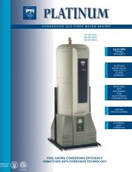
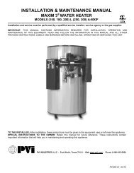
MAXIM<br />
AXIAL FLOW GAS BURNER START-UP (continued)<br />
This section pertains to MEC120 control only.<br />
When the blower motor starts, the air proving<br />
light on the MEC120 should be on. This<br />
indicates a positive airflow condition. If the air<br />
proving light is not on, turn air proving switch<br />
adjustment screw counter-clockwise until the<br />
air proving light <strong>com</strong>es on, then turn screw one<br />
turn counter-clockwise. If the gas valves open<br />
and close intermittently during normal<br />
operation, turn screw one half turn counterclockwise<br />
until this condition ceases. This<br />
procedure should be followed with every<br />
burner.<br />
After purging is <strong>com</strong>plete, terminal 3 energizes<br />
the pilot valve and terminal 4 energizes the<br />
ignition transformer on the control. The pilot is<br />
then established. The VDC reading on the<br />
meter should read a steady 14-17 VDC. Each<br />
different control will have the required flame<br />
response signal stamped on it. This is the<br />
minimum for it to properly operate. If the pilot<br />
fails to light during the initial period, it is<br />
probably due to air in the line. The control will<br />
lock out. Wait one minute and push the flame<br />
safeguard reset button to restart burner and<br />
begin the purge cycle again.<br />
Once the flame is established, set the pilot<br />
pressure (measured downstream of gas valve)<br />
at pressure shown on the tag attached to gas<br />
train. Next, open the main gas valve slowly.<br />
Set manifold pressure at pressure shown on<br />
the tag attached to gas train. Do not screw the<br />
adjusting nut of the regulator in past the point<br />
where no further increase in manifold pressure<br />
is noted. Check the in<strong>com</strong>ing pressure with the<br />
burner running. This is recorded as inlet flow<br />
pressure.<br />
Our standard flow pressure requirement on<br />
these burners is 8" W.C. flow. If the required<br />
manifold cannot be reached, check the inlet<br />
pressure. It should be a minimum of that<br />
shown on the heater decal with the burner<br />
running on full input. It is important that the<br />
in<strong>com</strong>ing pressure does not fall below these<br />
minimums or nuisance control lockouts could<br />
occur.<br />
IMPORTANT<br />
Where low gas pressure is a problem, special<br />
arrangements may have been made to fire the<br />
burner with reduced pressure. The appliance<br />
data decal will reflect this information.<br />
17. Direct Spark Ignition - (DSI) Burners - No<br />
pilot. (See wiring diagram.)<br />
Connect manometer to the manifold test port.<br />
Set the air shutter as shown on the tag<br />
attached to gas train. This may not be the<br />
exact setting you end up with, but it is a good<br />
starting point.<br />
Turn the unit on, using the rocker switch on the<br />
side of the control enclosure assembly. The<br />
burner should <strong>com</strong>e on and ignition occur. If<br />
the burner fails to ignite, there may have been<br />
air in the line. To reset the control, turn the<br />
switch off for 60 seconds (S89 controls only)<br />
and it should automatically reset, or push the<br />
reset button on the control. If after the<br />
appropriate prepurge, ignition does not occur,<br />
turn air proving switch adjustment screw<br />
counter-clockwise until TFI (try for ignition)<br />
occurs. Now in order to more precisely adjust<br />
the air failure set point, slowly turn screw<br />
clockwise until the burner shuts off. Then turn<br />
screw counter-clockwise one turn. If the gas<br />
valves open and close intermittently during<br />
normal operation, turn screw one half turn<br />
counter-clockwise until this condition ceases.<br />
Once the burner fires, set manifold pressure at<br />
pressure shown on the tag attached to gas<br />
train. There will be a tap on the downstream<br />
side of the valve to measure pressure. The<br />
manifold pressure must be taken downstream<br />
of the gas valve. Check the in<strong>com</strong>ing pressure<br />
with the burner running. This recorded flow<br />
pressure must be the minimum specified on<br />
the heater decal.<br />
PV500-17 07/13 11<br />
Section 17