Design of two-span trapezoidal roof sheeting - Steel-stainless.org
Design of two-span trapezoidal roof sheeting - Steel-stainless.org
Design of two-span trapezoidal roof sheeting - Steel-stainless.org

You also want an ePaper? Increase the reach of your titles
YUMPU automatically turns print PDFs into web optimized ePapers that Google loves.
Job No. Sheet 1 <strong>of</strong> 6 Rev A<br />
CALCULATION SHEET<br />
Job Title<br />
Subject<br />
Client<br />
RFCS Stainless <strong>Steel</strong> Valorisation Project<br />
<strong>Design</strong> Example 11 – <strong>Design</strong> <strong>of</strong> a <strong>two</strong>-<strong>span</strong> <strong>trapezoidal</strong><br />
ro<strong>of</strong> <strong>sheeting</strong><br />
Made by JG/AO Date Feb 2006<br />
RFCS<br />
Checked by GZ Date March 2006<br />
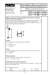
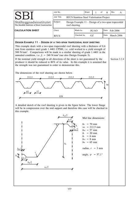
DESIGN EXAMPLE 11 – DESIGN OF A TWO-SPAN TRAPEZOIDAL ROOF SHEETING<br />
This example deals with a <strong>two</strong>-<strong>span</strong> <strong>trapezoidal</strong> ro<strong>of</strong> <strong>sheeting</strong> with a thickness <strong>of</strong> 0,6<br />
mm from <strong>stainless</strong> steel grade 1.4401 CP500, i.e. cold worked to a yield strength <strong>of</strong><br />
500 N/mm 2 . Comparisons will be made to a similar <strong>sheeting</strong> <strong>of</strong> grade 1.4401 in the<br />
annealed condition, i.e. fy = 240 N/mm 2 (see also <strong>Design</strong> Example 3).<br />
If the nominal yield strength in all directions <strong>of</strong> the sheet is not guaranteed by the<br />
producer it should be reduced to 80% <strong>of</strong> its value. In this example it is assumed that<br />
the strength was not guaranteed in order to demonstrate this.<br />
Section 3.2.4<br />
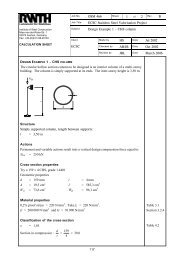
The dimensions <strong>of</strong> the ro<strong>of</strong> <strong>sheeting</strong> are shown below.<br />
212,5 212,5 212,5 212,5<br />
70<br />
65 57<br />
850<br />
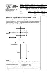
A detailed sketch <strong>of</strong> the ro<strong>of</strong> <strong>sheeting</strong> is given in the figure below. The lower flange<br />
will be in compression over the mid support and therefore this case will be checked in<br />
this example.<br />
b u0 /2<br />
h 0<br />
b r /2<br />
h r<br />
b r0 /2<br />
Mid line dimensions:<br />
h0 = 70 mm<br />
w0 = 212,5 mm<br />
bu0 = 57 mm<br />
br = 20 mm<br />
hr = 6 mm<br />
br0 = 8 mm<br />
bl0 = 65 mm<br />
h r<br />
b r0 /2<br />
b r /2<br />
r<br />
radius, r = 3 mm<br />
angle, ϕ = 57,1°<br />
b l0 /2<br />
w 0 /2<br />
177
Job No. Sheet 2 <strong>of</strong> 6 Rev A<br />
CALCULATION SHEET<br />
Job Title<br />
Subject<br />
Client<br />
RFCS Stainless <strong>Steel</strong> Valorisation Project<br />
<strong>Design</strong> Example 11 – <strong>Design</strong> <strong>of</strong> a <strong>two</strong>-<strong>span</strong> <strong>trapezoidal</strong><br />
ro<strong>of</strong> <strong>sheeting</strong><br />
Made by JG/AO Date Feb 2006<br />
RFCS<br />
Checked by GZ Date March 2006<br />
Data<br />
Span length<br />
L = 3,5 m<br />
Load q = 1,4 kN/m 2<br />
Self weight g = 0,07 kN/m 2<br />
Sheeting thickness<br />
t = 0,6 mm<br />
Width <strong>of</strong> support<br />
ss = 100 mm<br />
Yield strength fy = 0 ,8× 500 = 400 N/mm 2<br />
Modulus <strong>of</strong> elasticity E = 200 000 N/mm 2<br />
Partial factor γM0 = 1,1<br />
Partial factor γM1 = 1,1<br />
Load factor<br />
γG = 1,35 (permanent loads)<br />
Load factor γQ = 1,5 (variable loads)<br />
Table 3.5<br />
Table 2.1<br />
Table 2.1<br />
Section 2.3.2<br />
Section 2.3.2<br />
Effective section properties<br />
Maximum width-to-thickness ratios<br />
Table 4.1<br />
max( bl0 / t, bu0 / t) = bl0<br />
/ t = 108 < 400<br />
h / t = 117 < 400<br />
0<br />
Location <strong>of</strong> the centroidal axis when the web is fully effective<br />
Effective width <strong>of</strong> the compression flange Section 4.4.1<br />
bl0<br />
− br<br />
235 E<br />
bp<br />
= = 22,5 mm ε = = 0,75<br />
Table 4.2<br />
2<br />
fy<br />
210000<br />
bp<br />
/ t<br />
Table 4.3<br />
k<br />
σ<br />
= 4<br />
λp<br />
= = 0,883<br />
Eq. 4.2<br />
28, 4ε<br />
kσ<br />
0,772 0,125<br />
ρ = 0,714<br />
2<br />
λ<br />
− λ<br />
= b = ρb<br />
= 16,1 mm<br />
Eq. 4.1a<br />
eff,l p Table 4.3<br />
p<br />
p<br />
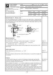
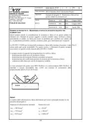
Reduced thickness <strong>of</strong> the flange stiffener: Section 4.5.3<br />
The lower compressed flange is shown in detail below.<br />
b p b eff,l /2<br />
t sl<br />
Intermediate stiffener<br />
e s<br />
A s , I s<br />
b s<br />
178
Job No. Sheet 3 <strong>of</strong> 6 Rev A<br />
CALCULATION SHEET<br />
Job Title<br />
Subject<br />
Client<br />
RFCS Stainless <strong>Steel</strong> Valorisation Project<br />
<strong>Design</strong> Example 11 – <strong>Design</strong> <strong>of</strong> a <strong>two</strong>-<strong>span</strong> <strong>trapezoidal</strong><br />
ro<strong>of</strong> <strong>sheeting</strong><br />
Made by JG/AO Date Feb 2006<br />
Effective thickness <strong>of</strong> the inclined part <strong>of</strong> the stiffener<br />
⎛<br />
2<br />
br<br />
b<br />
⎞<br />
r0 2<br />
⎜<br />
⎛ − ⎞<br />
+ h ⎟<br />
r<br />
t<br />
⎜<br />
⎜<br />
2<br />
⎟<br />
⎝ ⎠ ⎟<br />
trl<br />
=<br />
⎝<br />
⎠<br />
= 0,85 mm<br />
h<br />
A b b t ht<br />
r<br />
RFCS<br />
Checked by GZ Date March 2006<br />
2<br />
s<br />
= (<br />
eff,l<br />
+<br />
r0) + 2<br />
r rl<br />
= 24,62 mm<br />
Figure 4.3<br />
hr<br />
bht<br />
r0 r<br />
+ 2hr trl<br />
e<br />
2<br />
s<br />
= = 2, 41 mm<br />
A<br />
s<br />
The second moment <strong>of</strong> area for the stiffener is calculated with <strong>two</strong> strips <strong>of</strong> width 15t<br />
adjacent to the stiffener (smaller terms neglected)<br />
2 3<br />
2 2 2 ⎛hr ⎞ trlhr<br />
4<br />
Is = 2× 15 t es + br0t( hr − es) + 2ht r rl⎜<br />
− es⎟<br />
+ 2 = 159,1 mm<br />
⎝ 2 ⎠ 12<br />
2<br />
2 ⎛br − br0<br />
⎞<br />
s r r0<br />
b = 2 h + ⎜ + b = 24,97 mm<br />
2<br />
⎟<br />
⎝ ⎠<br />
2<br />
4 s p p s<br />
b 3<br />
l<br />
s<br />
Figure 4.3<br />
Ib (2b + 3 b)<br />
= 3,07 = 251,0 mm<br />
Eq. 4.9<br />
t<br />
2<br />
⎛w0 −bu0 −bl0<br />
⎞ 2<br />
w<br />
= + h0 = 83,4 mm<br />
⎜<br />
⎝<br />
d p s<br />
2<br />
⎟<br />
⎠<br />
b = 2b + b = 70,0 mm<br />
Eq. 4.11<br />
k<br />
s<br />
+ 2b<br />
w d<br />
wo<br />
= =<br />
sw<br />
+ 0,5bd<br />
1, 37<br />
Eq. 4.10<br />
lb s<br />
w<br />
= 3, 01> 2 kw = kwo = 1,37 Eq. 4.7<br />
4, 2k E I t<br />
σ = = 557,5 N/mm<br />
4 (2 3 )<br />
λ<br />
3<br />
w<br />
s<br />
cr,s 2<br />
As bp bp + bs<br />
f<br />
y<br />
d<br />
= = 0,85 <br />
d d<br />
σ<br />
cr,s<br />
2<br />
Eq. 4.3<br />
χ = 1, 47 − 0, 723λ<br />
= 0,86<br />
Eq. 4.16<br />
tred = χdt<br />
= 0,51 mm<br />
Optionally iterate to refine the value <strong>of</strong> the reduction factor for buckling <strong>of</strong> the<br />
stiffener.<br />
prEN 1993-<br />
1-3, clause<br />
5.5.3.3 (3)<br />
179
Job No. Sheet 4 <strong>of</strong> 6 Rev A<br />
CALCULATION SHEET<br />
Job Title<br />
Subject<br />
Client<br />
RFCS Stainless <strong>Steel</strong> Valorisation Project<br />
<strong>Design</strong> Example 11 – <strong>Design</strong> <strong>of</strong> a <strong>two</strong>-<strong>span</strong> <strong>trapezoidal</strong><br />
ro<strong>of</strong> <strong>sheeting</strong><br />
Made by JG/AO Date Feb 2006<br />
RFCS<br />
Checked by GZ Date March 2006<br />
Distance to the neutral axis from the compressed flange (fully effective web)<br />
2<br />
A = A i<br />
= 84,0 mm<br />
e<br />
c<br />
tot<br />
∑<br />
∑<br />
Ae<br />
i i<br />
= = 36,3 mm<br />
A<br />
tot<br />
Effective cross-section <strong>of</strong> the web Section 4.4.1<br />
h0 − ec<br />
2<br />
ψ =− =− 0,929<br />
k σ<br />
= 7,81− 6,29ψ + 9,78ψ<br />
= 22,1<br />
e<br />
Table 4.3<br />
c<br />
bp,w = sw = 83,4 mm<br />
0,772 0,125<br />
ρ = 0, 490<br />
λ<br />
− λ<br />
= <br />
s<br />
p<br />
2<br />
p<br />
λ<br />
b<br />
/ t<br />
p,w<br />
p<br />
= = 1,391<br />
Eq. 4.2<br />
28,4ε<br />
kσ<br />
b<br />
b<br />
1−ψ<br />
p,w<br />
eff,w<br />
= ρ =<br />
eff,1<br />
= 0, 4beff,w<br />
= 8, 47 mm seff,2 beff,w<br />
21,2 mm<br />
Eq. 4.1a,<br />
Table 4.3<br />
= 0,6 = 12,7 mm<br />
Table 4.3<br />
Effective cross section properties per half corrugation<br />
∑<br />
∑<br />
Aeff,tot = Aeff, i<br />
= 70,8 mm<br />
e<br />
A<br />
e<br />
eff, i eff, i<br />
eff,c<br />
= =<br />
Aeff,tot<br />
∑ ∑<br />
2<br />
40,0 mm<br />
( ) 2 4<br />
Itot = Ieff,i + Aeff,i ec − eeff,i = 51710 mm<br />
Bending resistance per unit width (1m) Section 4.7.4<br />
1000 mm<br />
I = Itot<br />
= 486685 mm<br />
0,5w<br />
W<br />
eff,l<br />
I<br />
= = 12165 mm<br />
e<br />
c<br />
0<br />
3<br />
4<br />
W<br />
eff,u<br />
= I<br />
16227 mm<br />
h − e<br />
=<br />
0 c<br />
3<br />
Weff,l < Weff,u Weff,min = Weff,l<br />
Mc,Rd = Weff,min fy γ<br />
M0<br />
= 4, 42 kNm<br />
Eq. 4.29<br />
180
Job No. Sheet 5 <strong>of</strong> 6 Rev A<br />
CALCULATION SHEET<br />
Job Title<br />
Subject<br />
Client<br />
RFCS Stainless <strong>Steel</strong> Valorisation Project<br />
<strong>Design</strong> Example 11 – <strong>Design</strong> <strong>of</strong> a <strong>two</strong>-<strong>span</strong> <strong>trapezoidal</strong><br />
ro<strong>of</strong> <strong>sheeting</strong><br />
Made by JG/AO Date Feb 2006<br />
RFCS<br />
Checked by GZ Date March 2006<br />
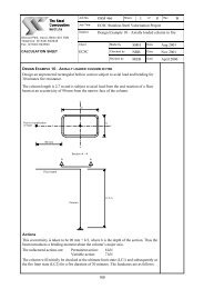
Resistance to local transverse forces at intermediate support<br />
Resistance to local transverse forces per unit width (1 m)<br />
α = 0,15 (for <strong>sheeting</strong> pr<strong>of</strong>iles) and la = ss<br />
1000 mm<br />
R = αt f E − r t + l t + ϕ γ<br />
2<br />
( 1 0,1 / ) ⎡0,5 0,02 / ⎤( 2,4 ( /90)<br />
)<br />
2<br />
w,Rd y ⎣<br />
a ⎦<br />
M1<br />
0,5w0<br />
Rw,Rd = 20,9 kN<br />
prEN 1993-<br />
1-3, Eq.<br />
6.20c, 6.19b<br />
and 6.18<br />
Interaction between bending moment and transverse force<br />
The maximum bending moment will appear at the intermediate support where it will<br />
interact with the support reaction and therefore the following checks must be<br />
performed.<br />
M<br />
Ed<br />
1<br />
M ≤ FEd<br />
MEd<br />
FEd<br />
≤ 1<br />
+ ≤ 1, 25<br />
R<br />
M R<br />
c,Rd<br />
w,Rd<br />
c,Rd<br />
w,Rd<br />
prEN 1993-<br />
1-3, Eqs.<br />
6.28a-c<br />
<strong>Design</strong> load per unit width (1 m) Section 2.3.2<br />
qd = γ<br />
Gg+ γ<br />
Qq= 2,20 kN/m<br />
Eq. 2.3<br />
The design load, qd, gives the following bending moment and support reaction at the<br />
intermediate support.<br />
2<br />
qL<br />
5<br />
M<br />
Ed<br />
= = 3,37 kNm FEd<br />
= qL=<br />
9,63 kN<br />
8<br />
4<br />
M<br />
Ed<br />
0,76<br />
M = FEd<br />
MEd<br />
FEd<br />
= 0, 46<br />
+<br />
R<br />
M R<br />
= 1, 22 OK<br />
c,Rd<br />
w,Rd<br />
c,Rd<br />
w,Rd<br />
Deflection at serviceability limit state<br />
For verification in the serviceability limit state the effective width <strong>of</strong> compression<br />
elements should be based on the compressive stress in the element under serviceability<br />
limit state loading. The maximum compression stress is calculated as follows. A<br />
conservative approximation is made based on Weff,min from ultimate limit state.<br />
( q+<br />
g) L<br />
2<br />
prEN 1993-<br />
1-3, clause<br />
5.5.1(4)<br />
M<br />
Ed,ser<br />
= = 2, 25 kNm<br />
Section 2.3.4<br />
8<br />
M<br />
Ed,ser 2<br />
σ<br />
com,Ed,ser<br />
= = 186 N/mm<br />
W<br />
eff,min<br />
Now, the effective section properties are determined as before but with fy replaced by<br />
σcom,Ed,ser. The calculations will not be shown here but the interesting results are:<br />
I = 573 150 mm 4<br />
Wu = 15 866 mm 3<br />
Wl = 16 919 mm 3<br />
181
Job No. Sheet 6 <strong>of</strong> 6 Rev A<br />
CALCULATION SHEET<br />
Job Title<br />
Subject<br />
Client<br />
RFCS Stainless <strong>Steel</strong> Valorisation Project<br />
<strong>Design</strong> Example 11 – <strong>Design</strong> <strong>of</strong> a <strong>two</strong>-<strong>span</strong> <strong>trapezoidal</strong><br />
ro<strong>of</strong> <strong>sheeting</strong><br />
Made by JG/AO Date Feb 2006<br />
RFCS<br />
Checked by GZ Date March 2006<br />
Determination <strong>of</strong> the deflection:<br />
Secant modulus corresponding to the stresses in the tension and compression flange<br />
respectively.<br />
M<br />
Ed,ser 2<br />
σ<br />
1,Ed,ser<br />
= = 142 N/mm<br />
W<br />
u<br />
M<br />
σ<br />
2,Ed,ser<br />
= = 133 N/mm<br />
W<br />
E<br />
E<br />
Ed,ser 2<br />
l<br />
E<br />
= = 199 604 N/mm<br />
s,1 n−1<br />
E ⎛σ<br />
⎞<br />
1,Ed,ser<br />
1+ 0,002<br />
f ⎜<br />
y<br />
f ⎟<br />
⎝ y ⎠<br />
E<br />
= = 199 730 N/mm<br />
n−<br />
E ⎛σ<br />
⎞<br />
2,Ed,ser<br />
1+ 0,002<br />
f ⎜<br />
y<br />
f ⎟<br />
⎝ y ⎠<br />
s,2 1<br />
Es,1 + Es,2 2<br />
Es<br />
= = 199 667 N/mm<br />
2<br />
2<br />
2<br />
n = 7,0<br />
As a simplification, the variation <strong>of</strong> Es along the length <strong>of</strong> the member may be<br />
neglected and the minimum value <strong>of</strong> Es <strong>of</strong> that member may conservatively be used<br />
throughout its length, i.e.<br />
Es = Es,1 = 199 603 N/mm 2<br />
The permitted deflection is L/300 = 11,7 mm<br />
1+<br />
33<br />
x= L= 1, 47 m (location <strong>of</strong> maximum deflection)<br />
16<br />
( ) 4 3 4<br />
g+ q L ⎛ x x x ⎞<br />
δ = ⎜ − 3 + 2 10,4 mm<br />
3 4 ⎟=<br />
48Es,1I ⎝L L L ⎠<br />
OK<br />
Appendix C<br />
Appendix C<br />
Table C.1<br />
Appendix C<br />
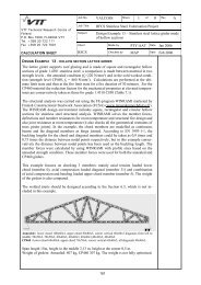
Comparison with <strong>sheeting</strong> in grade 1.4401 in the annealed condition<br />
The bending resistance per unit width <strong>of</strong> identical <strong>sheeting</strong> in grade 1.4401 in the<br />
annealed condition (fy = 240 N/mm 2 ) is:<br />
Mc,Rd = 3,22 kNm<br />
and the resistance to local transverse forces is:<br />
Rw,Rd = 16,2 kN<br />
With <strong>sheeting</strong> made from grade 1.4401 in the annealed condition, the <strong>span</strong> must be<br />
reduced to 2,9 m compared to 3,5 m for material in the cold worked strength<br />
condition. Hence, <strong>sheeting</strong> made from cold worked material enables the <strong>span</strong> to be<br />
increased, meaning that the number <strong>of</strong> secondary beams or purlins could be reduced,<br />
leading to cost reductions.<br />
182