GM Testing - Snap-on
GM Testing - Snap-on
GM Testing - Snap-on

Create successful ePaper yourself
Turn your PDF publications into a flip-book with our unique Google optimized e-Paper software.
Chapter 8<br />
<str<strong>on</strong>g>GM</str<strong>on</strong>g> <str<strong>on</strong>g>Testing</str<strong>on</strong>g><br />
This chapter provides informati<strong>on</strong> and procedures for using the scan tool with the following<br />
c<strong>on</strong>trol systems:<br />
• Engine<br />
• Transmissi<strong>on</strong><br />
• Airbag<br />
• Antilock Brake System (ABS)<br />
For additi<strong>on</strong>al informati<strong>on</strong> <strong>on</strong> <str<strong>on</strong>g>GM</str<strong>on</strong>g> vehicles, see the following secti<strong>on</strong>s:<br />
• “<str<strong>on</strong>g>GM</str<strong>on</strong>g> Operati<strong>on</strong>s” <strong>on</strong> page 121<br />
• “<str<strong>on</strong>g>GM</str<strong>on</strong>g> Data Parameters” <strong>on</strong> page 435<br />
• “<str<strong>on</strong>g>GM</str<strong>on</strong>g> Communicati<strong>on</strong>s Problems” <strong>on</strong> page 731<br />
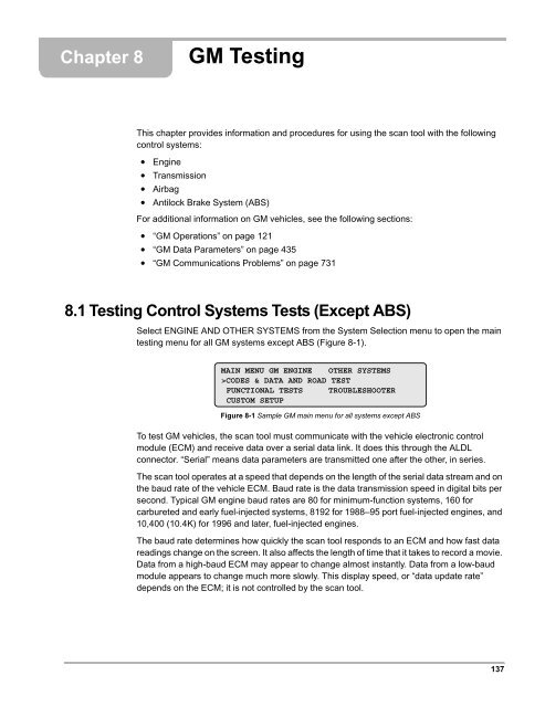
8.1 <str<strong>on</strong>g>Testing</str<strong>on</strong>g> C<strong>on</strong>trol Systems Tests (Except ABS)<br />
Select ENGINE AND OTHER SYSTEMS from the System Selecti<strong>on</strong> menu to open the main<br />
testing menu for all <str<strong>on</strong>g>GM</str<strong>on</strong>g> systems except ABS (Figure 8-1).<br />
MAIN MENU <str<strong>on</strong>g>GM</str<strong>on</strong>g> ENGINE OTHER SYSTEMS<br />
>CODES & DATA AND ROAD TEST<br />
FUNCTIONAL TESTS TROUBLESHOOTER<br />
CUSTOM SETUP<br />
Figure 8-1 Sample <str<strong>on</strong>g>GM</str<strong>on</strong>g> main menu for all systems except ABS<br />
To test <str<strong>on</strong>g>GM</str<strong>on</strong>g> vehicles, the scan tool must communicate with the vehicle electr<strong>on</strong>ic c<strong>on</strong>trol<br />
module (ECM) and receive data over a serial data link. It does this through the ALDL<br />
c<strong>on</strong>nector. “Serial” means data parameters are transmitted <strong>on</strong>e after the other, in series.<br />
The scan tool operates at a speed that depends <strong>on</strong> the length of the serial data stream and <strong>on</strong><br />
the baud rate of the vehicle ECM. Baud rate is the data transmissi<strong>on</strong> speed in digital bits per<br />
sec<strong>on</strong>d. Typical <str<strong>on</strong>g>GM</str<strong>on</strong>g> engine baud rates are 80 for minimum-functi<strong>on</strong> systems, 160 for<br />
carbureted and early fuel-injected systems, 8192 for 1988–95 port fuel-injected engines, and<br />
10,400 (10.4K) for 1996 and later, fuel-injected engines.<br />
The baud rate determines how quickly the scan tool resp<strong>on</strong>ds to an ECM and how fast data<br />
readings change <strong>on</strong> the screen. It also affects the length of time that it takes to record a movie.<br />
Data from a high-baud ECM may appear to change almost instantly. Data from a low-baud<br />
module appears to change much more slowly. This display speed, or “data update rate”<br />
depends <strong>on</strong> the ECM; it is not c<strong>on</strong>trolled by the scan tool.<br />
137
Chapter 8 <str<strong>on</strong>g>GM</str<strong>on</strong>g><br />
<str<strong>on</strong>g>Testing</str<strong>on</strong>g> C<strong>on</strong>trol Systems Tests (Except ABS)<br />
8.1.1 Bidirecti<strong>on</strong>al Modules<br />
Many late-model <str<strong>on</strong>g>GM</str<strong>on</strong>g> vehicles have bidirecti<strong>on</strong>al ECMs. This means that the ECM not <strong>on</strong>ly<br />
transmits data, but also accepts commands from the scan tool. Bidirecti<strong>on</strong>al ECMs transmit a<br />
complete data stream to the scan tool and provide many functi<strong>on</strong>al test capabilities.<br />
The scan tool provides many of these bidirecti<strong>on</strong>al capabilities <strong>on</strong> late-model <str<strong>on</strong>g>GM</str<strong>on</strong>g> vehicles<br />
However, a few special test commands that override normal c<strong>on</strong>trol module operati<strong>on</strong> are<br />
restricted to <str<strong>on</strong>g>GM</str<strong>on</strong>g> test equipment. See “<str<strong>on</strong>g>GM</str<strong>on</strong>g> Communicati<strong>on</strong>s Problems” <strong>on</strong> page 731 if the<br />
scan tool cannot communicate with the vehicle.<br />
8.1.2 Scan Tool Communicati<strong>on</strong><br />
The CODES & DATA and FUNCTIONAL TESTS selecti<strong>on</strong>s <strong>on</strong> the main menus require the<br />
scan tool to communicate with the selected ECM. The igniti<strong>on</strong> must be <strong>on</strong> to establish<br />
communicati<strong>on</strong>. Select either CODES & DATA or FUNCTIONAL TESTS and a “waiting for<br />
module to communicate” message displays (Figure 8-2).<br />
WAITING FOR MODULE TO COMMUNICATE WITH<br />
SCANNER. CONNECT ALDL CONNECTOR.<br />
TURN KEY ON.<br />
Figure 8-2 Sample waiting for module to communicate message<br />
If communicati<strong>on</strong> is not established within five sec<strong>on</strong>ds, the screen updates to display a “no<br />
communicati<strong>on</strong>” message (Figure 8-3).<br />
NO COMMUNICATION. IS KEY ON? IS ALDL<br />
CONNECTED? WAIT 15 SECONDS. PRESS N TO<br />
REENTER VEHICLE IDENTIFICATION, OR<br />
SEE REFERENCE MANUAL “APPENDIX B”.<br />
Figure 8-3 Sample no communicati<strong>on</strong> message<br />
This message stays <strong>on</strong> the screen until communicati<strong>on</strong> is established, then the scan tool<br />
displays the selected functi<strong>on</strong>.<br />
If communicati<strong>on</strong> is established, but it does not match what the scan tool is looking for, a<br />
“communicati<strong>on</strong> mismatch” message displays (Figure 8-4).<br />
COMMUNICATION MISMATCH.<br />
PRESS N TO REENTER VEHICLE ID.<br />
OR PRESS Y TO CONTINUE.<br />
Figure 8-4 Sample communicati<strong>on</strong> mismatch message<br />
This generally occurs if the vehicle is improperly identified or if the selected module has the<br />
wr<strong>on</strong>g PROM installed. It may also be due to undocumented midyear changes.<br />
138
8.1.3 Codes & Data Selecti<strong>on</strong>s<br />
The Codes & Data selecti<strong>on</strong>s for different vehicles vary, but each <strong>on</strong>e, with or without road<br />
test, opens a data display screen that presents DTCs and <strong>on</strong>board computer data. The Codes<br />
& Data test selecti<strong>on</strong>s are:<br />
• CODES & DATA—displays trouble codes and data stream informati<strong>on</strong> from the selected<br />
ECM. The vehicle should not be driven during this test.<br />
• ROAD TEST (C & D)—allows the vehicle to be driven while displaying trouble codes and<br />
data stream informati<strong>on</strong> from the selected ECM.<br />
• ROAD TEST (No C & D)—allows the vehicle to be driven with the scan tool c<strong>on</strong>nected,<br />
but no trouble codes or data display while driving.<br />
• CODES & DATA AND ROAD TEST—displays trouble codes and data stream<br />
informati<strong>on</strong> from the selected ECM, whether or not the vehicle is being driven.<br />
• CODES—displays trouble codes <strong>on</strong>ly, no data parameters.<br />
• CODES & DATA MENU—accesses a submenu of data test selecti<strong>on</strong>s that group similar<br />
data parameters together <strong>on</strong> smaller data lists for faster, more efficient testing.<br />
• CODE HISTORY—displays code history informati<strong>on</strong>.<br />
• ADAPTIVE REPORT—displays the adaptive, or learned, informati<strong>on</strong> that the<br />
transmissi<strong>on</strong> c<strong>on</strong>trol module (TCM) uses to c<strong>on</strong>trol shifting.<br />
Codes & Data<br />
Selecting CODES & DATA displays the data list and trouble codes for the selected module.<br />
Data for carbureted engines is slightly different than for fuel-injected engines, but both work<br />
the same (Figure 8-5 and Figure 8-6).<br />
RPM__1234 O2(mV)__689 MC DWL(°)__38<br />
** DIAGNOSTIC MODE. DO NOT DRIVE. **<br />
NO CODES PRESENT<br />
O2 CROSSCOUNTS___08 OPEN/CLSD LOOP_OPEN<br />
Figure 8-5 Sample <str<strong>on</strong>g>GM</str<strong>on</strong>g> Codes & Data display for a carbureted engine<br />
RPM__1234 O2(mV)__689 INTEGRATR__128<br />
** DIAGNOSTIC MODE. DO NOT DRIVE. **<br />
NO CODES PRESENT<br />
O2 SENSOR B1______05 O2 SENSOR B2_____06<br />
Figure 8-6 Sample <str<strong>on</strong>g>GM</str<strong>on</strong>g> Codes & Data display for a fuel-injected engine<br />
Data Lists<br />
Some <str<strong>on</strong>g>GM</str<strong>on</strong>g> vehicles transmit slightly different data lists for different test functi<strong>on</strong>s. For example,<br />
certain models transmit a data list during some functi<strong>on</strong>al tests that is shorter than the data list<br />
transmitted in diagnostic mode. Some models do not transmit codes during a road test.<br />
However, many <str<strong>on</strong>g>GM</str<strong>on</strong>g> vehicles transmit the same data under all c<strong>on</strong>diti<strong>on</strong>s.<br />
139
Chapter 8 <str<strong>on</strong>g>GM</str<strong>on</strong>g><br />
<str<strong>on</strong>g>Testing</str<strong>on</strong>g> C<strong>on</strong>trol Systems Tests (Except ABS)<br />
On OBD-II vehicles, the scan tool displays the data parameters in as many as five separate<br />
data lists. Whether a vehicle transmits an identical data list or variable data lists for different<br />
test c<strong>on</strong>diti<strong>on</strong>s affects some settings <strong>on</strong> the scan tool.<br />
• Fix display lines or reassign LED functi<strong>on</strong>s for an ECM that always transmits the same<br />
data list and those settings stay in the scan tool memory until they are changed or a new<br />
vehicle ID is entered.<br />
• Fix display lines or reassign LED functi<strong>on</strong>s for a vehicle that transmits variable data lists<br />
and those settings return to their preassigned functi<strong>on</strong>s when test selecti<strong>on</strong>s are changed<br />
(when changing from Road Test to Diagnostic <str<strong>on</strong>g>Testing</str<strong>on</strong>g> mode, for example).<br />
See the user’s manual for the diagnostic tool you are using for instructi<strong>on</strong>s <strong>on</strong> reassigning<br />
LED functi<strong>on</strong>s.<br />
Diagnostic Trouble Codes<br />
On some vehicles, diagnostic trouble code (DTC) informati<strong>on</strong> appears as part of the data list<br />
(Figure 8-7).<br />
RPM__1234 O2(mV)__689 INTEGRATR__128<br />
** ROAD TEST MODE. OK TO DRIVE. **<br />
13 O2 SENSOR NOT WARM ENOUGH<br />
15 COOLANT TEMP SIGNAL HIGH OR OPEN<br />
Figure 8-7 Sample codes present screen<br />
Most body c<strong>on</strong>trol module (BCM) trouble codes include an alpha prefix. These BCM codes<br />
display alphanumerically.<br />
Hard Codes and Soft Codes<br />
On some 1995 and earlier models, DTCs may be classified as either “hard” or “soft.” Most<br />
1988 and later <str<strong>on</strong>g>GM</str<strong>on</strong>g> vehicle c<strong>on</strong>trollers separate soft codes from hard codes.<br />
• Hard codes—indicate a problem that exists at the time of testing. These are referred to<br />
as “current codes” in the trouble code menu.<br />
• Soft codes—indicate a problem that occurred in the past but is not present now. These<br />
are referred to as “history codes” in the trouble code menu.<br />
z To distinguish between hard and soft codes:<br />
1. Clear the ECM memory and reenter Codes & Data.<br />
2. Watch for codes to reappear:<br />
– A hard code reappears quickly—from immediately to a couple of minutes.<br />
– A soft code does not reappear until the problem that caused it reoccurs.<br />
1995 and Earlier Cadillac Engine System Codes<br />
Cadillac systems transmit hard codes for the engine. However, soft codes are available <strong>on</strong>ly<br />
from the Cadillac <strong>on</strong>-board diagnostic system, with the following excepti<strong>on</strong>s:<br />
140
• 1989 and earlier models transmit a soft code 52<br />
• 1990–95 models transmit soft codes 52 and 109<br />
Refer to Cadillac service procedures or the Fast-Track Troubleshooter Reference G074 for<br />
instructi<strong>on</strong>s <strong>on</strong> using the Cadillac system.<br />
Diagnostic Trouble Codes Without Definiti<strong>on</strong>s<br />
Some OBD-II <str<strong>on</strong>g>GM</str<strong>on</strong>g> vehicles output OBD-II style DTCs that have varying definiti<strong>on</strong>s. The correct<br />
DTC definiti<strong>on</strong> cannot be determined by the VIN characters entered during the vehicle ID<br />
sequence. In these instances, the display shows the DTC followed by a message that refers<br />
you to this manual. Use Table 8-1 and Table 8-2 to determine the DTC definiti<strong>on</strong>.<br />
Table 8-1 2001 and earlier passenger car DTCs with multiple definiti<strong>on</strong>s (sheet 1 of 2)<br />
DTCs with Multiple Definiti<strong>on</strong>s–Cars<br />
DTC YEAR 4th VIN ENGINE DEFINITION<br />
1996 B/D/Y 4.3/5.7<br />
1996–97 F 5.7<br />
Fan relay #1 circuit fault<br />
1996–99 Z 1.9 QDM “A” fault<br />
P1641 1996–2001 All others MIL c<strong>on</strong>trol circuit<br />
1998 W 3.8<br />
1999<br />
All 3.8 A/C relay<br />
N 3.4<br />
A,L,N,W 3.1/3.4 Air pump relay circuit<br />
1996 All others<br />
Cooling fan relay 2 c<strong>on</strong>trol circuit<br />
Y 5.7<br />
1996–97 F 5.7<br />
Cooling fan relay 2 & 3 c<strong>on</strong>trol circuit<br />
P1642<br />
E/K 4.6<br />
1996–99<br />
G, Olds <strong>on</strong>ly 4.0<br />
Vehicle speed output circuit<br />
1997–98 All others Driver 1 line 2<br />
1998–99 W 3.1<br />
1999 N 3.4<br />
Change oil lamp circuit<br />
1996 B/D/Y 4.3/5.7<br />
P1643 1996–97 F 5.7<br />
Engine speed output circuit<br />
1996–98 All others Fuel pump PWM circuit<br />
141
Chapter 8 <str<strong>on</strong>g>GM</str<strong>on</strong>g><br />
<str<strong>on</strong>g>Testing</str<strong>on</strong>g> C<strong>on</strong>trol Systems Tests (Except ABS)<br />
Table 8-1 2001 and earlier passenger car DTCs with multiple definiti<strong>on</strong>s (sheet 2 of 2)<br />
DTCs with Multiple Definiti<strong>on</strong>s–Cars<br />
DTC YEAR 4th VIN ENGINE DEFINITION<br />
P1652<br />
P1653<br />
P1654<br />
B/D/Y 4.3/5.7 Vehicle speed output circuit<br />
1996<br />
A/L/N/W 3.1 Fan relay #2 circuit fault<br />
1996–97 F 5.7 Vehicle speed output circuit<br />
1996–98 C/F/G/H 3.8 Fan relay #2 circuit fault<br />
E/K 4.6<br />
1996–99<br />
Lift/dive output circuit<br />
G 4.0<br />
1997–2000 Y 5.7 Chassis pitch fault<br />
1999 C/H/W 3.8 Fan relay #2 circuit fault<br />
W 3.1<br />
1999<br />
Fan relay 2 & 3 circuit<br />
N 3.4<br />
1999–2001 F 3.8 Ride c<strong>on</strong>trol circuit<br />
E/K 4.6 A/C clutch c<strong>on</strong>trol circuit<br />
1996<br />
All others<br />
Low engine oil level lamp fault<br />
1996–98 C/G/H 3.8 TCS delivered torque output circuit<br />
1996–99 G 4.0 A/C clutch c<strong>on</strong>trol circuit<br />
F/W 3.1/3.8 Fuel level output fault<br />
1998 F 5.7 Low engine oil level lamp fault<br />
F 3.8 TCS delivered torque output circuit<br />
1999 All others Fuel level output or low oil level lamp circuit<br />
2000–01 All Low engine oil level lamp fault<br />
E/K 4.6<br />
1996–99<br />
Cruise c<strong>on</strong>trol disable circuit fault<br />
G 4.0<br />
1996–98 All others A/C relay circuit fault<br />
W 3.1<br />
1999<br />
2nd gear start lamp circuit<br />
N 3.4<br />
1999–2000 C/F/G/H/W 3.8 Reduced engine power lamp circuit<br />
Table 8-2 Truck DTCs with multiple definiti<strong>on</strong>s (sheet 1 of 2)<br />
DTCs with Multiple Definiti<strong>on</strong>s–Trucks<br />
DTC YEAR 5th VIN ENGINE DEFINITION<br />
P1641 2000 P 6.5 MIL c<strong>on</strong>trol circuit fault<br />
P1642 1996 U 3.4 Air pump relay<br />
P1643 1997–2001 All 6.5 Wait to start circuit<br />
P1652<br />
U 3.4 Fan relay #2 circuit fault<br />
1996<br />
Others - Vehicle speed output circuit<br />
Powertrain induced chassis pitch circuit<br />
2000 All 4.8/5.3/6.0<br />
fault<br />
142
Table 8-2 Truck DTCs with multiple definiti<strong>on</strong>s (sheet 2 of 2)<br />
DTCs with Multiple Definiti<strong>on</strong>s–Trucks<br />
DTC YEAR 5th VIN ENGINE DEFINITION<br />
1996 All 4.3/5.0/5.7/7.4 Oil level lamp fault<br />
P1653 1996–97 All 6.5 EGR vent solenoid circuit fault<br />
1999–2000 All 6.5/7.4 EGR vent sol or EPR circuit<br />
P1654 1996–2001 All 6.5/7.4 Service throttle so<strong>on</strong> circuit<br />
Road Test (C&D)<br />
Selecting ROAD TEST (C&D) from the MAIN MENU <str<strong>on</strong>g>GM</str<strong>on</strong>g> ENGINE initiates what some service<br />
manuals may call the “open” or “normal” mode because the scan tool does not place a load<br />
across the ALDL c<strong>on</strong>nector as it does in the diagnostic mode (Figure 8-8).<br />
RPM__1234 O2(mV)__689 INTEGRATR__128<br />
** ROAD TEST MODE. OK TO DRIVE. **<br />
NO CODES PRESENT<br />
O2 SENSOR B1______05 O2 SENSOR B2_____06<br />
Figure 8-8 Sample Road Test (C&D) mode screen<br />
Whether codes and data display in the Road Test mode depends <strong>on</strong> the PCM of the specific<br />
test vehicle. If codes and data are available in Road Test mode, the menu selecti<strong>on</strong> reads<br />
ROAD TEST (C&D). If not, the menu selecti<strong>on</strong> reads ROAD TEST (NO C&D).<br />
Generally, the same codes and data informati<strong>on</strong> displays in Road Test (C&D) mode as those<br />
described for the Codes & Data mode, except for the following important differences:<br />
• The scan tool does not place a resistive load <strong>on</strong> the ECM, and the engine operates<br />
normally under ECM c<strong>on</strong>trol; it is safe to drive the vehicle for troubleshooting intermittent<br />
problems.<br />
• Some vehicles do not display codes in the Road Test mode.<br />
• The data list may differ from that of the list in Diagnostic mode. For example, some<br />
fuel-injected engines display a slightly shorter data list in Road Test mode.<br />
Limited Data in Road Test<br />
Some <str<strong>on</strong>g>GM</str<strong>on</strong>g> vehicles do not provide DTCs in Road Test mode, as indicated by a “no codes<br />
available in this mode” message. Most vehicles that do provide DTCs display a shorter list in<br />
Road Test mode. You will need to select CODES & DATA from the MAIN MENU <str<strong>on</strong>g>GM</str<strong>on</strong>g> ENGINE<br />
to view all DTCs available for these vehicles.<br />
Road Test (No C&D)<br />
Several <str<strong>on</strong>g>GM</str<strong>on</strong>g> engine ECMs, particularly <strong>on</strong> vehicles with carbureted engines, provide a Road<br />
Test mode but do not transmit data. For these vehicles, CODES & DATA and ROAD TEST<br />
are separate selecti<strong>on</strong>s <strong>on</strong> the MAIN MENU <str<strong>on</strong>g>GM</str<strong>on</strong>g> ENGINE (Figure 8-9).<br />
143
Chapter 8 <str<strong>on</strong>g>GM</str<strong>on</strong>g><br />
<str<strong>on</strong>g>Testing</str<strong>on</strong>g> C<strong>on</strong>trol Systems Tests (Except ABS)<br />
MAIN MENU <str<strong>on</strong>g>GM</str<strong>on</strong>g> ENGINE<br />
>CODES & DATA<br />
FUNCTIONAL TESTS<br />
CUSTOM SETUP<br />
[PRESS N FOR HELP]<br />
ROAD TEST (NO C&D)<br />
REVIEW MOVIE<br />
Figure 8-9 Sample main menu when data does not transmit during a Road Test<br />
The ROAD TEST (NO C&D) selecti<strong>on</strong> removes the resistive load the scan tool applies in<br />
Codes & Data mode and allows the vehicle to be safely driven with the scan tool c<strong>on</strong>nected.<br />
After selecting ROAD TEST (NO C&D), the following screen displays (Figure 8-10).<br />
ROAD TEST MODE. OK TO DRIVE.<br />
ECM REMOVED FROM DIAGNOSTIC MODE.<br />
NO CODES OR DATA AVAILABLE.<br />
PRESS N FOR MAIN MENU.<br />
Figure 8-10 Sample ROAD TEST (NO C&D) screen<br />
Codes & Data and Road Test<br />
Many 1986 and later <str<strong>on</strong>g>GM</str<strong>on</strong>g> vehicles provide <strong>on</strong>ly the Road Test mode, or “open mode,” for<br />
viewing the engine and transmissi<strong>on</strong> data. For these vehicles, CODES & DATA AND ROAD<br />
TEST displays <strong>on</strong> the MAIN MENU <str<strong>on</strong>g>GM</str<strong>on</strong>g> ENGINE (Figure 8-11).<br />
MAIN MENU <str<strong>on</strong>g>GM</str<strong>on</strong>g> ENGINE OTHER SYSTEMS<br />
>CODES & DATA AND ROAD TEST<br />
FUNCTIONAL TESTS REVIEW MOVIE<br />
CUSTOM SETUP<br />
Figure 8-11 CODES & DATA AND ROAD TEST selecti<strong>on</strong><br />
This mode may be used for testing in the shop, as well as for road testing. Select this functi<strong>on</strong><br />
and the sec<strong>on</strong>d line of the display shows the vehicle may be driven (Figure 8-12).<br />
RPM__1234 O2(mV)__689 INTEGRATR__128<br />
** CODES AND DATA. OK TO DRIVE. **<br />
NO CODES PRESENT<br />
O2 SENSOR B1______05 O2 SENSOR B2_____06<br />
Figure 8-12 Sample “Codes and Data and Road Test” display<br />
Codes & Data Menu<br />
Some vehicles have a CODES & DATA MENU selecti<strong>on</strong> (Figure 8-13), which is used to<br />
access data from various data groups.<br />
MAIN MENU <str<strong>on</strong>g>GM</str<strong>on</strong>g> ENGINE<br />
>CODES & DATA MENU<br />
FUNCTIONAL TESTS<br />
CUSTOM SETUP<br />
OTHER SYSTEMS<br />
TROUBLESHOOTER<br />
Figure 8-13 CODES & DATA MENU selecti<strong>on</strong><br />
144
A data group combines similar data parameters into smaller data lists for faster, more efficient<br />
testing (Figure 8-14).<br />
Figure 8-14 Sample Codes & Data menu submenu<br />
Menu choices vary depending <strong>on</strong> the vehicle. As with other menus, <strong>on</strong>ly the items available for<br />
the specific test vehicle display. Codes & Data menu choices may include:<br />
• Adaptive Report<br />
• Codes<br />
• Codes & Data and Road Test<br />
• Code History<br />
• EGR, EVAP, ACC<br />
• EGR and Misfire Data<br />
• Engine Data I<br />
• Fuel Trim Data<br />
• Idle and Cruise Data<br />
• Misfire Data<br />
• Spark Data<br />
CODES & DATA MENU:<br />
>CODES & DATA AND ROAD TEST<br />
SPARK DATA<br />
CODES HISTORY<br />
ENGINE DATA 1 FUEL TRIM DATA<br />
Codes<br />
On OBD-II vehicles, selecting CODES from the CODES & DATA MENU opens a submenu<br />
that may include the following opti<strong>on</strong>s:<br />
• Freeze Frame/Failure Records<br />
• History<br />
• MIL, SVS, or Message Requested<br />
• Last Test Failed<br />
• Test Failed Since Code Cleared<br />
• Failed This Igniti<strong>on</strong><br />
• DTC Status<br />
• Automatic Transfer Case (ATC) Codes<br />
Some OBD-II vehicles offer an ALL POWERTRAIN CODES opti<strong>on</strong>. Selecting ALL<br />
POWERTRAIN CODES displays any DTC stored in the PCM.<br />
Freeze Frame/Failure Records<br />
Selecting FREEZE FRAME/FAILURE RECORDS displays freeze frame and failure records<br />
associated with a particular DTC. These records include stored values of selected data<br />
parameters at the time a DTC sets. Selecting this mode displays a list of all DTCs in PCM<br />
memory (Figure 8-15).<br />
145
Chapter 8 <str<strong>on</strong>g>GM</str<strong>on</strong>g><br />
<str<strong>on</strong>g>Testing</str<strong>on</strong>g> C<strong>on</strong>trol Systems Tests (Except ABS)<br />
CHOOSE A FAILURE RECORD OR FREEZE FRAME:<br />
>P1406 (FREEZE FRAME)<br />
P1406<br />
P1577<br />
Figure 8-15 Sample DTC display when Freeze Frame/Failure Records is selected<br />
A DTC followed by (FREEZE FRAME) indicates an emissi<strong>on</strong>s-related DTC that meets OBD-II<br />
freeze frame requirements. A DTC not followed by (FREEZE FRAME) indicates that the DTC<br />
is either n<strong>on</strong>-emissi<strong>on</strong>s related or is emissi<strong>on</strong>s-related but has not yet met the OBD-II freeze<br />
frame requirements. The <str<strong>on</strong>g>GM</str<strong>on</strong>g> failure records may include more data than OBD-II freeze<br />
frames. The scan tool displays both a freeze frame and a failure record selecti<strong>on</strong> for<br />
emissi<strong>on</strong>s-related DTCs.<br />
Selecting FREEZE FRAME/FAILURE RECORD displays a “please wait” message while the<br />
data is loading, then the freeze frame and failure record displays (Figure 8-16).<br />
FREEZE FRAME/FAILURE RECORD DATA<br />
** CODES & DATA. OK TO DRIVE. **<br />
P0201 CYLINDER 1 - INJECTOR CKT PROBLEM<br />
ENGINE LOAD(%)_____0 COOLANT(°C)_____100<br />
Figure 8-16 Sample freeze frame and failure record display<br />
History<br />
The HISTORY selecti<strong>on</strong> displays any history DTCs that are stored in PCM memory since the<br />
last time DTCs were cleared (Figure 8-17).<br />
CODE LIST<br />
** CODES & DATA. OK TO DRIVE. **<br />
P0122 TP SENSOR OR APP SENSOR 1 CKT SHRT<br />
*** END OF LIST ***<br />
Figure 8-17 Sample history display when codes are present<br />
MIL SVS or Message Requested<br />
The MIL SVS OR MESSAGE REQUESTED selecti<strong>on</strong> displays DTCs that are currently turning<br />
<strong>on</strong> the MIL, SVS lamp, or displaying a message <strong>on</strong> the message c<strong>on</strong>sole.<br />
Last Test Failed<br />
The LAST TEST FAILED selecti<strong>on</strong> displays DTCs that were detected when the last test was<br />
run.<br />
Test Failed Since Code Cleared<br />
The TEST FAILED SINCE CODE CLEARED selecti<strong>on</strong> displays DTCs that set since the last<br />
time codes were cleared.<br />
146
Failed This Igniti<strong>on</strong><br />
The FAILED THIS IGNITION selecti<strong>on</strong> displays DTCs that set during the current igniti<strong>on</strong><br />
cycle.<br />
DTC Status<br />
The DTC STATUS selecti<strong>on</strong> offers a way to quickly check <strong>on</strong> the status of the OBD-II tests<br />
associated with a particular DTC and verify related repairs.<br />
z To check DTC status:<br />
1. Select DTC STATUS.<br />
The display prompts you to enter the DTC (Figure 8-18).<br />
DTC STATUS<br />
SCROLL IN DESIRED TROUBLE CODE TO TEST<br />
*** P0000 ***<br />
Figure 8-18 Sample prompt to enter the DTC<br />
2. Select each correct number for the positi<strong>on</strong> indicated by the cursor.<br />
Once all characters are selected, the screen automatically updates to show the DTC<br />
status (Figure 8-19).<br />
P0201 CYLINDER 1 - INJECTOR CKT PROBLEM<br />
THIS IGNITION CYCLE__________RAN & FAILED<br />
LAST TEST____FAILED SINCE CLEAR__NOT RUN<br />
HISTORY_________YES MIL OR SVS REQ___YES<br />
Figure 8-19 Sample DTC status display<br />
If a DTC supported by the vehicle is entered, the first line of the display shows the DTC<br />
definiti<strong>on</strong>. The next three lines include five informati<strong>on</strong> fields:<br />
• THIS IGNITION CYCLE—indicates the OBD-II test status related to the selected DTC.<br />
There are four possible results: RAN & FAILED, RAN & PASSED, NOT RUN, and RAN &<br />
INT. RAN & INT (intermittent) means the test was inc<strong>on</strong>clusive and must be repeated.<br />
• LAST TEST—indicates the results of the last DTC-related tests. The results are either<br />
PASSED or FAILED.<br />
• SINCE CLEAR—indicates the test status since the DTC was last cleared. The results are<br />
PASSED, FAILED, or NOT RUN.<br />
• HISTORY—indicates whether the PCM stored a history code. The display reads YES or<br />
NO. Typically, a freeze frame or failure record is available for a DTC when YES displays.<br />
• MIL OR SVS REQ—indicates the PCM command status to the malfuncti<strong>on</strong> indicator lamp<br />
(MIL) or service vehicle so<strong>on</strong> request (SVS Req) lamp the last time the DTC set. The<br />
displays reads YES or NO. YES means the PCM commanded the lamp to turn <strong>on</strong>.<br />
If you enter a DTC not supported by the vehicle, a message displays <strong>on</strong>-screen (Figure 8-20).<br />
147
Chapter 8 <str<strong>on</strong>g>GM</str<strong>on</strong>g><br />
<str<strong>on</strong>g>Testing</str<strong>on</strong>g> C<strong>on</strong>trol Systems Tests (Except ABS)<br />
DTC STATUS<br />
SCROLL IN DESIRED TROUBLE CODE TO TEST<br />
*** P1976 ***<br />
THIS VEHICLE DOES NOT SUPPORT THIS DTC!!<br />
Figure 8-20 Sample screen when a DTC is not supported<br />
Automatic Transfer Case (ATC) Codes<br />
The ATC CODES selecti<strong>on</strong> displays Automatic Transfer Case (ATC) DTCs (Figure 8-21). The<br />
ATC is opti<strong>on</strong>al equipment and this menu selecti<strong>on</strong> does not necessarily mean the vehicle is<br />
equipped with an ATC.<br />
CODE LIST<br />
** CODES & DATA. OK TO DRIVE. **<br />
C0323 T-CASE LOCK CIRCUIT LOW<br />
*** END OF LIST ***<br />
Figure 8-21 Sample ATC code list<br />
If the vehicle does not have an ATC, or if there is a communicati<strong>on</strong> problem, a “no<br />
communicati<strong>on</strong>” message displays (Figure 8-22).<br />
NO COMMUNICATION. MAY NOT BE ATC<br />
EQUIPPED. VEHICLES WITH ATC HAVE<br />
AUTO 4WD SWITCH ON DASH.<br />
PRESS Y TO RETURN TO CODES & DATA MENU.<br />
Figure 8-22 Sample ATC no communicati<strong>on</strong> message<br />
Codes (Airbag)<br />
Some older models display DTCs for the supplemental inflatable restraint (SIR), or airbag,<br />
system. However, the airbag c<strong>on</strong>trol module does not display data parameters. Therefore,<br />
CODES is the <strong>on</strong>ly selecti<strong>on</strong> available <strong>on</strong> the MAIN MENU <str<strong>on</strong>g>GM</str<strong>on</strong>g> AIRBAG (Figure 8-23).<br />
MAIN MENU <str<strong>on</strong>g>GM</str<strong>on</strong>g> AIRBAG<br />
>CODES<br />
OTHER SYSTEMS<br />
CUSTOM SETUP<br />
Figure 8-23 Sample early, pre-1994, airbag main menu<br />
Selecting CODES displays the airbag codes (Figure 8-24).<br />
AIRBAG CODES<br />
** DIAGNOSTIC MODE. DO NOT DRIVE **<br />
71 DEFECTIVE DERM<br />
HC HISTORY CODES FOLLOW<br />
Figure 8-24 Sample early, pre-1994, airbag code display<br />
148
Any codes currently present display toward the top of the code list. When a current code is set,<br />
it gets added to the list of history codes.<br />
See “Codes & Data Selecti<strong>on</strong>s” <strong>on</strong> page 139 for 1994 and later models, and for 1993 and later<br />
Saturn airbag testing.<br />
8.1.4 Functi<strong>on</strong>al Tests—1995 and Earlier<br />
NOTE:<br />
i Operati<strong>on</strong>s described in this secti<strong>on</strong> are not available <strong>on</strong> all tool platforms.<br />
All functi<strong>on</strong>al tests for 1995 and earlier models are described below. Not all tests are available<br />
for every model; <strong>on</strong>ly those tests available from each specific test vehicle display.<br />
Following is a complete listing of functi<strong>on</strong>al tests for 1995 and earlier models:<br />
• Field Service Mode<br />
• Access Onboard Diagnostics<br />
• AIR Solenoid (Force AIR to Exhaust)<br />
• TPS Check and Adjustment Specificati<strong>on</strong>s<br />
• Backup Fuel<br />
• Full Lean (FL) Mixture<br />
• Full Rich (FR) Mixture<br />
• Backup Spark and Fuel<br />
• Fixed 10° Spark<br />
WARNING:<br />
ä Do not enter any functi<strong>on</strong>al test while driving <strong>on</strong> a road test. During some functi<strong>on</strong>al tests, the<br />
PCM makes changes to igniti<strong>on</strong> timing, fuel delivery, and other engine functi<strong>on</strong>s, which may<br />
affect engine operati<strong>on</strong> and vehicle c<strong>on</strong>trol.<br />
Field Service<br />
Selecting FIELD SERVICE <strong>on</strong> 1993 and earlier models grounds Pin B of the ALDL c<strong>on</strong>nector<br />
to enter Field Service mode. The PCM does not transmit data and the vehicle does not set<br />
new codes in Field Service mode (Figure 8-25). On some vehicles, field service is used to<br />
check or adjust igniti<strong>on</strong> timing and the idle minimum air rate.<br />
FIELD SERVICE MODE.<br />
WITH KEY ON/ENGINE OFF, CE LAMP FLASHES<br />
TROUBLE CODES, AND SOME ECM OUTPUTS ARE<br />
EXERCISED. PRESS N TO EXIT.<br />
Figure 8-25 Sample field service screen<br />
With the key <strong>on</strong> and the engine off, the check engine lamp flashes DTCs if any are present, or<br />
code 12 if there are no codes. The PCM also energizes all solenoids with the key <strong>on</strong> and the<br />
engine off, so Field Service mode may be used to test solenoid operati<strong>on</strong>.<br />
149
Chapter 8 <str<strong>on</strong>g>GM</str<strong>on</strong>g><br />
<str<strong>on</strong>g>Testing</str<strong>on</strong>g> C<strong>on</strong>trol Systems Tests (Except ABS)<br />
• On a carbureted engine running in the Field Service mode, the check engine lamp stops<br />
flashing code 12 and new trouble codes cannot set. The PCM also sets timing to a fixed<br />
degree of advance, which allows for checking and adjusting igniti<strong>on</strong> timing for some<br />
engines. Field Service mode may also be used to c<strong>on</strong>duct a system performance check<br />
<strong>on</strong> carbureted engines. See the vehicle service manual for details.<br />
• On a fuel-injected engine running in the Field Service mode, the check engine lamp<br />
flashes rapidly when the engine is running in open loop and slowly when in closed loop.<br />
The length of the check engine lamp flash indicates whether the exhaust is rich or lean in<br />
closed loop. The flash is l<strong>on</strong>ger if rich.<br />
Access On-board Diagnostics<br />
The ACCESS ON-BOARD DIAGNOSTICS selecti<strong>on</strong> creates an open circuit between the<br />
ALDL diagnostic and ground pins, or pins A and B (Figure 8-26).<br />
This selecti<strong>on</strong> is available <strong>on</strong> the following systems:<br />
• 1981 and later Cadillac<br />
• 1986 and later Buick Riviera, Buick Riatta, Oldsmobile Tor<strong>on</strong>ado and Oldsmobile Trofeo<br />
ECM IS REMOVED FROM DIAGNOSTIC MODE TO<br />
ALLOW ACCESS TO ON-BOARD DIAGNOSTICS.<br />
REFER TO VEHICLE SERVICE MANUAL FOR<br />
PROPER PROCEDURES. PRESS N TO EXIT.<br />
Figure 8-26 Sample access <strong>on</strong>board diagnostics screen<br />
This allows access to the <strong>on</strong>board diagnostics without disc<strong>on</strong>necting the scan tool. Refer to<br />
<str<strong>on</strong>g>GM</str<strong>on</strong>g> service procedures to enter and use the <strong>on</strong>board diagnostic program.<br />
Air Solenoid<br />
The AIR SOLENOID selecti<strong>on</strong> energizes the air switching solenoid to direct air into the<br />
exhaust manifold. Use this test to check the operati<strong>on</strong> of the O2S and the resp<strong>on</strong>se of the MC<br />
solenoid or the fuel integrator, block learn, and injector pulse width.<br />
NOTE:<br />
i The engine must be warmed up and operating in closed loop for this test to be valid. The PCM<br />
must be directing air downstream to the catalytic c<strong>on</strong>verter. This test cannot be performed<br />
reliably when the PCM is directing the air-divert solenoid to route air to the atmosphere.<br />
z To perform an air solenoid test:<br />
1. Select AIR SOLENOID.<br />
A cauti<strong>on</strong> message now displays (Figure 8-27).<br />
150
2. Press Y to c<strong>on</strong>tinue.<br />
CAUTION - THIS TEST DIVERTS AIR TO<br />
EXHAUST MANIFOLD WHILE Y IS PRESSED.<br />
MAX TIME=20 SECONDS. PRESS Y TO ENTER<br />
TEST. THEN PRESS Y FOR AIR INJECTION.<br />
Figure 8-27 Sample air solenoid test cauti<strong>on</strong><br />
The air solenoid test screen displays, which is the standard Codes & Data display.<br />
3. Press and hold Y to activate the test and the air switching solenoid directs air to the<br />
exhaust manifold.<br />
With Y held, AIR appears <strong>on</strong> the left side of the top line (Figure 8-28).<br />
AIR RPM__1234 O2(mV)__689 MC DWL(°)__38<br />
** AIR TEST. DO NOT DRIVE. **<br />
NO CODES PRESENT<br />
O2 CROSSCOUNTS___08 OPEN/CLSD LOOP__OPEN<br />
Figure 8-28 Sample active AIR solenoid test screen<br />
While the test is active, a timer counts how l<strong>on</strong>g the Y butt<strong>on</strong> is held. The scan tool<br />
automatically turns off air switching after 20 sec<strong>on</strong>ds of c<strong>on</strong>tinuous operati<strong>on</strong>.<br />
The AIR switch solenoid parameter value <strong>on</strong> the screen does not simultaneously switch from<br />
off to <strong>on</strong> when the Y butt<strong>on</strong> is pressed. Be aware that the parameter <strong>on</strong> the screen is the PCM<br />
solenoid command. The Y butt<strong>on</strong> grounds the solenoid independently of the PCM.<br />
TPS Check and Adjustment Specificati<strong>on</strong>s<br />
The TPS CHECK AND ADJUSTMENT selecti<strong>on</strong> <strong>on</strong> the Functi<strong>on</strong>al Tests menu allows you to<br />
check and adjust the operati<strong>on</strong> of the throttle positi<strong>on</strong> sensor.<br />
The display varies for different vehicles, but each gives the current TPS reading and the test<br />
or adjustment specificati<strong>on</strong>. If engine speed is part of the adjustment specificati<strong>on</strong>, a live RPM<br />
reading appears <strong>on</strong> the top line of the display. If the TPS is not adjustable, the voltage should<br />
be measured at curb idle or closed throttle, and the scan tool displays allowable TPS voltage<br />
range.<br />
IMPORTANT:<br />
ä To avoid incorrect TPS adjustment or comp<strong>on</strong>ent damage, be sure to follow the <strong>on</strong>-screen<br />
instructi<strong>on</strong>s. Refer to a vehicle service manual for complete test or adjustment procedures.<br />
z To perform a TPS check and adjustment:<br />
1. Select TPS CHECK AND ADJUSTMENT.<br />
The first screen of a cauti<strong>on</strong> message displays (Figure 8-29).<br />
151
Chapter 8 <str<strong>on</strong>g>GM</str<strong>on</strong>g><br />
<str<strong>on</strong>g>Testing</str<strong>on</strong>g> C<strong>on</strong>trol Systems Tests (Except ABS)<br />
CAUTION - UNLESS NOTED OTHERWISE, CHECK<br />
TPS WITH THROTTLE CLOSED, KEY ON, ENGINE<br />
WARM, A/C OFF. NEVER ADJUST WITH ENGINE<br />
IDLING IN DIAGNOSTIC MODE. PRESS Y.<br />
Figure 8-29 First screen of the cauti<strong>on</strong> message<br />
2. Press Y to c<strong>on</strong>tinue with the message (Figure 8-30).<br />
3. Press Y to enter the test.<br />
SOME TPS’S ARE NOT ADJUSTABLE OR ARE<br />
SELF-CALIBRATING, IN WHICH CASE AN<br />
ALLOWABLE SERVICE RANGE IS GIVEN.<br />
PRESS Y TO CONTINUE, N TO EXIT.<br />
Figure 8-30 Sec<strong>on</strong>d screen of the cauti<strong>on</strong> message<br />
Depending <strong>on</strong> engine calibrati<strong>on</strong>, <strong>on</strong>e of three possible TPS test screens displays<br />
(Figure 8-31, Figure 8-32, or Figure 8-33).<br />
CURRENT TPS (V): 0.58<br />
ADJUSTMENT SPEC(V): 0.55 (+/-0.05)<br />
ALLOWABLE RANGE(V): 0.35 TO 0.67<br />
(NO ACTION REQUIRED IF WITHIN RANGE)<br />
Figure 8-31 Sample screen when the TPS can be adjusted<br />
CURRENT TPS (V): 0.58<br />
ADJUSTMENT SPEC(V): NOT ADJUSTABLE<br />
ALLOWABLE RANGE(V): 0.45 TO 1.25<br />
(NO ACTION REQUIRED IF WITHIN RANGE)<br />
Figure 8-32 Sample screen when the TPS is not adjustable<br />
TPS MUST BE SET AT SENSOR BECAUSE ECM<br />
REPORTS ANGLE, NOT VOLTAGE. WITH ENGINE<br />
OFF & ISC RETRACTED, SET TPS TO READ 10%<br />
OF REFERENCE VALUE AT SENSOR.<br />
Figure 8-33 Sample screen when TPS angle, not voltage, is reported<br />
Full Lean (FL) Mixture<br />
The FULL LEAN (FL) MIXTURE selecti<strong>on</strong> <strong>on</strong> the Functi<strong>on</strong>al Tests menu is available <strong>on</strong>ly for<br />
a minimum-functi<strong>on</strong> system, which is used <strong>on</strong> carbureted T-body models:<br />
• Chevette<br />
• Acadian<br />
• T-1000<br />
In this mode, the PCM commands the MC solenoid to a fixed 54° dwell, or 90% duty cycle,<br />
c<strong>on</strong>diti<strong>on</strong> (Figure 8-34). This mode is used to check O2S operati<strong>on</strong> and other engine<br />
operating c<strong>on</strong>diti<strong>on</strong>s while the fuel system is held in a full-lean c<strong>on</strong>diti<strong>on</strong>.<br />
152
FL RPM__1234 VOTE___-54 MC DWL(°)__54<br />
** FULL LEAN TEST. DO NOT DRIVE. **<br />
.................... ....................<br />
.................... ....................<br />
Figure 8-34 Sample full lean (FL) mixture test<br />
During the full lean (FL) mixture test, the standard diagnostic data list for a minimum-functi<strong>on</strong><br />
system displays.<br />
• “FL” appears at the top left to indicate the system is in the Full Lean (FL) Mixture mode.<br />
• The VOTE parameter, which indicates a rich or lean exhaust, should be negative during<br />
full-lean operati<strong>on</strong>.<br />
• The MC dwell reading should remain fixed at 54°.<br />
The data list is the same list seen in the Codes & Data mode. The vehicle should not be driven<br />
while the test is active. Line 1 is fixed and displays the RPM, VOTE, and MC dwell.<br />
If N is not pressed within two minutes of starting the test, the display automatically returns to<br />
the Functi<strong>on</strong>al Tests menu.<br />
Full Rich (FR) Mixture<br />
The FULL RICH (FR) MIXTURE selecti<strong>on</strong> <strong>on</strong> the Functi<strong>on</strong>al Tests menu is available <strong>on</strong>ly for<br />
a minimum-functi<strong>on</strong> system, which is used <strong>on</strong> carbureted T-body models:<br />
• Chevette<br />
• Acadian<br />
• T-1000<br />
In this mode, the PCM commands the MC solenoid to a fixed 6° dwell, or 10% duty cycle,<br />
c<strong>on</strong>diti<strong>on</strong> (Figure 8-35). Use this mode to check O2S operati<strong>on</strong> and other engine operating<br />
c<strong>on</strong>diti<strong>on</strong>s while the fuel system is held in a full-rich c<strong>on</strong>diti<strong>on</strong>.<br />
FR RPM__1234 VOTE___-54 MC DWL(°)__54<br />
** FULL RICH TEST. DO NOT DRIVE. **<br />
.................... ....................<br />
.................... ....................<br />
Figure 8-35 Sample full rich (FR) mixture test<br />
During the full rich (FR) mixture test, the standard diagnostic data list for a minimum-functi<strong>on</strong><br />
system displays.<br />
• “FR” at the top left indicates the system is in the Full Rich (FR) Mixture mode.<br />
• The VOTE parameter, which indicates a rich or lean exhaust c<strong>on</strong>diti<strong>on</strong>, should be a<br />
positive, high number in full-rich mode.<br />
• The MC dwell reading should remain fixed at 6°.<br />
The data list is the same list seen in the Codes & Data mode. The vehicle should not be driven<br />
while the test is active. Line 1 is fixed and displays the RPM, VOTE, and MC dwell.<br />
If N is not pressed within two minutes of starting the test, the display automatically returns to<br />
the Functi<strong>on</strong>al Tests menu.<br />
153
Chapter 8 <str<strong>on</strong>g>GM</str<strong>on</strong>g><br />
<str<strong>on</strong>g>Testing</str<strong>on</strong>g> C<strong>on</strong>trol Systems Tests (Except ABS)<br />
Backup Fuel<br />
The BACKUP FUEL selecti<strong>on</strong> <strong>on</strong> the Functi<strong>on</strong>al Tests menu lets you check the operati<strong>on</strong> of<br />
the backup fuel program of the PCM <strong>on</strong> some fuel-injected vehicles. The backup fuel program<br />
is a fail-safe, or limp-in, program that sets a fixed injector pulse width. This allows the vehicle<br />
to be driven to a shop for repair in case of a major system failure.<br />
The backup fuel test verifies that the PCM backup program is operati<strong>on</strong>al, but may also be<br />
used for checking the operati<strong>on</strong> of the fuel injecti<strong>on</strong> system. If a vehicle with a driveability<br />
problem seems to run better in Backup Fuel mode than in normal operati<strong>on</strong>, fuel metering and<br />
air intake parameters should be checked carefully.<br />
Selecting BACKUP FUEL displays the Backup Fuel Active screen (Figure 8-36). No data is<br />
available during this test. The scan tool ends the test automatically after 120 sec<strong>on</strong>ds to avoid<br />
catalytic c<strong>on</strong>verter overheating and returns to the Functi<strong>on</strong>al Tests menu.<br />
BACKUP SPARK & FUEL ACTIVE 120 SECONDS<br />
ECM IS OPERATING IN “LIMP HOME” MODE.<br />
NO DATA AVAILABLE. TEST WILL END IN<br />
2 MINUTES, OR PRESS N TO EXIT.<br />
Figure 8-36 Sample backup spark and fuel screen<br />
The backup fuel test for 1982–85 Cadillac models with <strong>on</strong>board diagnostics is slightly<br />
different. Press and hold INST/AVG <strong>on</strong> the fuel panel to activate (Figure 8-37).<br />
BACKUP FUEL TEST ENABLED. ACTIVATE BY<br />
HOLDING “INST/AVG” KEY ON FUEL PANEL.<br />
NO DATA AVAILABLE. AUTOMATIC EXIT AFTER<br />
2 MINUTES. PRESS N TO EXIT SOONER.<br />
Figure 8-37 Sample active backup fuel test screen<br />
Backup Spark & Fuel<br />
The BACKUP SPARK AND FUEL selecti<strong>on</strong> <strong>on</strong> the Functi<strong>on</strong>al Tests menu checks operati<strong>on</strong><br />
of the PCM backup spark and fuel program <strong>on</strong> some fuel-injected vehicles. Backup spark and<br />
fuel is a fail-safe, or limp-in, program that sets base timing and a fixed fuel injector pulse width.<br />
This allows the vehicle to be driven in case of a major system failure.<br />
This test verifies that the PCM backup program is operati<strong>on</strong>al, but may also be used to<br />
double-check the operati<strong>on</strong> of the fuel injecti<strong>on</strong> system. If a vehicle with a driveability problem<br />
seems to run better in Backup Spark and Fuel mode than in normal operati<strong>on</strong>, check fuel<br />
metering, igniti<strong>on</strong>, and air intake parameters carefully.<br />
Selecting BACKUP SPARK AND FUEL displays the Backup Spark and Fuel screen<br />
(Figure 8-36). The scan tool does not display data during this test. This is a timed test that<br />
automatically ends after 120 sec<strong>on</strong>ds to avoid catalytic c<strong>on</strong>verter overheating.<br />
154
Fixed 10° Spark<br />
The FIXED 10° SPARK selecti<strong>on</strong> <strong>on</strong> the Functi<strong>on</strong>al Tests menu is available <strong>on</strong> 1985 and later<br />
Cadillac C-body models with a 4.1L engine. In this test mode, the PCM sets a fixed 10° of<br />
spark advance, which is the base timing setting, and disables EGR. The following c<strong>on</strong>diti<strong>on</strong>s<br />
must be met for the PCM to maintain 10° of spark advance during this test:<br />
• Engine temperature must be above 85°C (185°F).<br />
• Engine speed must be under 900 RPM.<br />
• The transmissi<strong>on</strong> must be in park.<br />
Selecting FIXED 10° SPARK displays the Fixed Spark screen (Figure 8-38). Follow<br />
instructi<strong>on</strong>s <strong>on</strong> the vehicle emissi<strong>on</strong> c<strong>on</strong>trol informati<strong>on</strong> (VECI) decal to adjust timing.<br />
10° RPM__1234 O2(mV)__689 INT______128<br />
** FIXED SPARK. DO NOT DRIVE. **<br />
.................... ....................<br />
.................... ....................<br />
Figure 8-38 Sample Cadillac fixed 10° spark screen<br />
When this test is active, the standard data list displays and 10° appears at the top left to<br />
indicate the system is in the Fixed 10° Spark mode, and the vehicle should not be driven.<br />
8.1.5 Functi<strong>on</strong>al Tests—1996 and Later<br />
NOTE:<br />
i Operati<strong>on</strong>s described in this secti<strong>on</strong> are not available <strong>on</strong> all tool platforms.<br />
Beginning with the 1996 model year, interactive bidirecti<strong>on</strong>al functi<strong>on</strong>al tests were added to<br />
OBD-II vehicles. Because there are more than 250 of these tests, it is not practical to describe<br />
them all. However, they may be grouped into the following general categories:<br />
• Adaptive memory resets<br />
• Gauge, lamp, and relay <strong>on</strong>/off tests<br />
• Engine operating mode tests (Loop Status and Cruise mode)<br />
• Injector tests<br />
• Spark, EGR, and timing tests<br />
• Torque c<strong>on</strong>verter tests<br />
• Transmissi<strong>on</strong> shift tests<br />
• Valve and solenoid <strong>on</strong>/off tests<br />
For bidirecti<strong>on</strong>al tests, the scan tool displays a message if a device c<strong>on</strong>trol, or functi<strong>on</strong>al test,<br />
limit is exceeded. Device c<strong>on</strong>trol limits are specific to each PCM, and to each test, making it<br />
impractical to list the limit criteria for all tests. For 2001 and earlier vehicles, a single message<br />
displays to fit all situati<strong>on</strong>s where a c<strong>on</strong>trol limit is exceeded (Figure 8-39).<br />
155
Chapter 8 <str<strong>on</strong>g>GM</str<strong>on</strong>g><br />
<str<strong>on</strong>g>Testing</str<strong>on</strong>g> C<strong>on</strong>trol Systems Tests (Except ABS)<br />
THE PCM EITHER TIMED OUT OR A<br />
DEVICE CONTROL LIMIT WAS EXCEEDED<br />
PRESS N TO RETURN TO FUNCTIONAL<br />
TEST MAIN MENU.<br />
Figure 8-39 Exact device c<strong>on</strong>trol limit exceeded message<br />
For 2002 and later vehicles, the device c<strong>on</strong>trol limit message is specific to the c<strong>on</strong>diti<strong>on</strong>s at the<br />
time the test was requested.<br />
If a device c<strong>on</strong>trol limit message displays while performing a functi<strong>on</strong>al test, it means the test<br />
aborted due to an internal functi<strong>on</strong> of the PCM. This does not indicate a problem with the scan<br />
tool. Safety limits are engineered into the PCM to prevent a functi<strong>on</strong>al test from enabling<br />
under inappropriate c<strong>on</strong>diti<strong>on</strong>s, such as turning off a cooling fan relay when engine coolant<br />
temperature is hot enough to cause overheating.<br />
Functi<strong>on</strong>al Test Selecti<strong>on</strong><br />
NOTE:<br />
i Operati<strong>on</strong>s described in this secti<strong>on</strong> are not available <strong>on</strong> all tool platforms.<br />
Select FUNCTIONAL TESTS from a main menu displays <strong>on</strong>e of the following menus<br />
(Figure 8-40 and Figure 8-41).<br />
SELECT TEST MODE. PRESS Y TO CONTINUE.<br />
>CALIBRATION P/N<br />
VIN<br />
CANISTER PURGE DUTY CYCLE(%)<br />
Figure 8-40 Sample 1996–2001 Functi<strong>on</strong>al Tests menu<br />
>INJECTOR BALANCE<br />
CALIBRATION P/N<br />
VIN<br />
OUTPUT CONTROLS<br />
[MORE]<br />
Figure 8-41 Sample 2002 and later Functi<strong>on</strong>al Tests menu<br />
NOTE:<br />
i Selecting OUTPUT CONTROLS displays a list of comp<strong>on</strong>ent tests (Figure 8-42).<br />
SELECT TEST MODE. PRESS Y TO CONTINUE.<br />
>A/C RELAY (ON/OFF)<br />
CRUISE INHIBIT (ON/OFF)<br />
DISABLE IDLE MODE SPARK (RESET)<br />
Figure 8-42 Sample Output C<strong>on</strong>trols menu<br />
156
WARNING:<br />
ä Do not enter a functi<strong>on</strong>al test while c<strong>on</strong>ducting a road test unless the road test requires it. The<br />
PCM makes changes to the igniti<strong>on</strong> timing, fuel delivery, and other vehicle functi<strong>on</strong>s, which<br />
may affect engine operati<strong>on</strong> and vehicle c<strong>on</strong>trol.<br />
Data Parameter Selecti<strong>on</strong><br />
Before beginning a functi<strong>on</strong>al test, select the data parameters to view during the test.<br />
z To select data parameters to view during a test:<br />
1. Select CHANGE DATA.<br />
The last two lines display the data lists available for the test vehicle (Figure 8-43).<br />
FUEL PUMP RELAY (ON/OFF)<br />
>ON OFF CHANGE DATA PRESS N TO EXIT<br />
DATA LIST 1 DATA LIST 2<br />
DATA LIST 3 DATA LIST 4<br />
Figure 8-43 Sample functi<strong>on</strong>al test data list selecti<strong>on</strong> screen<br />
2. Select a data list opti<strong>on</strong>.<br />
After a short pause, the first two lines of the new data display. Review the selected list to<br />
make sure the desired parameters are displayed. Press Y to exit the data list and return<br />
to the functi<strong>on</strong>al test. Data parameter selecti<strong>on</strong>s may be changed during a test.<br />
Functi<strong>on</strong>al Test Operati<strong>on</strong><br />
Functi<strong>on</strong>al test operati<strong>on</strong> varies depending <strong>on</strong> the test. There are four general types of<br />
functi<strong>on</strong>al test operati<strong>on</strong>:<br />
• Informati<strong>on</strong> Tests—These are read-<strong>on</strong>ly types of tests. For instance, select VIN from the<br />
functi<strong>on</strong>al tests and the scan tool displays the VIN number.<br />
• Toggle Tests—These tests switch a comp<strong>on</strong>ent, such as a solenoid, relay, or switch,<br />
between two operating states. The terms “<strong>on</strong>/off,” “open/clsd” (open/closed),” “enab/disa”<br />
(enable/disable), “excd/norm” (exceeded/normal), “pass/fail,” “lean/rich,” “high/norm,” or<br />
“rev/fwd” (reverse/forward) may be used to name states.<br />
• Variable C<strong>on</strong>trol Tests—These tests command a certain value for a system or<br />
comp<strong>on</strong>ent. For instance, the “delta spark retard(°)” test allows the scan tool to vary spark<br />
timing in <strong>on</strong>e-degree increments up to ten degrees. Similarly, the “EGR(%)” test allows<br />
varying the EGR valve duty cycle from zero to 100 percent.<br />
• Reset Tests—These tests reset the adaptive, or learned, values stored in the PCM.<br />
The toggle tests, variable c<strong>on</strong>trol tests, and reset tests all look very similar <strong>on</strong> the scan tool<br />
display (Figure 8-44).<br />
157
Chapter 8 <str<strong>on</strong>g>GM</str<strong>on</strong>g><br />
<str<strong>on</strong>g>Testing</str<strong>on</strong>g> C<strong>on</strong>trol Systems Tests (Except ABS)<br />
FUEL PUMP RELAY (ON/OFF)<br />
ON OFF CHANGE DATA PRESS N TO EXIT<br />
RPM______________850 TPS(V)__________1.25<br />
TPS(%)____________23 ADAPT SHIFT CNT__OFF<br />
Figure 8-44 Sample Fuel Pump Relay Functi<strong>on</strong>al Test<br />
Variable C<strong>on</strong>trol Test<br />
Figure 8-45 is an example of a typical variable c<strong>on</strong>trol test.<br />
CANISTER PURGE (%) 0<br />
>TEST SCROLL DATA CHANGE LIST EXIT<br />
RPM_____________630 TPS(%)_____________0<br />
EVAP PURGE(%)____30 EVAP VENT SOL____OFF<br />
Figure 8-45 Typical Canister Purge (%) functi<strong>on</strong>al test screen<br />
Selecting TEST from this screen changes the display to show the commanded duty cycle of<br />
the Canister Purge solenoid as a percentage, starting with zero (Figure 8-46).<br />
CANISTER PURGE (%) 0<br />
*0 SCROLL DATA CHANGE LIST EXIT<br />
RPM_____________630 TPS(%)_____________0<br />
EVAP PURGE(%)_____0 EVAP VENT SOL____OFF<br />
Figure 8-46 Typical Canister Purge (%) functi<strong>on</strong>al test screen<br />
NOTE:<br />
i Some variable c<strong>on</strong>trol tests, such as command gear, require a press of the Y butt<strong>on</strong> to c<strong>on</strong>firm<br />
each variable value change request.<br />
During a variable c<strong>on</strong>trol test, scroll to increase or decrease the variable c<strong>on</strong>trol value. In the<br />
above example, scrolling instantaneously changes Canister Purge solenoid opening by<br />
varying the duty cycle in increments of 10%. The duty cycle commanded by the scan tool also<br />
appears in the upper right corner of the screen (Figure 8-47). Other variable c<strong>on</strong>trol tests act<br />
similarly.<br />
CANISTER PURGE (%) 10<br />
*10 SCROLL DATA CHANGE LIST EXIT<br />
RPM_____________630 TPS(%)_____________0<br />
EVAP PURGE(%)____10 EVAP VENT SOL____OFF<br />
Figure 8-47 Typical Canister Purge (%) functi<strong>on</strong>al test screen<br />
EGR C<strong>on</strong>trol<br />
NOTE:<br />
i Since a proper Exhaust Gas Recirculati<strong>on</strong> (EGR) system operati<strong>on</strong> is crucial to preventing a<br />
vehicle from emitting high levels of NOx, the EGR c<strong>on</strong>trol test is described in detail here.<br />
158
This bidirecti<strong>on</strong>al functi<strong>on</strong>al test is available <strong>on</strong> some 1996 and later engines. In this mode, the<br />
scan tool commands the PCM to cycle the EGR valve. The EGR valve opens and closes at<br />
fixed intervals to provide a functi<strong>on</strong>al test of EGR system operati<strong>on</strong>.<br />
Tests vary slightly for each of the following three types of EGR valve:<br />
• Integrated electr<strong>on</strong>ic EGR valve<br />
• Digital EGR valve<br />
• Linear EGR valve<br />
Some engines that use these EGR valves do not have a PCM with the communicati<strong>on</strong> ability<br />
required to perform the functi<strong>on</strong>al test. The EGR c<strong>on</strong>trol test selecti<strong>on</strong> <strong>on</strong>ly appears <strong>on</strong> the<br />
Functi<strong>on</strong>al Tests menu for those vehicles with the necessary capability.<br />
The scan tool displays the standard Codes & Data list during the EGR c<strong>on</strong>trol tests. However,<br />
there are slight differences. These differences are explained below.<br />
Integrated Electr<strong>on</strong>ic EGR Valve<br />
An integrated electr<strong>on</strong>ic EGR valve has a built-in solenoid c<strong>on</strong>trolled by the PCM. The<br />
solenoid opens and closes a vacuum vent for the valve. When the vacuum vent is opened,<br />
The EGR valve is closed. When the vacuum vent is closed, The EGR valve opens.<br />
Selecting EGR CONTROL from the Functi<strong>on</strong>al Tests menu displays the EGR C<strong>on</strong>trol Test<br />
screen (Figure 8-48).<br />
EGR SOLENOID SHOULD CYCLE. IF ENGINE IS<br />
RUNNING, IDLE WILL BE SET TO 1500 RPM.<br />
PRESS Y TO ENTER TEST. THEN PRESS<br />
N TO EXIT.<br />
Figure 8-48 Sample integrated electr<strong>on</strong>ic EGR c<strong>on</strong>trol test<br />
On-screen instructi<strong>on</strong>s guide you to the EGR C<strong>on</strong>trol data list. While the test is active, the<br />
EGR valve cycles <strong>on</strong> and off at regular intervals, as indicated by OFF or ON in the upper left<br />
corner of the display (Figure 8-49).<br />
OFF RPM___850 O2(mV)__689 INT_____128<br />
** EGR TEST. DO NOT DRIVE. **<br />
APP(%)____________02 APP AVG___________04<br />
O2 SENSOR B1______05 O2 SENSOR B2______06<br />
Figure 8-49 Sample integrated electr<strong>on</strong>ic EGR c<strong>on</strong>trol test data<br />
ON means the integral solenoid in the valve should be energized to close the vacuum vent,<br />
which opens the EGR valve. Engine speed should drop as the valve opens.<br />
Digital EGR Valve<br />
A digital EGR valve has three solenoids that open and close different sized orifices in the<br />
valve. This EGR c<strong>on</strong>trol tests for these systems allows each of the solenoids to be operated<br />
independently.<br />
159
Chapter 8 <str<strong>on</strong>g>GM</str<strong>on</strong>g><br />
<str<strong>on</strong>g>Testing</str<strong>on</strong>g> C<strong>on</strong>trol Systems Tests (Except ABS)<br />
z To test the digital EGR valve solenoids:<br />
1. Select EGR CONTROL.<br />
The EGR C<strong>on</strong>trol Test screen displays (Figure 8-50).<br />
EGR SOLENOID SHOULD CYCLE. IF ENGINE IS<br />
RUNNING, IDLE WILL BE SET TO 1500 RPM.<br />
PRESS Y TO ENTER TEST. THEN PRESS Y<br />
FOR NEXT SOLENOID. PRESS N TO EXIT.<br />
Figure 8-50 Sample digital EGR c<strong>on</strong>trol test<br />
2. Press Y to enter the test.<br />
A data list similar to that for Codes & Data displays (Figure 8-51).<br />
ON1 RPM___850 O2(mV)__689 INT_____128<br />
** EGR TEST. DO NOT DRIVE. **<br />
APP(%)____________02 APP AVG___________04<br />
O2 SENSOR B1______05 O2 SENSOR B2______06<br />
Figure 8-51 Sample digital EGR c<strong>on</strong>trol test data with solenoid <strong>on</strong>e active<br />
When the test begins, solenoid 1 cycles at regular intervals. The value in the upper left<br />
corner of the display changes between OFF and ON1 to indicate the status of solenoid<br />
<strong>on</strong>e (Figure 8-51). ON indicates the solenoid is energized to open the first valve orifice.<br />
Engine speed should drop as the EGR valve opens in resp<strong>on</strong>se to solenoid <strong>on</strong>e.<br />
3. Press Y to test the each following solenoid in successi<strong>on</strong>.<br />
Linear EGR Valve<br />
A linear EGR valve is a single orifice valve with variable opening c<strong>on</strong>trolled by a stepper<br />
motor. The PCM c<strong>on</strong>trols the valve opening in 10% increments by commanding the stepper<br />
motor positi<strong>on</strong>.<br />
A variable c<strong>on</strong>trol test routine is used to test a linear EGR valve. See “Variable C<strong>on</strong>trol Test”<br />
<strong>on</strong> page 158 for testing informati<strong>on</strong>.<br />
8.1.6 Clear Codes<br />
Most <str<strong>on</strong>g>GM</str<strong>on</strong>g> vehicles allow clearing DTC records from the selected ECM memory through the<br />
scan tool. When available, CLEAR CODES can appear <strong>on</strong> the Codes menu or <strong>on</strong> the Exit<br />
menu. If the opti<strong>on</strong> is not available, the choice does not appear <strong>on</strong> the menu.<br />
If code clearing was successful, a “no codes present” message appears. If code clearing fails<br />
for any reas<strong>on</strong>, previous codes reappear when the display returns to the Data Viewing mode.<br />
In this case, repeat the code-clearing procedure.<br />
160
8.2 <str<strong>on</strong>g>Testing</str<strong>on</strong>g> ABS Systems<br />
Four-wheel antilock brake systems (4WAL) are available <strong>on</strong> most 1986 and later <str<strong>on</strong>g>GM</str<strong>on</strong>g> cars and<br />
trucks, and rear-wheel antilock (RWAL) brake systems are available <strong>on</strong> 1988–95 2-wheel<br />
drive light trucks.<br />
On most 1988 and later systems, the antilock brake system (ABS) electr<strong>on</strong>ic brake c<strong>on</strong>trol<br />
module/electr<strong>on</strong>ic brake tracti<strong>on</strong> c<strong>on</strong>trol module (EBCM/EBTCM) lights an ABS indicator<br />
lamp <strong>on</strong> the instrument panel when a problem occurs.<br />
Most systems store diagnostic trouble codes (DTCs) and either flash them <strong>on</strong> the warning<br />
lamp or transmit them to the scan tool. Most systems also transmit serial data, which is<br />
displayed by the scan tool.<br />
8.2.1 ABS Codes & Data<br />
The ABS CODES & DATA selecti<strong>on</strong> is available <strong>on</strong> the MAIN MENU <str<strong>on</strong>g>GM</str<strong>on</strong>g> ABS for most ABS<br />
systems. This ABS selecti<strong>on</strong> operates similarly to that for engine testing. In this mode, the<br />
scan tool reads DTCs and all data available <strong>on</strong> the ABS data stream.<br />
The ABS Codes & Data displays and menus vary slightly depending <strong>on</strong> the system.<br />
Communicati<strong>on</strong> With the ABS Module (EBCM)<br />
The ABS CODES & DATA selecti<strong>on</strong> from the MAIN MENU <str<strong>on</strong>g>GM</str<strong>on</strong>g> ABS requires the scan tool to<br />
communicate with the EBCM through the ALDL c<strong>on</strong>nector. The following c<strong>on</strong>diti<strong>on</strong>s must be<br />
met in order to establish communicati<strong>on</strong>:<br />
• The scan tool must be c<strong>on</strong>nected to power.<br />
• The data cable must be c<strong>on</strong>nected to the ALDL.<br />
• The igniti<strong>on</strong> switch must be <strong>on</strong>.<br />
When ABS CODES & DATA is selected, the scan tool first displays a “waiting for<br />
communicati<strong>on</strong>” message (Figure 8-52).<br />
WAITING FOR MODULE TO COMMUNICATE WITH<br />
SCANNER. CONNECT ALDL CONNECTOR.<br />
TURN KEY ON.<br />
..........................................<br />
Figure 8-52 Sample waiting for communicati<strong>on</strong> message<br />
After about 3 sec<strong>on</strong>ds, “waiting for brake module to resp<strong>on</strong>d” should appear <strong>on</strong> the fourth line<br />
of the display. Then, a time counter appears at the end of the fourth line to count sec<strong>on</strong>ds as<br />
the scan tool establishes communicati<strong>on</strong> with the EBCM. The time required to establish<br />
communicati<strong>on</strong> depends <strong>on</strong> the EBCM, not <strong>on</strong> the scan tool. Communicati<strong>on</strong> can take up to<br />
45 sec<strong>on</strong>ds <strong>on</strong> some systems. When the scan tool establishes communicati<strong>on</strong>, the ABS<br />
Codes & Data display appears.<br />
If communicati<strong>on</strong> is not established, or if communicati<strong>on</strong> is interrupted during testing, a<br />
communicati<strong>on</strong> lost message displays (Figure 8-53). This might happen if the ALDL<br />
161
Chapter 8 <str<strong>on</strong>g>GM</str<strong>on</strong>g><br />
<str<strong>on</strong>g>Testing</str<strong>on</strong>g> ABS Systems<br />
c<strong>on</strong>nector is loosened or the igniti<strong>on</strong> is switched off. If so, press N to check the vehicle ID. If<br />
the ID is correct, check the vehicle c<strong>on</strong>nector for damaged terminals and open wiring.<br />
COMMUNICATION WITH BRAKE MODULE LOST.<br />
TO ESTABLISH, CYCLE KEY OFF (5 SEC) THEN:<br />
PRESS Y TO CONTINUE OR,<br />
PRESS N TO REIDENTIFY SYSTEM.<br />
Figure 8-53 Sample communicati<strong>on</strong> lost message<br />
This message means the scan tool is not receiving data from the EBCM. In some cases, the<br />
message may indicate an ABS problem. However, other causes are more comm<strong>on</strong>.<br />
ABS Codes & Data Communicati<strong>on</strong> Guidelines<br />
To ensure efficient communicati<strong>on</strong> with the EBCM, follow these steps:<br />
1. Be sure the igniti<strong>on</strong> is switched off when entering the vehicle ID.<br />
2. Switch the igniti<strong>on</strong> <strong>on</strong> before selecting CODES & DATA.<br />
3. Switch the igniti<strong>on</strong> off when ABS Codes & Data testing is complete.<br />
4. To test the engine c<strong>on</strong>trol system, leave the igniti<strong>on</strong> off while changing the ALDL test<br />
adapters, then enter the vehicle ID for engine testing.<br />
Fault Codes<br />
Diagnostic trouble codes (DTCs) may be “hard” codes, indicating a problem is c<strong>on</strong>tinuous, or<br />
“soft” codes, indicating a problem that occurred in the past but is not present now. See “Hard<br />
Codes and Soft Codes” <strong>on</strong> page 140 for a complete explanati<strong>on</strong>.<br />
Diagnostic Trouble Codes with Multiple Definiti<strong>on</strong>s<br />
A few 1996 and later <str<strong>on</strong>g>GM</str<strong>on</strong>g> vehicles output OBD-II style DTCs that have varying definiti<strong>on</strong>s. The<br />
correct DTC definiti<strong>on</strong> cannot be determined by the VIN characters entered during the vehicle<br />
identificati<strong>on</strong> sequence. In these instances, the display shows the DTC followed by a<br />
message that refers you to this manual. Use Table 8-1 to determine the DTC definiti<strong>on</strong>.<br />
Table 8-3 Passenger car DTCs with multiple definiti<strong>on</strong>s (sheet 1 of 2)<br />
DTCs with Multiple Definiti<strong>on</strong>s—Cars<br />
DTC YEAR 4th VIN 5th VIN DEFINITION<br />
E, K ICCS2 data link left fault<br />
1998–99 W, J, N U, X If ABS channel in release too l<strong>on</strong>g<br />
G<br />
Right rear outlet valve circuit fault<br />
C1252<br />
E<br />
ICCS2 data link left fault<br />
2000<br />
W, N If ABS channel in release too l<strong>on</strong>g<br />
2000–01 K Left fr<strong>on</strong>t normal force circuit fault<br />
2001 W If ABS channel in release too l<strong>on</strong>g<br />
162
Table 8-3 Passenger car DTCs with multiple definiti<strong>on</strong>s (sheet 2 of 2)<br />
DTCs with Multiple Definiti<strong>on</strong>s—Cars<br />
DTC YEAR 4th VIN 5th VIN DEFINITION<br />
E, K ICCS2 data link right fault<br />
1998–99<br />
W, J, N U, X RF ABS channel in release too l<strong>on</strong>g<br />
E<br />
ICCS2 data link right fault<br />
C1253 2000<br />
W, N RF ABS channel in release too l<strong>on</strong>g<br />
2000–01 K RF normal force circuit fault<br />
2001 W RF ABS channel in release too l<strong>on</strong>g<br />
Stabilitrac/active handling sensors<br />
1997 H<br />
uncorrelated<br />
1997 All others RF solenoid circuit shorted to battery<br />
C1281<br />
W, N, J U, X RF solenoid circuit shorted to battery<br />
1998–99<br />
Stabilitrac/active handling sensors<br />
E, K<br />
uncorrelated<br />
Stabilitrac/active handling sensors<br />
E<br />
uncorrelated<br />
2000<br />
W, N RF solenoid circuit shorted to battery<br />
C1281<br />
H, C, K Steering sensors uncorrelated<br />
(c<strong>on</strong>t)<br />
W<br />
RF solenoid circuit shorted to battery<br />
2001 H, G, Y, E, K, V,<br />
Steering sensors uncorrelated<br />
C<br />
1997–99 Y Steering sensors uncorrelated<br />
G<br />
Brake thermal model exceeded<br />
Clearing Codes from ABS Codes & Data<br />
The CLEAR ABS CODES selecti<strong>on</strong> appears <strong>on</strong> a menu <strong>on</strong>ly if the scan tool is able to clear<br />
codes from the system being tested.<br />
After repairs are made, clear the codes and return to the previous ABS Codes & Data display.<br />
If the faults are repaired, the display indicates “no codes present.”<br />
If the code-clearing operati<strong>on</strong> fails for any reas<strong>on</strong>, previous codes reappear in the ABS Codes<br />
& Data display. Press N to return to the exit menu and repeat the clear ABS codes operati<strong>on</strong>.<br />
8.2.2 Bosch 2 Codes & Data—1990–97<br />
An ABS Codes & Data mode is available for 1990 and later Bosch 2 systems. In this<br />
diagnostic mode, the antilock functi<strong>on</strong>s of the Bosch 2 system are disabled by the EBCM, and<br />
new trouble codes cannot be set. However, the service brakes operate normally and the<br />
vehicle can be driven safely for testing.<br />
In ABS Codes & Data mode (Figure 8-54), the top line of the display is fixed and displays the<br />
EBCM part number and the current positi<strong>on</strong> of the brake light switch, followed by the test<br />
mode and the ABS Codes & Data list.<br />
163
Chapter 8 <str<strong>on</strong>g>GM</str<strong>on</strong>g><br />
<str<strong>on</strong>g>Testing</str<strong>on</strong>g> ABS Systems<br />
ECU___BB 33599 BRAKE LIGHT SW___ON<br />
** ABS BRAKING IS OFF! OK TO DRIVE. **<br />
NO CODES PRESENT<br />
LF WHEEL (MPH)____45 RF WHEEL (MPH)____45<br />
Figure 8-54 Sample Bosch 2 Codes & Data<br />
Select CODES & DATA <strong>on</strong> a Bosch 2 system and the EBCM enters a diagnostic state. The<br />
EBCM remains in the diagnostic state after exiting Codes & Data. The ABS is disabled until<br />
the igniti<strong>on</strong> is switched off.<br />
z To restore the ABS to normal operati<strong>on</strong>:<br />
1. Switch the igniti<strong>on</strong> off.<br />
2. Disc<strong>on</strong>nect the scan tool.<br />
The Bosch 2 EBCM enters the diagnostic state <strong>on</strong>ly <strong>on</strong>ce for each igniti<strong>on</strong> cycle. During ABS<br />
testing in Codes & Data mode, other vehicle comp<strong>on</strong>ents may seem to operate abnormally<br />
(i.e., the instrument panel may appear to stop working or the gauge readings may change<br />
randomly). This is normal and stops when the EBCM is taken out of the diagnostic state.<br />
NOTE:<br />
i ABS testing may cause false DTCs to appear <strong>on</strong> the engine code list. After ABS testing,<br />
reenter vehicle ID for engine testing and check the engine code list. Clear any codes that may<br />
be present and recheck to be sure they were false.<br />
Bosch 2 Trouble Codes<br />
The 1992–94 Corvette uses a Bosch 2 ABS that provides code history informati<strong>on</strong> separately<br />
from the ABS data. For these vehicles, CODE HISTORY is a MAIN MENU <str<strong>on</strong>g>GM</str<strong>on</strong>g> ABS selecti<strong>on</strong>.<br />
New codes cannot be set while the system is in diagnostic mode. If codes are present, the<br />
third line changes to read “scroll down for ABS codes.” Scrolling reveals a code number and<br />
descripti<strong>on</strong>, al<strong>on</strong>g with certain c<strong>on</strong>diti<strong>on</strong>s that relate to the code (Figure 8-55).<br />
35 LEFT REAR WHEEL SPEED SENSOR<br />
CONDITIONS AT TIME OF ABOVE FAULT CODE:<br />
BRAKE SW________OPEN STARTS SINCE CODE_16<br />
ABS STATE________OFF VEH SPEED(MPH)____47<br />
Figure 8-55 Sample Bosch 2 display with codes<br />
When a code sets, the EBCM records three operating c<strong>on</strong>diti<strong>on</strong>s:<br />
• Brake switch state to indicate if the brakes were applied.<br />
• ABS state to indicate if ABS was operati<strong>on</strong>al.<br />
• Vehicle speed.<br />
Additi<strong>on</strong>ally, the EBCM records the number of times the vehicle was started since the fault<br />
occurred. If the fault is an intermittent problem, or soft code, the EBCM counts the number of<br />
starts since the code last occurred. If the problem is c<strong>on</strong>tinuous, a hard code, the code resets<br />
164
each time the necessary c<strong>on</strong>diti<strong>on</strong>s occur. The “strts since code” value is 0 if the code is<br />
present at the time of testing.<br />
z To determine whether a fault is c<strong>on</strong>tinuous or intermittent:<br />
• Clear the code.<br />
If the code reappears when the necessary c<strong>on</strong>diti<strong>on</strong>s occur, the fault is c<strong>on</strong>tinuous. The<br />
Clear Codes functi<strong>on</strong> appears <strong>on</strong> the ABS Codes & Data exit menu (see “Clear Codes” <strong>on</strong><br />
page 160).<br />
8.2.3 Bosch and Delco Bosch 5.0/5.3 Codes & Data—1995–2004<br />
This secti<strong>on</strong> describes testing Bosch 5.0 and 5.3 ABS and Delco Bosch 5.0 and 5.3 ABS used<br />
<strong>on</strong> 1995–2004 models. Selecting CODES & DATA for these models displays a screen similar<br />
to Figure 8-56.<br />
ECU___BB 33599 BRAKE LIGHT SW___ON<br />
** ABS BRAKING IS OFF! OK TO DRIVE. **<br />
NO CODES PRESENT<br />
LF WHEEL (MPH)____45 RF WHEEL (MPH)____45<br />
Figure 8-56 Sample Bosch or Delco Bosch 5.0 or 5.3 Codes & Data<br />
During ABS tests in Codes & Data mode, other vehicle comp<strong>on</strong>ents may seem to operate<br />
abnormally. The instrument panel may appear to stop working, gauge readings may change<br />
randomly, or LEDs may light up. This is normal and stops when the EBCM is taken out of the<br />
diagnostic state.<br />
Bosch and Delco Bosch 5.0/5.3 Trouble Codes<br />
Codes for these systems are viewed in <strong>on</strong>e of three ways, depending up<strong>on</strong> the vehicle. The<br />
main menu selecti<strong>on</strong>s are:<br />
• Codes & Data<br />
• Codes<br />
• Code History<br />
If the test vehicle has a CODES ONLY selecti<strong>on</strong> <strong>on</strong> the MAIN MENU <str<strong>on</strong>g>GM</str<strong>on</strong>g> ABS, the display<br />
appears similar to Figure 8-57.<br />
CODE LIST<br />
** CODES ONLY. OK TO DRIVE. **<br />
C0221 RF WHEEL SPEED SENSOR CKT OPEN<br />
*** END OF LIST ***<br />
Figure 8-57 Sample Bosch or Delco Bosch 5.0 or 5.3 code display<br />
If the CODE HISTORY selecti<strong>on</strong> is available, the DTC displays al<strong>on</strong>g with certain data<br />
parameters that reflect c<strong>on</strong>diti<strong>on</strong>s present at the time the code set. Selecting CODE HISTORY<br />
places the EBCM in diagnostic mode, and new codes cannot be set.<br />
165
Chapter 8 <str<strong>on</strong>g>GM</str<strong>on</strong>g><br />
<str<strong>on</strong>g>Testing</str<strong>on</strong>g> ABS Systems<br />
The CODE HISTORY selecti<strong>on</strong> works the same for Bosch 5 and Delco Bosch 5 as it does for<br />
Bosch 2, described <strong>on</strong> “Bosch 2 Trouble Codes” <strong>on</strong> page 164.<br />
8.2.4 Delco-Moraine III Codes & Data—1988–91<br />
The Delco-Moraine III system is fully functi<strong>on</strong>al in the Codes & Data mode. If faults are<br />
present, the EBCM may disable either just fr<strong>on</strong>t ABS operati<strong>on</strong>, or the entire system. Because<br />
problems may be present at the time of testing, the sec<strong>on</strong>d line of the display advises ABS<br />
braking is off. However, the service brakes operate normally and the vehicle may be driven.<br />
The system does set new codes in this mode. Full ABS braking is available if no problems<br />
have disabled the system.<br />
On a Delco Moraine III system, the top line of the displays the current positi<strong>on</strong> of the brake<br />
light switch and the state of the ABS warning lamp when in the Codes & Data mode, followed<br />
by the test mode and the codes & data list (Figure 8-58).<br />
BRAKE SW_____OPEN ABS LAMP______OFF<br />
** ABS BRAKING IS OFF! OK TO DRIVE. **<br />
NO CURRENT CODES PRESENT<br />
LF WHEEL (MPH)____45 RF WHEEL (MPH)____45<br />
Figure 8-58 Sample Delco Moraine III Codes & Data<br />
NOTE:<br />
i Vehicle comp<strong>on</strong>ents may seem to operate abnormally during testing in Codes & Data mode.<br />
A digital instrument panel may appear to stop working or analog gauge readings may change<br />
randomly. This is normal and stops <strong>on</strong>ce the EBCM is out of the diagnostic state.<br />
Delco-Moraine III Trouble Codes<br />
The scan tool <strong>on</strong>ly displays codes for faults present at the time of testing for Delco-Moraine III<br />
systems. These are generally referred to as hard, or current, codes. The system does not<br />
display soft, or history, codes. When there are codes, or if a new code occurs during testing,<br />
the third line changes to display the code (Figure 8-59).<br />
BRAKE SW_____OPEN ABS LAMP______OFF<br />
** ABS BRAKING IS OFF! OK TO DRIVE. **<br />
14 REAR RELEASE SOL OPEN OR SHORT TO GND<br />
LF WHEEL (MPH)____45 RF WHEEL (MPH)____45<br />
Figure 8-59 Sample Delco Moraine III display with codes<br />
If no ABS problems occur within 50 igniti<strong>on</strong> cycles, the EBCM clears any codes stored in its<br />
memory. The scan tool cannot be used to clear codes from the Delco-Moraine III system.<br />
166
Capturing Intermittent Faults<br />
The EBCM <strong>on</strong>ly displays intermittent faults that occurred during the current igniti<strong>on</strong> cycle. If<br />
the igniti<strong>on</strong> is turned off, codes for recent intermittent faults are lost and not displayed. Follow<br />
the procedure below for a vehicle with a Delco-Moraine III system with the amber “antilock”<br />
warning lamp <strong>on</strong>.<br />
z To view intermittent faults:<br />
1. Do not turn the igniti<strong>on</strong> off.<br />
2. C<strong>on</strong>nect the scan tool to the vehicle with the engine running.<br />
3. Enter the vehicle ID.<br />
4. Select ABS CODES & DATA from the MAIN MENU <str<strong>on</strong>g>GM</str<strong>on</strong>g> ABS.<br />
8.2.5 Delco-Moraine VI Codes & Data—1991–2001<br />
The ABS Codes & Data display for Delco-Moraine VI functi<strong>on</strong>s similarly to Delco-Moraine III<br />
systems. however, some of the displayed parameters differ. This system also provides code<br />
history data, or soft codes, in additi<strong>on</strong> to the current code, or hard code, data.<br />
The Delco-Moraine VI system data display includes:<br />
• The last, or most recent, code that set<br />
• The number of igniti<strong>on</strong> cycles since the last code set<br />
• The sensed vehicle speed at the time the last code set<br />
• The first five codes set display from oldest to newest<br />
• The number of times each code set<br />
• The number of igniti<strong>on</strong> cycles since each code last set<br />
• The number of igniti<strong>on</strong> cycles since each code first set<br />
In additi<strong>on</strong>, brake switch and the ABS stop data parameters also display. The last code set<br />
data is not updated by the ABS system unless vehicle speed exceeds 10 MPH (16 KPH).<br />
Selecting CODE HISTORY from the MAIN MENU <str<strong>on</strong>g>GM</str<strong>on</strong>g> ABS displays a data list. This list is<br />
fairly l<strong>on</strong>g, so make sure to view the entire list. A complete list is shown in Figure 8-60.<br />
167
Chapter 8 <str<strong>on</strong>g>GM</str<strong>on</strong>g><br />
<str<strong>on</strong>g>Testing</str<strong>on</strong>g> ABS Systems<br />
CODE HISTORY<br />
** ABS BRAKING IS OFF! OK TO DRIVE. **<br />
11 ABS WARNING LAMP OPEN OR SHORT TO GND<br />
28 EXCESSIVE RR WHEEL ACCELERATION<br />
LAST CODE SET_____28 VEHICLE SPEED_____47<br />
BRAKE SWITCH______ON BRAKE LAMP_______OFF<br />
1ST CODE SET______11 NO. OF TIMES SET___2<br />
NO. OF IGN CYCLES SINCE LAST SET________7<br />
NO. OF IGN CYCLES SINCE FIRST SET______15<br />
2ND CODE SET______28 NO. OF TIMES SET___5<br />
NO. OF IGN CYCLES SINCE LAST SET________7<br />
NO. OF IGN CYCLES SINCE FIRST SET______15<br />
3RD CODE SET____NONE NO. OF TIMES SET___0<br />
NO. OF IGN CYCLES SINCE LAST SET________0<br />
NO. OF IGN CYCLES SINCE FIRST SET_______0<br />
4TH CODE SET____NONE NO. OF TIMES SET___0<br />
NO. OF IGN CYCLES SINCE LAST SET________0<br />
NO. OF IGN CYCLES SINCE FIRST SET_______0<br />
5TH CODE SET____NONE NO. OF TIMES SET___0<br />
NO. OF IGN CYCLES SINCE LAST SET________0<br />
NO. OF IGN CYCLES SINCE FIRST SET_______0<br />
Figure 8-60 Complete Delco-Moraine code history<br />
In the sample list shown, code 28 is the last code set, and zero igniti<strong>on</strong> cycles have occurred<br />
since it last set. This means the code 28 is a currently present hard code.<br />
Code 11 is shown as the first code set. This code set twice, 7 igniti<strong>on</strong> cycles occurred since it<br />
last set, and 15 igniti<strong>on</strong> cycles occurred since it first set. This means code 11 is an intermittent<br />
fault not currently present.<br />
The sec<strong>on</strong>d code, code 28, set during five of the last five drive cycles, and zero igniti<strong>on</strong> cycles<br />
occurred since it last set. This means code 28 is a currently present hard code. In the<br />
example, no other codes have set.<br />
An intermittent problem that occurs before other codes may display as the last code set. This<br />
is the case if no other codes occurred since it set.<br />
8.2.6 VCM 4WAL Codes & Data—1994–97<br />
The 1994–97 Kelsey-Hayes Vehicle C<strong>on</strong>trol Module (VCM) 4-Wheel Antilock Brake (4WAL)<br />
system integrates ABS with the engine c<strong>on</strong>trols in the VCM <strong>on</strong> some vehicles.<br />
This system has a red brake lamp and an amber antilock lamp <strong>on</strong> the instrument panel. When<br />
the igniti<strong>on</strong> is turned <strong>on</strong>, both lamps light for about 2 sec<strong>on</strong>ds. The antilock lamp goes out if<br />
there are no ABS faults. If there is a fault, the lamp stays lit; or it lights when the fault occurs.<br />
The Codes & Data display for the VCM 4WAL brake system used <strong>on</strong> 1994 and later trucks and<br />
vans is shown in Figure 8-61.<br />
168
ABS LAMP______ON BRAKE SW____OPEN<br />
** ABS BRAKING IS OFF! OK TO DRIVE. **<br />
NO CODES PRESENT<br />
LF WHEEL__________60 RF WHEEL__________60<br />
Figure 8-61 Sample Kelsey-Hayes VCM 4WAL Codes & Data<br />
8.2.7 4WAL Codes & Data—1990 and Later<br />
The Codes & Data display for the Kelsey-Hayes Four-Wheel Antilock (4WAL) brake system<br />
used <strong>on</strong> 1990 and later trucks and vans is shown in Figure 8-62.<br />
ABS LAMP______ON<br />
LF WHEEL___________0<br />
LR WHEEL___________0<br />
BRAKE LAMP CMD___OFF<br />
BRAKE SW____OPEN<br />
RF WHEEL___________0<br />
RR WHEEL___________0<br />
BRAKE LAMP SW____OFF<br />
Figure 8-62 Sample Kelsey-Hayes 4WAL Codes & Data<br />
Kelsey-Hayes 4WAL has both a red brake indicator lamp and an amber antilock indicator<br />
lamp <strong>on</strong> the instrument panel. When the igniti<strong>on</strong> is turned <strong>on</strong>, both lamps light for about 2<br />
sec<strong>on</strong>ds. The antilock lamp goes out if no ABS faults are present. If an ABS fault is present,<br />
the antilock lamp stays lit; or it lights as the ABS fault occurs.<br />
The 4WAL EBCM recognizes both current, hard, and intermittent faults and stores soft codes<br />
in memory for intermittent problems. The 4WAL EBCM transmits current codes and up to<br />
three history, or soft, codes in the Codes & Data mode. Data parameters for wheel speed<br />
sensors, brake switches, and other operating data are also provided.<br />
The MULTI-1 universal adapter is required for testing the Kelsey-Hayes 4WAL system with<br />
the 12-pin ALDL. C<strong>on</strong>nect the adapter as shown in Figure 8-63.<br />
B<br />
A—Green<br />
B—Black<br />
A<br />
Figure 8-63 MULTI-1 adapter wire color codes for 4WAL testing<br />
For Kelsey-Hayes 4WAL systems with the 16-pin DLC, use the OBD-II c<strong>on</strong>nector (see<br />
“C<strong>on</strong>necting to the Vehicle” <strong>on</strong> page 132). Use the CLEAR ABS CODES selecti<strong>on</strong> <strong>on</strong> the Exit<br />
menu to erase codes from the 4WAL system.<br />
169
Chapter 8 <str<strong>on</strong>g>GM</str<strong>on</strong>g><br />
<str<strong>on</strong>g>Testing</str<strong>on</strong>g> ABS Systems<br />
8.2.8 Rear-Wheel Antilock (RWAL) Brakes<br />
Some 1993–95 trucks and vans transmit data over a serial data stream. On these vehicles,<br />
ABS CODES & DATA is an available menu selecti<strong>on</strong>.<br />
The Kelsey-Hayes RWAL brake system used <strong>on</strong> 1988 and later trucks and vans has a red<br />
brake indicator lamp that acts as a warning lamp for both the basic brake system and the<br />
RWAL system. The lamp lights for about 2 sec<strong>on</strong>ds when the igniti<strong>on</strong> is turned <strong>on</strong>. It then goes<br />
off unless the parking brake is applied. The brake lamp remains <strong>on</strong> if the parking brake is<br />
applied or a if hydraulic brake problem exists.<br />
The RWAL EBCM recognizes both current, or hard, and intermittent, or soft, faults and stores<br />
codes in memory for intermittent problems. In normal operati<strong>on</strong>, the brake lamp is off if no<br />
faults are present. If a RWAL problem exists, the brake lamp stays <strong>on</strong> solidly or flashes a<br />
steady <strong>on</strong>-off sequence with no apparent code pattern.<br />
Selecting DISPLAY ABS CODES causes the brake lamp to begin flashing codes. The codes<br />
are displayed <strong>on</strong> the lamp in a distinct pattern of l<strong>on</strong>g and short flashes.<br />
z To read codes:<br />
• Select DISPLAY ABS CODES mode and count the first l<strong>on</strong>g flash and all short flashes.<br />
For example, <strong>on</strong>e l<strong>on</strong>g flash followed by five short flashes is code 6. The l<strong>on</strong>g flash<br />
indicates that a code number is starting or repeating.<br />
The RWAL system flashes <strong>on</strong>ly <strong>on</strong>e code at a time in the display ABS codes mode, but<br />
repeats that <strong>on</strong>e code as l<strong>on</strong>g as the scan tool remains in this test mode. If multiple codes are<br />
present, the first code must be repaired before any other codes display.<br />
NOTE:<br />
i If no codes are present and the brake lamp is not lit, reading codes in the Display ABS Codes<br />
mode sets a false code 9, vehicle speed signal. RWAL systems do not display a system pass<br />
code.<br />
A code 9 is set if there are no other codes present in the system. This happens because the<br />
speed sensor circuit is the diagnostic circuit for the RWAL EBCM, and the RWAL EBCM<br />
receives an abnormal speed signal when in the diagnostic mode. Clear code 9 and any other<br />
codes. See “Display ABS Codes—RWAL & Teves II” <strong>on</strong> page 174 for more informati<strong>on</strong>.<br />
Clearing RWAL Codes<br />
To clear codes from the RWAL system, except <strong>on</strong> vehicles that transmit ABS Codes & Data,<br />
switch the igniti<strong>on</strong> off and disc<strong>on</strong>nect the main c<strong>on</strong>nector at the RWAL EBCM. Refer to<br />
“Clearing Codes from ABS Codes & Data” <strong>on</strong> page 163 for informati<strong>on</strong> <strong>on</strong> clearing codes <strong>on</strong><br />
vehicles with ABS Codes & Data.<br />
8.2.9 Rear-Wheel Antilock (RWAL) Codes & Data—Some 1993–95<br />
The RWAL electr<strong>on</strong>ic c<strong>on</strong>trol module for some 1993–95 trucks and vans m<strong>on</strong>itors various<br />
brake and 4WD switch inputs to determine whether to prepare for ABS braking c<strong>on</strong>trol. The<br />
170
RWAL EBCM operates the c<strong>on</strong>trol valve assembly during antilock braking based <strong>on</strong><br />
comparis<strong>on</strong>s of data parameter values and programmed values stored in RWAL EBCM<br />
memory. The RWAL EBCM m<strong>on</strong>itors system-related c<strong>on</strong>diti<strong>on</strong>s and takes corrective acti<strong>on</strong><br />
when necessary.<br />
A complete Codes & Data display for the Kelsey-Hayes RWAL system, used <strong>on</strong> 1993 and<br />
later S and T trucks, is shown in Figure 8-64.<br />
ABS LAMP______ON BRAKE SW____OPEN<br />
** ABS BRAKING IS OFF! OK TO DRIVE. **<br />
NO CODES PRESENT<br />
VEH SPEED_________60 VLV RESET SW______60<br />
ISOLATION SOL____OFF DUMP SOLENOID____OFF<br />
ENABLE RELAY_____OFF INJ 2 FAULT______YES<br />
EST ENABLED______YES 4WD ACTIVE________NO<br />
Figure 8-64 Complete Codes & Data display for Kelsey-Hayes RWAL<br />
8.2.10 Teves II ABS Codes & Data—1986–91<br />
The Teves II ABS displays codes by flashing the amber “antilock” indicator lamp <strong>on</strong> the<br />
instrument panel.<br />
These vehicles have both a red brake indicator lamp and an amber antilock indicator lamp <strong>on</strong><br />
the instrument panel. The lamps light in various combinati<strong>on</strong>s to indicate normal and<br />
abnormal brake system c<strong>on</strong>diti<strong>on</strong>s. Additi<strong>on</strong>ally, models with driver informati<strong>on</strong> center panels<br />
display warning messages as described in the following paragraphs.<br />
Normal Startup Messages and Lamp Operati<strong>on</strong><br />
On models without a driver informati<strong>on</strong> center, the brake and antilock lamps both light for 4 to<br />
5 sec<strong>on</strong>ds when the igniti<strong>on</strong> is first turned <strong>on</strong>. Both lamps go out while the engine is cranking.<br />
As the engine starts and the key returns to the run positi<strong>on</strong>, the antilock lamp may stay <strong>on</strong> for<br />
3 or 4 sec<strong>on</strong>ds. If the vehicle was parked for a l<strong>on</strong>g period, such as overnight, both the brake<br />
and antilock lamps may stay lit for up to 30 sec<strong>on</strong>ds while the ABS pump recharges the<br />
system to normal pressure.<br />
When a model with a driver informati<strong>on</strong> center is started, the brake and antilock lamps both<br />
light as well, plus “antilock disabled” and “tracti<strong>on</strong> disabled” messages appear for a few<br />
sec<strong>on</strong>ds. The lamps turn off, and the messages change to “antilock OK” and “tracti<strong>on</strong> OK”<br />
<strong>on</strong>ce the ABS pump recharges the system to normal pressure. Again, if the vehicle was<br />
parked for a l<strong>on</strong>g time, such as overnight, the lamps may stay lit and the disabled messages<br />
may appear for up to 30 sec<strong>on</strong>ds.<br />
The antilock lamp should go out after no more than 30 sec<strong>on</strong>ds if there are no ABS faults<br />
present. If an ABS fault is present, the antilock lamp stays lit; or it lights when an ABS fault<br />
occurs. The brake lamp stays <strong>on</strong> if the parking brake is applied or if a basic hydraulic brake<br />
problem, such as low brake fluid level, exists.<br />
In normal operati<strong>on</strong>, the antilock lamp should be off when no faults are present. It should light<br />
c<strong>on</strong>tinuously whenever a fault is present. The EBCM/EBTCM recognizes both current, or<br />
171
Chapter 8 <str<strong>on</strong>g>GM</str<strong>on</strong>g><br />
<str<strong>on</strong>g>Testing</str<strong>on</strong>g> ABS Systems<br />
hard, and intermittent, or soft, faults. The EBCM/EBTCM stores codes in memory for<br />
intermittent problems.<br />
Reading Teves II ABS Codes<br />
The DISPLAY ABS CODES selecti<strong>on</strong> <strong>on</strong> the scan tool causes the antilock lamp to flash<br />
codes. The lamp flashes up to seven codes that are currently present or stored in memory.<br />
However, the lamp flashes <strong>on</strong>ly <strong>on</strong>e code at a time. To proceed to the next code, exit and then<br />
reenter the display ABS codes selecti<strong>on</strong>.<br />
If the antilock lamp is off before entering Display ABS Codes, any code that displays indicates<br />
an intermittent, or soft, fault. If the antilock lamp is <strong>on</strong> before entering Display ABS Codes, <strong>on</strong>e<br />
or more displayed ABS codes indicate a current, or hard, fault. If two or more codes are<br />
present, there is no way to distinguish hard codes from soft codes.<br />
z To read the codes:<br />
1. Switch the igniti<strong>on</strong> <strong>on</strong> and allow the pump to establish system pressure. Note whether the<br />
antilock lamp turns off in 30 sec<strong>on</strong>ds or less.<br />
2. With the scan tool c<strong>on</strong>nected, switch the igniti<strong>on</strong> off.<br />
3. Select DISPLAY ABS CODES.<br />
4. Switch the igniti<strong>on</strong> <strong>on</strong> and watch the antilock lamp.<br />
– If the lamp turns <strong>on</strong> and then off in about 4 sec<strong>on</strong>ds, no codes are present. The<br />
system does not have a “system pass” code.<br />
– If the lamp turns <strong>on</strong> for 4 sec<strong>on</strong>ds and then starts flashing, codes are present.<br />
5. If the lamp flashes, count the flashes until there is a 3-sec<strong>on</strong>d pause. This is the first digit<br />
of the code. Count flashes after the 3-sec<strong>on</strong>d pause, this is the sec<strong>on</strong>d digit. Count <strong>on</strong>ly<br />
the number of times the lamp turns <strong>on</strong> and off for the sec<strong>on</strong>d digit. After the sec<strong>on</strong>d digit,<br />
the lamp lights c<strong>on</strong>stantly. Do not count this as a code digit.<br />
6. After the antilock lamp stops flashing the code and stays <strong>on</strong>, press N to exit from display<br />
ABS codes. Without switching the igniti<strong>on</strong> off, press Y to reenter and read any additi<strong>on</strong>al<br />
codes.<br />
7. Enter codes flashed by the antilock lamp into the scan tool as previously explained in the<br />
“How To Enter Codes” secti<strong>on</strong>.<br />
The antilock lamp remains <strong>on</strong> c<strong>on</strong>tinuously in display ABS codes mode <strong>on</strong>ce all codes<br />
have been displayed.<br />
Clearing Teves II Codes<br />
The Teves II EBCM/EBTCM does not allow codes to be cleared until repairs have been made.<br />
Therefore, do not attempt to clear codes until repairs are complete. Disc<strong>on</strong>necting the battery<br />
or the EBCM/EBTCM c<strong>on</strong>nector does not clear Teves II ABS codes from the EBCM/EBTCM.<br />
After repairs, clear codes by driving at a speed above 18 MPH (29 KPH). Then repeat the<br />
code-reading sequence to make sure that all ABS problems were corrected.<br />
172
8.2.11 Teves IV ABS Codes & Data—1990–99<br />
The ABS Codes & Data display for Teves IV systems provides trouble code informati<strong>on</strong> <strong>on</strong>ly;<br />
data parameters are not displayed (Figure 8-65).<br />
TEVES IV<br />
** ABS BRAKING IS OFF! OK TO DRIVE. **<br />
23 RF WHEEL SPEED IS 0 MPH<br />
*** END OF LIST ***<br />
Figure 8-65 Sample Teves IV ABS Codes & Data<br />
In the ABS Codes & Data mode, the antilock functi<strong>on</strong>s of the Teves IV system are disabled by<br />
the EBCM. Be aware, new codes cannot be set in this mode, even if fault c<strong>on</strong>diti<strong>on</strong>s are<br />
present. The service brakes operate normally and the vehicle can be driven safely for testing.<br />
When you select ABS CODES & DATA for the Teves IV system, the scan tool establishes<br />
communicati<strong>on</strong> with the EBCM and puts the module in a diagnostic state. During ABS Codes<br />
& Data testing, the amber ABS lamp <strong>on</strong> the instrument panel flashes <strong>on</strong>ce per sec<strong>on</strong>d. The<br />
EBCM returns to normal operati<strong>on</strong> <strong>on</strong>ce N is pressed to exit ABS Codes & Data. Unlike Bosch<br />
systems, the igniti<strong>on</strong> does not need to be cycled or the scan tool disc<strong>on</strong>nected to restore ABS<br />
functi<strong>on</strong>s.<br />
With Teves IV ABS, testing may cause false ECM codes to appear <strong>on</strong> the engine code list.<br />
After ABS testing, reenter the vehicle ID for engine testing and check for engine codes. Clear<br />
any codes that may be present and recheck to be sure they were false.<br />
If no codes are present in the system, a “no codes present” message displays <strong>on</strong> the third line.<br />
New codes cannot be set because the system is in diagnostic mode. If codes are present, the<br />
third line displays the code number and title.<br />
8.2.12 Delphi Brake C<strong>on</strong>troller 7 (DBC 7) Codes & Data—1999–2004<br />
The DBC 7 brake system is used <strong>on</strong> some 1999–2004 models. This system does not flash<br />
codes <strong>on</strong> an instrument panel lamp. Codes must be read <strong>on</strong> the scan tool display.<br />
The DBC 7 system has a red brake indicator lamp and an amber ABS warning lamp <strong>on</strong> the<br />
instrument panel. The DBC 7 system does not light the brake lamp. It is <strong>on</strong>ly lit by the base<br />
braking system.<br />
The DBC 7 electr<strong>on</strong>ic c<strong>on</strong>trol module m<strong>on</strong>itors various brake inputs to determine whether to<br />
prepare for antilock braking. The ABS and tracti<strong>on</strong> c<strong>on</strong>trol operati<strong>on</strong>s are combined in a single<br />
c<strong>on</strong>trol unit, the Electr<strong>on</strong>ic Brake Tracti<strong>on</strong> C<strong>on</strong>trol Module (EBTCM), <strong>on</strong> DBC 7 systems.<br />
During ABS braking, the EBTCM operates the Electr<strong>on</strong>ic Brake Pressure Modulator Valve<br />
(BPMV) assembly based <strong>on</strong> the comparis<strong>on</strong> of data parameter values to the programmed<br />
values stored in memory. The EBCM/EBTCM also m<strong>on</strong>itors system-related c<strong>on</strong>diti<strong>on</strong>s and<br />
takes corrective diagnostic acti<strong>on</strong> when necessary.<br />
173
Chapter 8 <str<strong>on</strong>g>GM</str<strong>on</strong>g><br />
<str<strong>on</strong>g>Testing</str<strong>on</strong>g> ABS Systems<br />
ABS Warning Lamp Operati<strong>on</strong><br />
Under normal c<strong>on</strong>diti<strong>on</strong>s, the ABS lamp lights for several sec<strong>on</strong>ds as a bulb check when the<br />
igniti<strong>on</strong> is first switched <strong>on</strong>. If there are no ABS faults present, the lamp turns off while the<br />
engine is cranking. If an ABS fault is present, the lamp stays lit during cranking. When an ABS<br />
fault occurs while driving, the ABS lamp lights.<br />
The brake lamp lights <strong>on</strong>ly in the presence of a hydraulic failure or when the parking brake is<br />
applied.<br />
DBC 7 Main Menu Opti<strong>on</strong>s<br />
The DBC 7 system offers several main menu opti<strong>on</strong>s for displaying informati<strong>on</strong>. The following<br />
menu choices are available:<br />
• Codes & Data<br />
• Codes<br />
• Data <strong>on</strong>ly<br />
In Codes & Data mode, any codes stored in memory display followed by a data list of ABS<br />
parameters. In Codes mode, a list of any codes in memory displays (Figure 8-66). Data<br />
parameters do not display.<br />
CODE LIST<br />
** CODES & DATA. OK TO DRIVE. **<br />
C0221 RF WHEEL SPEED SENSOR CKT OPEN<br />
*** END OF LIST ***<br />
Figure 8-66 Sample DBC 7 codes<br />
Similarly, in Data Only mode, the screen displays data parameters <strong>on</strong>ly (Figure 8-67). Codes<br />
do not display in this Data Only mode.<br />
IGN(V)_____12.4 VEH SPEED______10<br />
** DATA ONLY. OK TO DRIVE **<br />
(NO CODES AVAILABLE IN THIS MODE)<br />
LF WHEEL___________10 LR WHEEL__________10<br />
Figure 8-67 Sample DBC 7 data <strong>on</strong>ly<br />
8.2.13 Display ABS Codes—RWAL & Teves II<br />
The DISPLAY ABS CODES selecti<strong>on</strong> <strong>on</strong> the MAIN MENU <str<strong>on</strong>g>GM</str<strong>on</strong>g> ABS provides a way to read<br />
codes flashed <strong>on</strong> the ABS warning lamp for these systems that cannot communicate with the<br />
scan tool. After reading the codes, enter the codes into the scan tool to get a code descripti<strong>on</strong><br />
and to record the codes for reference or printing.<br />
The Display ABS Codes functi<strong>on</strong> provides easy and quick access to code definiti<strong>on</strong>s, faster<br />
than looking them up in a service manual. If troubleshooter tips are available for the system<br />
being tested, DISPLAY ABS CODES fills in the code summary line that appears at the top of<br />
the troubleshooter menu.<br />
174
Before using the Display ABS Codes functi<strong>on</strong>, be sure to read the “Read This First”<br />
instructi<strong>on</strong>s <strong>on</strong> the scan tool if working with a specific <str<strong>on</strong>g>GM</str<strong>on</strong>g> antilock brake system for the first<br />
time, or if it is a system worked <strong>on</strong> infrequently. See “Read This First (Instructi<strong>on</strong>s)” <strong>on</strong><br />
page 179 for details.<br />
When Pin H of the ALDL is grounded, the indicator lamp <strong>on</strong> the instrument panel flashes<br />
codes. Codes display differently for RWAL and Teves II systems. How codes display is<br />
explained for each specific system. How each system indicates normal operati<strong>on</strong>, or no faults<br />
present, is also explained.<br />
z To display ABS codes:<br />
1. Switch the igniti<strong>on</strong> <strong>on</strong>.<br />
2. When instructed, select DISPLAY ABS CODES.<br />
Pressing the Y butt<strong>on</strong> here causes the scan tool to ground the ABS diagnostic terminal,<br />
Pin H, of the ALDL c<strong>on</strong>nector and displays a code summary screen (Figure 8-68).<br />
CODE SUMMARY: NO CODES ENTERED YET<br />
BRAKE LIGHT FLASHES CODES IF IGNITION ON<br />
SCROLL & PRESS Y TO MARK OR UNMARK CODES.<br />
12 OPEN LEFT FRONT WHEEL SENSOR<br />
Figure 8-68 Sample code summary<br />
3. Select the code flashed by the ABS lamp.<br />
An asterisk appears <strong>on</strong> the code line and the code number appears in the code summary<br />
<strong>on</strong> the top line (Figure 8-69). Pressing Y again deselects a selected code.<br />
CODE SUMMARY: 14<br />
12 OPEN LEFT FRONT WHEEL SENSOR<br />
*14 OPEN RIGHT FRONT WHEEL SENSOR<br />
16 OPEN LEFT REAR WHEEL SENSOR<br />
Figure 8-69 Code summary screen with a code selected<br />
4. C<strong>on</strong>tinue through the code list and enter all codes flashed by the ABS lamp.<br />
5. Press N to exit the code summary display and return to the code list.<br />
The code list c<strong>on</strong>tains all codes possible for the system being tested.<br />
Enter and exit the Display ABS Codes mode to mark or unmark codes as often as necessary<br />
when diagnosing a specific system. The selected codes are stored in scan tool memory until<br />
the list is changed, or until a new vehicle or system ID is entered.<br />
Clearing Codes From Display ABS Codes<br />
When available, the clear ABS codes selecti<strong>on</strong> for display ABS codes erases the records from<br />
the ABS module memory. It does not clear code selecti<strong>on</strong>s from code summary line of the<br />
display ABS codes screen.<br />
After the display returns to ABS codes mode, manually unmark code selecti<strong>on</strong>s as explained<br />
in earlier in this chapter.<br />
175
Chapter 8 <str<strong>on</strong>g>GM</str<strong>on</strong>g><br />
<str<strong>on</strong>g>Testing</str<strong>on</strong>g> ABS Systems<br />
8.2.14 Functi<strong>on</strong>al Tests—Delco-Moraine III Brake Bleeding<br />
NOTE:<br />
i Operati<strong>on</strong>s described in this secti<strong>on</strong> are not available <strong>on</strong> all tool platforms.<br />
A FUNCTIONAL TESTS selecti<strong>on</strong> is available for bleeding the Powermaster III electr<strong>on</strong>ic<br />
hydraulic c<strong>on</strong>trol unit (EHCU) solenoids <strong>on</strong> Delco-Moraine III ABS (Figure 8-70). <str<strong>on</strong>g>GM</str<strong>on</strong>g> manuals<br />
refer to this as “ABS solenoid bleed and checkout test.”<br />
MAIN MENU <str<strong>on</strong>g>GM</str<strong>on</strong>g> ABS<br />
>ABS CODES & DATA<br />
FUNCTIONAL TESTS<br />
CUSTOM SETUP<br />
READ THIS FIRST<br />
(EXIT & RE-ID)<br />
Figure 8-70 MAIN MENU <str<strong>on</strong>g>GM</str<strong>on</strong>g> ABS for Delco-Moraine III<br />
CAUTION:<br />
ä Failure to follow proper brake bleeding procedures may result in improper brake system<br />
operati<strong>on</strong>, or brake system failure.<br />
NOTE:<br />
i This procedure bleeds <strong>on</strong>ly the Powermaster III solenoids, not the base brake system or lines.<br />
Refer to <str<strong>on</strong>g>GM</str<strong>on</strong>g> service manuals for additi<strong>on</strong>al informati<strong>on</strong>.<br />
z To bleed Powermaster III solenoids:<br />
1. Open the Delco-Moraine III Functi<strong>on</strong>al Tests menu (Figure 8-71).<br />
SELECT TEST MODE. PRESS Y TO CONTINUE.<br />
>BLEED POWERMASTER SOLENOIDS<br />
Figure 8-71 Delco-Moraine III Functi<strong>on</strong>al Tests menu<br />
2. Switch the key <strong>on</strong> with the engine off.<br />
3. Select BLEED POWERMASTER SOLENOIDS.<br />
The first instructi<strong>on</strong>al screen displays (Figure 8-72).<br />
DEPRESS BRAKE PEDAL HALF WAY DURING<br />
ENTIRE PROCEDURE<br />
WARNING: WHEELS MUST NOT ROTATE!<br />
PRESS Y TO CONTINUE.<br />
Figure 8-72 First Delco Moraine III brake bleeding instructi<strong>on</strong><br />
4. Apply medium pressure to the pedal and press Y.<br />
The next bleeding instructi<strong>on</strong> displays (Figure 8-73).<br />
176
SOLENOID BLEED PROCEDURE: NOW CYCLING<br />
SOLENOIDS TO RELEASE TRAPPED AIR.<br />
IN PROGRESS...<br />
Figure 8-73 Sec<strong>on</strong>d Delco Moraine III brake bleeding instructi<strong>on</strong><br />
The scan tool cycles the solenoids <strong>on</strong> and off several times, and after a few sec<strong>on</strong>ds, the<br />
following screen displays (Figure 8-74).<br />
SOLENOID BLEED PROCEDURE COMPLETE.<br />
DURING NEXT PROCEDURE, BRAKE PEDAL<br />
SHOULD BE FIRM & NOT DROP EXCESSIVELY.<br />
PRESS Y FOR SOLENOID CHECKOUT PROCEDURE.<br />
Figure 8-74 Delco Moraine III solenoid bleed complete<br />
5. C<strong>on</strong>tinue applying pressure <strong>on</strong> the pedal and press Y.<br />
The solenoid checkout screen displays (Figure 8-75).<br />
SOLENOID CHECKOUT PROCEDURE: NOW<br />
CYCLING EACH CHANNEL. IF PEDAL DROP<br />
EXCESSIVE, SUSPECT SOLENOID “O” RINGS.<br />
IN PROGRESS...<br />
Figure 8-75 Delco-Moraine III solenoid checkout procedure<br />
If the brake pedal suddenly drops during this porti<strong>on</strong> of the test, suspect faulty solenoid<br />
O-rings. After a few sec<strong>on</strong>ds, the following screen displays (Figure 8-76), which indicates<br />
that the EBCM self-test verified the integrity of the system, and that it is now safe to bleed<br />
the Powermaster solenoids.<br />
SOLENOID CHECKOUT PROCEDURE COMPLETE.<br />
IF PEDAL DID NOT DROP EXCESSIVELY, OK TO<br />
BLEED AIR FROM INBOARD SIDE BLEEDER<br />
SCREW ON POWERMASTER UNIT.<br />
Figure 8-76 Delco-Moraine III solenoid checkout procedure complete<br />
6. Bleed air from the inboard side bleeder screw (Figure 8-77). Some units also have an<br />
outboard side bleeder screw. If so, bleed it too.<br />
177
Chapter 8 <str<strong>on</strong>g>GM</str<strong>on</strong>g><br />
<str<strong>on</strong>g>Testing</str<strong>on</strong>g> ABS Systems<br />
A<br />
B<br />
A—Inboard bleed screw<br />
B—Outboard bleed screw<br />
Figure 8-77 Powermaster III bleed screws<br />
Error Messages<br />
If the brake pedal is released at any time during the bleed sequence, the functi<strong>on</strong>al test<br />
procedure aborts and a warning displays (Figure 8-78).<br />
WARNING: BRAKE PEDAL MUST BE DEPRESSED<br />
HALF WAY DURING ENTIRE PROCEDURE!<br />
PRESS N FOR FUNCTIONAL TESTS MENU.<br />
Figure 8-78 Test aborted due to brake pedal release message<br />
Attempt to drive the vehicle at any time during the bleeding procedure, and test procedure<br />
aborts and a warning displays (Figure 8-79).<br />
WARNING: PROCEDURE CANNOT BE RUN WHILE<br />
WHEELS ARE MOVING!<br />
PRESS N FOR FUNCTIONAL TESTS MENU.<br />
Figure 8-79 Test aborted due to vehicle movement message<br />
In additi<strong>on</strong>, pressing the N butt<strong>on</strong> at any time during the procedure aborts the functi<strong>on</strong>al test<br />
and the scan tool displays a warning (Figure 8-80).<br />
USER ABORTED PROCEDURE.<br />
PRESS N FOR FUNCTIONAL TESTS MENU.<br />
Figure 8-80 Test aborted by operator message<br />
178
8.2.15 Read This First (Instructi<strong>on</strong>s)<br />
NOTE:<br />
i This selecti<strong>on</strong> should always be opened and read before working with any <str<strong>on</strong>g>GM</str<strong>on</strong>g> antilock brake<br />
system for the first time.<br />
This selecti<strong>on</strong> c<strong>on</strong>tains specific informati<strong>on</strong> about ABS identificati<strong>on</strong>, c<strong>on</strong>trol module<br />
communicati<strong>on</strong>, and reading and clearing codes. These instructi<strong>on</strong>s provide a reference for<br />
testing a new system or for reviewing facts for a system you work <strong>on</strong> infrequently.<br />
179
Chapter 8 <str<strong>on</strong>g>GM</str<strong>on</strong>g><br />
<str<strong>on</strong>g>Testing</str<strong>on</strong>g> ABS Systems<br />
180