DEC Module 50/5 Operating Instructions (englisch ... - Maxon Motor ag
DEC Module 50/5 Operating Instructions (englisch ... - Maxon Motor ag
DEC Module 50/5 Operating Instructions (englisch ... - Maxon Motor ag

Create successful ePaper yourself
Turn your PDF publications into a flip-book with our unique Google optimized e-Paper software.
maxon motor<br />
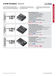
maxon motor control 1-Q-EC Amplifier <strong>DEC</strong> <strong>Module</strong> <strong>50</strong>/5<br />
Order number 380200<br />
<strong>Operating</strong> <strong>Instructions</strong> Edition May 2013<br />
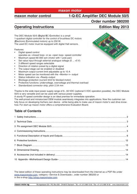
The <strong>DEC</strong> <strong>Module</strong> <strong>50</strong>/5 (Digital EC Controller) is a small<br />
1-quadrant digital controller for the control of brushless DC motors<br />
(Electronic Commutated motors) up to 2<strong>50</strong> W.<br />
The used EC motor must be equipped with digital Hall sensors.<br />
Features:<br />
• Digital speed control<br />
operates as «closed loop» or as «open loop» speed controller<br />
• Maximum speed 80 000 rpm (motor with 1 pole pair)<br />
• Set value input through external analogue volt<strong>ag</strong>e (0 ... +5 V)<br />
• 3 different speed ranges selectable<br />
• Direction of rotation preset by a digital signal<br />
• The output st<strong>ag</strong>e can be enabled or disabled<br />
• Maximum output current limit adjustable up to 10 A<br />
• <strong>Motor</strong> speed can be monitored with the «Monitor n» output<br />
• Status indication via «Ready»output<br />
• Block<strong>ag</strong>e protection (current limit for blocked motor)<br />
• Protective functions: undervolt<strong>ag</strong>e, overvolt<strong>ag</strong>e and thermal overload<br />
• Standardized connector strip, pitch 2.54 mm<br />
Thanks to the wide input power supply range of 6...<strong>50</strong> VDC (optional 5 VDC operation possible), the <strong>DEC</strong> <strong>Module</strong><br />
<strong>50</strong>/5 is very versatile and can be used with various power supplies.<br />
A sturdy PI speed controller design is an ideal premise for immediate operation.<br />
The well-priced and miniaturized OEM module seamlessly integrates into applications. Now the customer can<br />
fully focus on developing his/hers own device - while being able to make use of maxon motor‘s vast drive knowhow.<br />
For start-up maxon motor offers a comprehensive Evaluation Board.<br />
Table of Contents<br />
1 Safety <strong>Instructions</strong>.............................................................................................................................................. 2<br />
2 Technical Data.................................................................................................................................................... 3<br />
3 Pin assignment <strong>DEC</strong> <strong>Module</strong> <strong>50</strong>/5..................................................................................................................... 4<br />
4 Commissioning <strong>Instructions</strong>............................................................................................................................... 5<br />
5 Functional Description of Inputs and Outputs.................................................................................................... 6<br />
6 Protective functions.......................................................................................................................................... 12<br />
7 Block Di<strong>ag</strong>ram.................................................................................................................................................. 13<br />
8 Dimensional Drawing....................................................................................................................................... 14<br />
9 Accessories (not included in delivery).............................................................................................................. 14<br />
10 Appendix «Motherboard Design Guide»........................................................................................................ 14<br />
The latest edition of these operating instructions may be downloaded from the internet as a PDF-file under<br />
www.maxonmotor.com, category «Service & Downloads», order number 380200 or<br />
in the e-shop http://shop.maxonmotor.com.
1-Q-EC Amplifier <strong>DEC</strong> <strong>Module</strong> <strong>50</strong>/5<br />
1 Safety <strong>Instructions</strong><br />
maxon motor<br />
<strong>Operating</strong> <strong>Instructions</strong><br />
a Skilled Personnel<br />
Installation and commissioning of the equipment shall only be performed by<br />
experienced, skilled personnel.<br />
a Statutory Regulations<br />
The user must ensure that the amplifier and the components belonging to it<br />
are assembled and connected according to local statutory regulations.<br />
a Disconnect Load<br />
For primary operation the motor should be free running, i.e. with load disconnected.<br />
a Additional Safety Equipment<br />
Any electronic apparatus is, in principle, not fail-safe. Machines and apparatus<br />
must therefore be fitted with independent monitoring and safety equipment.<br />
If the equipment breaks down, if it is operated incorrectly, if the control<br />
unit breaks down or if the cables break, etc., it must be ensured that the drive<br />
or the complete apparatus is kept in a safe operating mode.<br />
a Repairs<br />
Repairs may be made by authorized personnel only or by the manufacturer.<br />
Improper repairs can result in substantial dangers for the user<br />
a Danger<br />
During installation of the <strong>DEC</strong> <strong>Module</strong>, make sure to disconnect all apparatus<br />
from the electrical supply.<br />
After switch-on, do not touch any life parts!<br />
a Wiring Procedure<br />
All electrical connections should only be connected or disconnected when the<br />
power is switched off.<br />
a Max. Supply volt<strong>ag</strong>e<br />
Make sure that the supply volt<strong>ag</strong>e is between 6 and 55 VDC. Volt<strong>ag</strong>e higher<br />
than 56 VDC or wrong polarity will destroy the unit.<br />
a Short Circuit and Earth Fault<br />
The amplifier is not protected <strong>ag</strong>ainst winding short circuits <strong>ag</strong>ainst ground<br />
safety earth and/or GND!<br />
a Electrostatic sensitive device (ESD)<br />
2 maxon motor control<br />
May 2013 Edition / document number 1094861PDFE 1094861PDFE _PDF_E - 04 / subject to change
maxon motor<br />
<strong>Operating</strong> <strong>Instructions</strong> 1-Q-EC Amplifier <strong>DEC</strong> <strong>Module</strong> <strong>50</strong>/5<br />
2 Technical Data<br />
2.1 Electrical data<br />
2.2 Inputs<br />
2.3 Output<br />
2.4 Volt<strong>ag</strong>e output<br />
Nominal supply volt<strong>ag</strong>e +V CC<br />
..................................................................... 6 … <strong>50</strong> VDC (optional 5 VDC 1 )<br />
Absolute minimum supply volt<strong>ag</strong>e +V cc min<br />
...........................................................6 VDC (optional 5 VDC 1 )<br />
Absolute maximum supply volt<strong>ag</strong>e +V cc max<br />
.................................................................................... 55 VDC<br />
Max. output volt<strong>ag</strong>e...................................................................................................................... 0.95 • V CC<br />
Continuous output current I cont<br />
.................................................................................................................5 A<br />
Max. output current I max<br />
.........................................................................................................................10 A<br />
Switching frequency.......................................................................................................................46.8 kHz<br />
Max. speed (motor with 1 pole pair)......................................................................................... 80 000 rpm<br />
«Set value speed».........................................................Analogue input (0 ... 5 V); Resolution: 1024 steps<br />
«Enable».......................................................................+2.4 … +55 V (R i<br />
= 100 kΩ) or switch <strong>ag</strong>ainst V CC<br />
«Direction»...................................................................+2.4 … +55 V (R i<br />
= 100 kΩ) or switch <strong>ag</strong>ainst V CC<br />
Speed range «DigIN1 »...............................+2.4 … +55 V (R pull-up<br />
= 47 kΩ at 5 V) or switch <strong>ag</strong>ainst Gnd<br />
Speed range «DigIN2 »...............................+2.4 … +55 V (R pull-up<br />
= 47 kΩ at 5 V) or switch <strong>ag</strong>ainst Gnd<br />
«Set current limit».............................................................................external resistor ( 1 / 16<br />
W) <strong>ag</strong>ainst Gnd<br />
Hall sensors.................................................................«Hall sensor 1», «Hall sensor 2», «Hall sensor 3»<br />
<strong>Motor</strong> speed «Monitor n»................................................................ Digital output signal, 5 V (R o<br />
= 47 kΩ)<br />
Status indication «Ready».............................................................. Digital output signal, 5 V (R o<br />
= 47 kΩ)<br />
+5 VDC output volt<strong>ag</strong>e «V CC<br />
Hall».............................................................................+5 VDC, max. 35 mA<br />
2.5 <strong>Motor</strong> connections<br />
<strong>Motor</strong> connections....................................... «<strong>Motor</strong> winding 1», « <strong>Motor</strong> winding 2», « <strong>Motor</strong> winding 3»<br />
2.6 Ambient temperature<br />
Operation..................................................................................................................................-10 ... +45°C<br />
Stor<strong>ag</strong>e.....................................................................................................................................-40 ... +85°C<br />
2.7 Humidity range<br />
Non condensating.......................................................................................................................20 ... 80 %<br />
2.8 Protective functions<br />
Current limitation (cycle-by-cycle)............................................................ adjustable up to maximum 10 A<br />
Block<strong>ag</strong>e ......................................................................... <strong>Motor</strong> current limitation if motor shaft is blocked<br />
Undervolt<strong>ag</strong>e shutdown....................................................................................... shutdown if V CC<br />
< 6 VDC<br />
Overvolt<strong>ag</strong>e shutdown.......................................................................................shutdown if V CC<br />
> 56 VDC<br />
Thermal overload protection of power st<strong>ag</strong>e............................................... shutdown if T power st<strong>ag</strong>e<br />
> 100°C<br />
2.9 Mechanical data<br />
2.10 Terminals<br />
Weight......................................................................................................................................... approx. 9 g<br />
Dimensions (LxWxH).......................................................................................... 43.18 x 27.94 x 12.7 mm<br />
....................................................................................................................................... 1.7 x 1.1 x 0.5 Inch<br />
Pin header 1..................................................................................................................................2 x 9 pins<br />
.......................................................................................................... double-row, pitch 2.54 mm (0.1 Inch)<br />
Pin header 2....................................................................................................................................... 8 pins<br />
............................................................................................................single row, pitch 2.54 mm (0.1 Inch)<br />
1 5V operating see chapter «10.8.2 Low Volt<strong>ag</strong>e +5V operation»<br />
May 2013 Edition / document number 1094861PDFE 1094861PDFE _PDF_E - 04 / subject to change<br />
maxon motor control 3
maxon motor<br />
1-Q-EC Amplifier <strong>DEC</strong> <strong>Module</strong> <strong>50</strong>/5<br />
3 Pin assignment <strong>DEC</strong> <strong>Module</strong> <strong>50</strong>/5<br />
Top view<br />
<strong>Operating</strong> <strong>Instructions</strong><br />
1 2<br />
<strong>DEC</strong> <strong>Module</strong> <strong>50</strong>/5<br />
26<br />
17 18<br />
19<br />
3.1 Pin assignment<br />
Pin Signal Description<br />
1 W1 <strong>Motor</strong> winding 1<br />
2 W1 <strong>Motor</strong> winding 1<br />
3 W2 <strong>Motor</strong> winding 2<br />
4 W2 <strong>Motor</strong> winding 2<br />
5 W3 <strong>Motor</strong> winding 3<br />
6 W3 <strong>Motor</strong> winding 3<br />
7 +Vcc Supply volt<strong>ag</strong>e 6...<strong>50</strong> VDC<br />
8 +Vcc Supply volt<strong>ag</strong>e 6...<strong>50</strong> VDC<br />
9 Gnd Ground<br />
10 Gnd Ground<br />
11 Vcc Hall +5 VDC output volt<strong>ag</strong>e<br />
12 n.c. do not connect<br />
13 H1 Hall sensor 1<br />
14 Gnd Ground<br />
15 H2 Hall sensor 2<br />
16 Gnd Ground<br />
17 H3 Hall sensor 3<br />
18 Monitor n Speed monitor output<br />
19 Ready Status indication output<br />
20 DigIN1 Digital input 1<br />
21 DigIN2 Digital input 2<br />
22 Enable Enable input<br />
23 Direction Direction input<br />
24 Gnd Ground<br />
25 Set current limit Set current limit input<br />
26 Set value speed Set value speed input<br />
4 maxon motor control<br />
May 2013 Edition / document number 1094861PDFE 1094861PDFE _PDF_E - 04 / subject to change
maxon motor<br />
<strong>Operating</strong> <strong>Instructions</strong> 1-Q-EC Amplifier <strong>DEC</strong> <strong>Module</strong> <strong>50</strong>/5<br />
4 Commissioning <strong>Instructions</strong><br />
4.1 Power supply layout<br />
Any available power supply can be used, as long as it meets the minimum<br />
requirements shown below.<br />
During commissioning and adjustment phases, we recommend to mechanically<br />
separate the motor from the machine to prevent dam<strong>ag</strong>e due to uncontrolled<br />
motion!<br />
Power supply requirements<br />
Nominal output volt<strong>ag</strong>e<br />
Absolute minimum output volt<strong>ag</strong>e<br />
Absolute maximum output volt<strong>ag</strong>e<br />
Output current<br />
6 VDC < V CC<br />
< <strong>50</strong> VDC<br />
6 VDC<br />
55 VDC<br />
depending on load, continuous max. 5 A<br />
acceleration, short-time max. 10 A<br />
The required supply volt<strong>ag</strong>e can be calculated as follows:<br />
Known values<br />
ÖÖ<br />
<strong>Operating</strong> torque M B<br />
[mNm]<br />
ÖÖ<br />
ÖÖ<br />
ÖÖ<br />
ÖÖ<br />
<strong>Operating</strong> speed n B<br />
[rpm]<br />
Nominal motor volt<strong>ag</strong>e U N<br />
[V]<br />
<strong>Motor</strong> no-load speed at U N<br />
, n 0<br />
[rpm]<br />
Speed/torque gradient of the motor Dn/∆M [rpm/mNm]<br />
Sought value<br />
ÖÖ<br />
Supply volt<strong>ag</strong>e V CC<br />
[V]<br />
Solution<br />
U<br />
N n<br />
1<br />
Vcc nB<br />
M<br />
B 0. 3V<br />
n M<br />
0.95<br />
o<br />
Select a power supply capable of supplying this calculated volt<strong>ag</strong>e under<br />
load. The formula takes into account a maximum PWM duty cycle of 95%<br />
and a 0.3 V maximum volt<strong>ag</strong>e drop (at maximum output current) of the power<br />
st<strong>ag</strong>e.<br />
What speed can be reached with a given power supply:<br />
<br />
0.95<br />
<br />
<br />
<br />
<br />
<br />
n<br />
<br />
M<br />
<br />
V<br />
0.3V<br />
<br />
M<br />
<br />
0<br />
nB<br />
cc<br />
U<br />
N<br />
n<br />
Note<br />
ÖÖ<br />
During controlled deceleration, the power supply must be able to buffer<br />
the back-fed energy e.g. in a capacitor.<br />
ÖÖ<br />
The under volt<strong>ag</strong>e protection switches off the <strong>DEC</strong> <strong>Module</strong> <strong>50</strong>/5, as soon<br />
as the supply volt<strong>ag</strong>e V CC<br />
drops below 6 V. Therefore, at low supply volt<strong>ag</strong>e<br />
V CC<br />
attention has to be payed to the volt<strong>ag</strong>e drop over the supplying<br />
cables.<br />
B<br />
May 2013 Edition / document number 1094861PDFE 1094861PDFE _PDF_E - 04 / subject to change<br />
maxon motor control 5
1-Q-EC Amplifier <strong>DEC</strong> <strong>Module</strong> <strong>50</strong>/5<br />
maxon motor<br />
5 Functional Description of Inputs and Outputs<br />
<strong>Operating</strong> <strong>Instructions</strong><br />
5.1 Inputs<br />
5.1.1 Speed range and mode selection with «DigIN1» and «DigIN2»<br />
The digital inputs «DigIN1» [20] and «DigIN2» [21] determine both, the operation<br />
mode (digital speed controller or digital speed actuator) and the speed<br />
range in speed set value mode.<br />
<strong>Motor</strong> type<br />
DigIN1 DigIN2 1 pole pair 4 pole pair 8 pole pair<br />
0 0<br />
Open loop speed control, 0...95 % PWM<br />
depending on the «Set value speed» input volt<strong>ag</strong>e<br />
1 0 <strong>50</strong>0...5 000 rpm 125...1 2<strong>50</strong> rpm 62...625 rpm<br />
0 1 <strong>50</strong>0...20 000 rpm 125... 5 000 rpm 62...2 <strong>50</strong>0 rpm<br />
1 1 <strong>50</strong>0...80 000 rpm 125...20 000 rpm 62...10 000 rpm<br />
Please note<br />
ÖÖ<br />
If the signal level of the digital inputs DigIN1 [20] and DigIN2 [21] are<br />
changed, the new levels are adopted by a disable-enable procedure.<br />
Logic 1<br />
Logic 0<br />
If the input «DigIN» is not connected (floating) or a volt<strong>ag</strong>e higher than 2.4 V<br />
is applied, the input is active.<br />
Input not connected (floating)<br />
Input volt<strong>ag</strong>e > 2.4 V<br />
Input active<br />
If the input «DigIN» is set to ground potential or a volt<strong>ag</strong>e smaller than 0.8 V<br />
is applied, the digital input is inactive<br />
Input set to Gnd<br />
Input volt<strong>ag</strong>e < 0.8 V<br />
Input inactive<br />
The inputs «DigIN1»and «DigIN2» are protected <strong>ag</strong>ainst overvolt<strong>ag</strong>e.<br />
Digital input 1<br />
Digital input 2<br />
Input volt<strong>ag</strong>e range<br />
Input impedance<br />
Continuous overvolt<strong>ag</strong>e protection<br />
Pin number [20] «DigIN1»<br />
Pin number [21] «DigIN2»<br />
0 ... +5 V<br />
47 kΩ pull-up resistor <strong>ag</strong>ainst 5 V<br />
-55 ... +55 V<br />
6 maxon motor control<br />
May 2013 Edition / document number 1094861PDFE 1094861PDFE _PDF_E - 04 / subject to change
maxon motor<br />
<strong>Operating</strong> <strong>Instructions</strong> 1-Q-EC Amplifier <strong>DEC</strong> <strong>Module</strong> <strong>50</strong>/5<br />
5.1.2 Set value «Set value speed»<br />
The external analogue set value is predetermined at the «Set value speed»<br />
input [26]. The «Set value speed» input sets the rotational speed of the motor<br />
shaft.<br />
By adjusting the signal levels on digital inputs «DigIN1 [20]» and<br />
«DigIN2 [21]» the speed range must be set in advance.<br />
<strong>Motor</strong> type<br />
DigIN1 DigIN2 1 pole pair 4 pole pair 8 pole pair<br />
0 0<br />
Open loop speed control, 0...95 % PWM<br />
depending on the «Set value speed» input volt<strong>ag</strong>e<br />
1 0 <strong>50</strong>0...5 000 rpm 125...1 2<strong>50</strong> rpm 62...625 rpm<br />
0 1 <strong>50</strong>0...20 000 rpm 125...5 000 rpm 62...2 <strong>50</strong>0 rpm<br />
1 1 <strong>50</strong>0...80 000 rpm 125...20 000 rpm 62...10 000 rpm<br />
Note<br />
ÖÖ<br />
If the signal level of the digital inputs DigIN1 [20] and DigIN2 [21] are<br />
changed, the new levels are adopted by a disable-enable procedure.<br />
Set value volt<strong>ag</strong>e<br />
Description<br />
0 V ... 0.1 V Operation at minimum speed<br />
0.1 V ... 5.0 V Linear speed adjustment<br />
The actual speed value is calculated according the following formula:<br />
Known values<br />
Minimum speed (see table above) n min<br />
[rpm]<br />
Maximum speed (see table above) n max<br />
[rpm]<br />
Set value volt<strong>ag</strong>e V set<br />
[V] respectively speed n [rpm]<br />
Sought value<br />
speed n [rpm]<br />
Solution<br />
0.1V<br />
<br />
<br />
nmax<br />
nmin<br />
nmin<br />
V<br />
<br />
<br />
Vset <br />
n <br />
<br />
4.9<br />
<br />
Sought value<br />
Set value volt<strong>ag</strong>e V set<br />
[V]<br />
Solution<br />
n nmin<br />
<br />
V set <br />
4.9V<br />
0. 1<br />
nmax<br />
n<br />
<br />
min <br />
V<br />
<br />
The «Set value speed» input is protected <strong>ag</strong>ainst overvolt<strong>ag</strong>e.<br />
Set value speed input<br />
Pin number [26] «Set value speed»<br />
Input volt<strong>ag</strong>e range<br />
0 ... +5 V (referenced to Gnd)<br />
Resolution<br />
1024 steps (4.88 mV)<br />
Input impedance 107 kΩ (in range 0 ... +5 V)<br />
Continuous overvolt<strong>ag</strong>e protection -55 ... +55 V<br />
May 2013 Edition / document number 1094861PDFE 1094861PDFE _PDF_E - 04 / subject to change<br />
maxon motor control 7
1-Q-EC Amplifier <strong>DEC</strong> <strong>Module</strong> <strong>50</strong>/5<br />
5.1.3 «Enable»<br />
maxon motor<br />
The «Enable» input enables or disables the power st<strong>ag</strong>e.<br />
<strong>Operating</strong> <strong>Instructions</strong><br />
If a volt<strong>ag</strong>e higher than 2.4 V is applied to the «Enable» input, the amplifier is<br />
activated (Enable). A speed ramp will be performed during acceleration.<br />
Enable Input volt<strong>ag</strong>e > 2.4 V <strong>Motor</strong> shaft running<br />
Disable<br />
If the input is not connected (floating) or ground potential is applied to the<br />
«Enable» input, the power st<strong>ag</strong>e is high impedant and the motor shaft freewheels<br />
and slows down (Disable).<br />
Input not connected (floating)<br />
Input set to Gnd<br />
Input volt<strong>ag</strong>e < 0.8 V<br />
Power st<strong>ag</strong>e switched off<br />
The «Enable» input is protected <strong>ag</strong>ainst overvolt<strong>ag</strong>e.<br />
Enable<br />
Pin number [22] «Enable»<br />
Input volt<strong>ag</strong>e range<br />
0 ... +5 V<br />
Input impedance 100 kΩ (in range 0 ... +5 V)<br />
Continuous overvolt<strong>ag</strong>e protection -55 ... +55 V<br />
Delay time<br />
max. 40 ms<br />
5.1.4 «Direction»<br />
The «Direction» input determines the rotational direction of the motor shaft.<br />
When the level changes, the motor shaft slows down with a ramp to standstill,<br />
and accelerates with a speed ramp in the opposite direction, until the target<br />
speed is reached <strong>ag</strong>ain.<br />
CW<br />
If the input is not connected (floating) or ground potential is applied to the<br />
«Direction» input, the motor shaft runs clockwise (CW).<br />
Input not connected (floating)<br />
Input set to Gnd<br />
Input volt<strong>ag</strong>e < 0.8 V<br />
Clockwise (CW)<br />
If a volt<strong>ag</strong>e higher than 2.4 V is applied to the «Direction» input, the motor<br />
shaft runs counter-clockwise (CCW).<br />
CCW Input volt<strong>ag</strong>e > 2.4 V Counter-clockwise (CCW)<br />
The «Direction» input is protected <strong>ag</strong>ainst overvolt<strong>ag</strong>e.<br />
Direction<br />
Pin number [23] «Direction»<br />
Input volt<strong>ag</strong>e range<br />
0 ... +5 V<br />
Input impedance 100 kΩ (in range 0 ... +5 V)<br />
Continuous overvolt<strong>ag</strong>e protection -55 ... +55 V<br />
Delay time<br />
max. 40 ms<br />
8 maxon motor control<br />
May 2013 Edition / document number 1094861PDFE 1094861PDFE _PDF_E - 04 / subject to change
maxon motor<br />
<strong>Operating</strong> <strong>Instructions</strong> 1-Q-EC Amplifier <strong>DEC</strong> <strong>Module</strong> <strong>50</strong>/5<br />
5.1.5 «Set current limit»<br />
The «Set current limit» input is used for setting the continuous output current<br />
limitation in the range of 0.5...10 A.<br />
The current set at the input «Set current limit» will stay available for an indefinite<br />
period of time.<br />
Note<br />
ÖÖ<br />
The limiting value should be below the rated motor current (max. continuous<br />
current) as shown on the motor data sheet (corresponds to line 6 in<br />
maxon catalog).<br />
Set value current<br />
Referenced to Ground<br />
Pin number [25] «Set current limit»<br />
Pin number [24] «Gnd»<br />
To parameterize the preferred current limiting value, an external resistor (at<br />
least 62.5 mW) between current limiting input «Set current limit» Pin [25] and<br />
ground «Gnd» Pin [24] must be added.<br />
Current limit value<br />
Resistance value (E24 series)<br />
10 A input floating<br />
9 A 220 kΩ<br />
8 A 91 kΩ<br />
7 A 56 kΩ<br />
6 A 36 kΩ<br />
5 A 24 kΩ<br />
4 A 16 kΩ<br />
3 A 10.0 kΩ<br />
2 A 5.6 kΩ<br />
1 A 2.7 kΩ<br />
0.5 A 1.2 kΩ<br />
5.1.6 «Hall sensor 1», «Hall sensor 2», «Hall sensor 3»<br />
Hall sensors are needed for detecting the rotor position and the actual speed.<br />
The Hall sensor inputs are protected <strong>ag</strong>ainst overvolt<strong>ag</strong>e.<br />
Hall sensor 1 Pin number [13] «Hall sensor 1»<br />
Hall sensor 2 Pin number [15] «Hall sensor 2»<br />
Hall sensor 3 Pin number [17] «Hall sensor 3»<br />
Input volt<strong>ag</strong>e range<br />
Input impedance<br />
Volt<strong>ag</strong>e level «low»<br />
Volt<strong>ag</strong>e level «high»<br />
Continuous overvolt<strong>ag</strong>e protection<br />
0 ... +5 V<br />
22 kΩ pull-up resistor to 5 V<br />
max. 0.8 V<br />
min. 2.4 V<br />
-30 ... +30 V<br />
Suitable for Hall sensor IC‘s with Schmitt-Trigger behavior and open collector<br />
or push-pull outputs.<br />
May 2013 Edition / document number 1094861PDFE 1094861PDFE _PDF_E - 04 / subject to change<br />
maxon motor control 9
1-Q-EC Amplifier <strong>DEC</strong> <strong>Module</strong> <strong>50</strong>/5<br />
5.2 Outputs<br />
5.2.1 +5 VDC output volt<strong>ag</strong>e «V CC<br />
Hall»<br />
maxon motor<br />
An internal auxiliary volt<strong>ag</strong>e of +5 VDC is provided for:<br />
ÖÖ<br />
Hall sensor supply volt<strong>ag</strong>e «V CC<br />
Hall»<br />
ÖÖ<br />
ÖÖ<br />
<strong>Operating</strong> <strong>Instructions</strong><br />
For external set value potentiometer (recommended value: 10 kΩ)<br />
Gating the signals: «Enable» and «Direction»<br />
The output is protected <strong>ag</strong>ainst continuous short circuit.<br />
5.2.2 <strong>Motor</strong> speed monitor «Monitor n»<br />
+5 VDC output volt<strong>ag</strong>e Pin number [11] «V CC<br />
Hall»<br />
Referenced to Ground<br />
Pin number [14] «Gnd»<br />
Output volt<strong>ag</strong>e +5 VDC ± 5 %<br />
Max. output current<br />
35 mA<br />
The «Monitor n» output gives information on the actual speed of the motor<br />
shaft. The actual speed is available as a digital frequency signal (High/Low).<br />
The output «Monitor n» is protected <strong>ag</strong>ainst continuous short circuit.<br />
<strong>Motor</strong> speed monitor Pin number [18] «Monitor n»<br />
Output volt<strong>ag</strong>e range<br />
0 ... +5 V<br />
Output impedance<br />
47 kW<br />
Known values<br />
Number of pole pairs of motor z pol<br />
Frequency at «Monitor n» output [Hz] respectively Speed n [rpm]<br />
Sought value<br />
Frequency at «Monitor n» [Hz]<br />
Solution<br />
Sought value<br />
Speed n [rpm]<br />
Solution<br />
f<br />
Monitor n<br />
n z<br />
<br />
20<br />
pol<br />
<br />
Hz<br />
<br />
n <br />
f<br />
Monitor n<br />
z<br />
pol<br />
<br />
20<br />
<br />
min<br />
1<br />
<br />
10 maxon motor control<br />
May 2013 Edition / document number 1094861PDFE 1094861PDFE _PDF_E - 04 / subject to change
maxon motor<br />
<strong>Operating</strong> <strong>Instructions</strong> 1-Q-EC Amplifier <strong>DEC</strong> <strong>Module</strong> <strong>50</strong>/5<br />
5.2.3 Status indication «Ready»<br />
The «Ready» output can be used to report the state of operational readiness<br />
or a fault condition to a master control unit.<br />
In normal cases (no fault) the output is switched to 5V.<br />
Ready (no fault)<br />
5 V<br />
In case of a fault the output is switched to Ground.<br />
Fault (not ready)<br />
0 V (Gnd)<br />
Possible reasons for a fault mess<strong>ag</strong>e:<br />
ÖÖ<br />
Undervolt<strong>ag</strong>e<br />
Fault mess<strong>ag</strong>e occurs in case supply volt<strong>ag</strong>e +V CC<br />
< 6 VDC.<br />
To reset the fault condition the amplifier must be disabled and the supply<br />
volt<strong>ag</strong>e +V CC<br />
must be higher than 6 VDC.<br />
ÖÖ<br />
ÖÖ<br />
ÖÖ<br />
Overvolt<strong>ag</strong>e<br />
Fault mess<strong>ag</strong>e occurs in case supply volt<strong>ag</strong>e +V CC<br />
> 56 VDC.<br />
To reset the fault condition the amplifier must be disabled and the supply<br />
volt<strong>ag</strong>e +V CC<br />
must be lower than 54 VDC.<br />
Thermal overload<br />
Fault mess<strong>ag</strong>e occurs in case power st<strong>ag</strong>e temperature is > 100°C.<br />
To reset the fault condition the amplifier must be disabled and the power<br />
st<strong>ag</strong>e temperature must fall below 80°C<br />
Invalid Hall sensor signals<br />
The amplifier recognizes invalid conditions at the Hall sensor inputs.<br />
To reset the fault condition the amplifier must be disabled and the Hall<br />
sensors must be wired correctly.<br />
The output «Ready» is protected <strong>ag</strong>ainst continuous short circuit.<br />
Status indication<br />
Output volt<strong>ag</strong>e range<br />
Output resistance<br />
Pin number [19] «Ready»<br />
0 ... +5 V<br />
47 kΩ<br />
May 2013 Edition / document number 1094861PDFE 1094861PDFE _PDF_E - 04 / subject to change<br />
maxon motor control 11
1-Q-EC Amplifier <strong>DEC</strong> <strong>Module</strong> <strong>50</strong>/5<br />
6 Protective functions<br />
maxon motor<br />
<strong>Operating</strong> <strong>Instructions</strong><br />
6.1 Undervolt<strong>ag</strong>e protection<br />
The power st<strong>ag</strong>e will be disabled in case the supply volt<strong>ag</strong>e +V CC<br />
drops below<br />
6 VDC.<br />
To reset the fault condition the amplifier must be disabled and the supply<br />
volt<strong>ag</strong>e +V CC<br />
must be higher than 6 VDC.<br />
6.2 Overvolt<strong>ag</strong>e protection<br />
The power st<strong>ag</strong>e will be disabled in case the supply volt<strong>ag</strong>e +V CC<br />
rises above<br />
56 VDC.<br />
To reset the fault condition the amplifier must be disabled and the supply<br />
volt<strong>ag</strong>e +V CC<br />
must be lower than 54 VDC.<br />
6.3 Thermal overload protection<br />
The power st<strong>ag</strong>e will be disabled in case the power st<strong>ag</strong>e temperature exceeds<br />
100°C.<br />
To reset the fault condition the amplifier must be disabled and the power<br />
st<strong>ag</strong>e temperature must fall below 80°C.<br />
6.4 Invalid Hall sensor signals<br />
The power st<strong>ag</strong>e will be disabled in case invalid conditions at the Hall sensor<br />
inputs occur.<br />
To reset the fault condition the amplifier must be disabled and the Hall sensors<br />
must be wired correctly.<br />
6.5 Block<strong>ag</strong>e protection<br />
6.6 Current limitation<br />
If the motor shaft is blocked, the current limit is set to the predetermined value<br />
at the«Set current limit» input.<br />
Note<br />
ÖÖ<br />
No fault mess<strong>ag</strong>e occurs at the «Ready» output if block<strong>ag</strong>e protection is<br />
active.<br />
The motor current will be limited to 0.5…10 A depending on the value applied<br />
to the input «Set current limit» by means of a cycle-to-cycle limitation (see<br />
chapter «5.1.5 «Set current limit»»).<br />
Note<br />
ÖÖ<br />
No fault mess<strong>ag</strong>e occurs at the «Ready» output if current limitation is<br />
active.<br />
12 maxon motor control<br />
May 2013 Edition / document number 1094861PDFE 1094861PDFE _PDF_E - 04 / subject to change
maxon motor<br />
<strong>Operating</strong> <strong>Instructions</strong> 1-Q-EC Amplifier <strong>DEC</strong> <strong>Module</strong> <strong>50</strong>/5<br />
7 Block Di<strong>ag</strong>ram<br />
May 2013 Edition / document number 1094861PDFE 1094861PDFE _PDF_E - 04 / subject to change<br />
maxon motor control 13
1-Q-EC Amplifier <strong>DEC</strong> <strong>Module</strong> <strong>50</strong>/5<br />
8 Dimensional Drawing<br />
Dimensions in [mm]<br />
maxon motor<br />
<strong>Operating</strong> <strong>Instructions</strong><br />
9 Accessories (not included in delivery)<br />
10 Appendix «Motherboard Design Guide»<br />
maxon motor order number<br />
Designation<br />
370652 <strong>DEC</strong> <strong>Module</strong> Evaluation Board<br />
10.1 Introduction<br />
The present documentation «Motherboard Design Guide» contains helpful<br />
information on the integration of the <strong>DEC</strong> <strong>Module</strong>s <strong>50</strong>/5 into printed circuit<br />
boards. Contained therein are recommendations for possibly needed 3rd party<br />
components, suggestions on layout, terminal assignment as well as circuit<br />
samples.<br />
10.2 External components<br />
10.2.1 Pin socket<br />
Warning:<br />
Development of printed circuits boards requires specific qualifications and<br />
should only be performed by experienced electronics engineers.<br />
The present brief instruction is intended to serve as supporting aid only and<br />
does not claim completeness. Upon request, maxon motor <strong>ag</strong> is glad to assist<br />
and to offer customer-specific motherboard designs.<br />
The connector arrays used in the <strong>DEC</strong> <strong>Module</strong> <strong>50</strong>/5 permit two possible types<br />
of connections. The module can either be mounted on pin socket or soldered<br />
directly into the printed circuit board.<br />
Pin socket recommendations:<br />
Specifications:<br />
––<br />
Pin socket vertical, single row, mates with pin header 0.63 x 0.63 mm,<br />
pitch 2.54 mm, 3 A, contact material gold or brass<br />
Pin socket 8 poles, single row:<br />
––<br />
Preci-Dip 801-87-008-10-001101<br />
––<br />
Samtec SSW-108-01-F-S<br />
––<br />
Harwin M20-7820842<br />
Pin socket 9 poles, double row<br />
––<br />
Preci-Dip 803-87-018-10-001101<br />
––<br />
Samtec SSW-109-01-F-D<br />
––<br />
Harwin M20-7830942<br />
14 maxon motor control<br />
May 2013 Edition / document number 1094861PDFE 1094861PDFE _PDF_E - 04 / subject to change
maxon motor<br />
<strong>Operating</strong> <strong>Instructions</strong> 1-Q-EC Amplifier <strong>DEC</strong> <strong>Module</strong> <strong>50</strong>/5<br />
10.2.2 Supply volt<strong>ag</strong>e<br />
To protect the <strong>DEC</strong> module from dam<strong>ag</strong>e an external fuse, a TVS-diode and<br />
a capacitor in the power supply volt<strong>ag</strong>e line are recommended.<br />
FU1<br />
+VSupply +Vcc <strong>Module</strong> 1<br />
7A<br />
D1<br />
SMBJ54A<br />
+<br />
C1<br />
220u/63V<br />
Gnd<br />
Gnd<br />
Fuse FU1:<br />
To protect <strong>ag</strong>ainst reverse polarity, place a fuse at the entry of the power<br />
supply. Together with the TVS-diode, the fuse breaks an occurring reverse<br />
current.<br />
Recommendation for the fuse:<br />
––<br />
Littlefuse 154 Series OMNI-BLOK ® fuse holder with SMD NANO 2 ® Fuse<br />
installed:<br />
154007. 7 A very fast-acting<br />
TVS-Diode D1:<br />
To protect <strong>ag</strong>ainst overvolt<strong>ag</strong>e due to supply transients or the motor braking<br />
energy, connect a transient volt<strong>ag</strong>e suppressor diode to the power supply<br />
volt<strong>ag</strong>e.<br />
Recommendations for the TVS-diode:<br />
––<br />
Vishay SMBJ54A<br />
U R<br />
=54 V, U BR<br />
= 60.0...66.3 V @1mA, U C<br />
= 87.1 V @ 6.9 A<br />
––<br />
Diotec P6SMBJ54A<br />
U R<br />
=54 V, U BR<br />
= 60.0...66.6 V @1mA, U C<br />
= 87.1 V @ 6.9 A<br />
Capacitor C1:<br />
An external capacitor is not mandatory for the function of the <strong>DEC</strong> module.<br />
To reduce the volt<strong>ag</strong>e ripple and to buffer the back-fed energy a electrolyte<br />
capacitor can be connect to the power supply volt<strong>ag</strong>e.<br />
Recommendations for the electrolyte capacitor:<br />
––<br />
Panasonic EEUFC1J221S<br />
Rated volt<strong>ag</strong>e 63V, Capacitance 220 mF, Ripple Current 1285 mA<br />
––<br />
Rubycon 63ZL220M10X23<br />
Rated volt<strong>ag</strong>e 63V, Capacitance 220 mF, Ripple Current 1120 mA<br />
––<br />
Nichicon UPM1J221MHD<br />
Rated volt<strong>ag</strong>e 63V, Capacitance 220 mF, Ripple Current 1300 mA<br />
May 2013 Edition / document number 1094861PDFE 1094861PDFE _PDF_E - 04 / subject to change<br />
maxon motor control 15
1-Q-EC Amplifier <strong>DEC</strong> <strong>Module</strong> <strong>50</strong>/5<br />
10.2.3 <strong>Motor</strong> phase<br />
maxon motor<br />
<strong>Operating</strong> <strong>Instructions</strong><br />
The <strong>DEC</strong> <strong>Module</strong> <strong>50</strong>/5 has no built-in chokes.<br />
For most motors and applications no additional motor chokes are necessary.<br />
In case of high power supply volt<strong>ag</strong>e +V CC<br />
and a motor with very low inductance<br />
the current ripple will become too high. This causes unnecessary motor<br />
heating and unstable control behavior. The minimum inductance of each<br />
choke can be calculated with the formula below.<br />
1 VCC<br />
L <br />
Phase<br />
<br />
0. 3<br />
L<br />
2 6 fPWM<br />
I<br />
N<br />
<strong>Motor</strong><br />
<br />
<br />
<br />
L Phase<br />
[H]<br />
V CC<br />
[V]<br />
f PWM<br />
[Hz]<br />
I N<br />
[A]<br />
L <strong>Motor</strong><br />
[H]<br />
Additional external inductance per phase<br />
Power supply volt<strong>ag</strong>e +V CC<br />
PWM frequency = 46 800 Hz<br />
Nominal motor current<br />
Terminal inductance phase to phase of the motor<br />
If the result of the formula is negative, no additional chokes are needed.<br />
The chokes must have an electrom<strong>ag</strong>netic shield, high saturation current, low<br />
losses and a rated current higher than the continuous motor current.<br />
Recommendations for the motor chokes:<br />
––<br />
Würth Elektronik WE-PD-XXL 7447709220<br />
L N<br />
= 22 μH, R DC<br />
= 23.3 mΩ, I DC<br />
= 5.3 A, I sat<br />
= 6.5 A, shielded<br />
––<br />
Coiltronics DR127-220<br />
L N<br />
= 22 μH, R DC<br />
= 39.1 mΩ, I DC<br />
= 4.0 A, I sat<br />
= 7.6 A, shielded<br />
––<br />
Würth Elektronik WE-PD-XXL 74477091<strong>50</strong><br />
L N<br />
= 15 μH, R DC<br />
= 21 mΩ, I DC<br />
= 6.5 A, I sat<br />
= 8.0 A, shielded<br />
––<br />
Sumida CDRH129RNP-1<strong>50</strong>MC<br />
L N<br />
= 15 μH, R DC<br />
= 16 mΩ, I DC<br />
= 6.0 A, I sat<br />
> 6.0 A, shielded<br />
––<br />
Coiltronics DR127-1<strong>50</strong><br />
L N<br />
= 15 μH, R DC<br />
= 25 mΩ, I DC<br />
= 5.0 A, I sat<br />
= 9.7 A, shielded<br />
––<br />
Bourns SRR1280-1<strong>50</strong>M<br />
L N<br />
= 15 μH, R DC<br />
= 28 mΩ, I DC<br />
= 5.2 A, I sat<br />
> 5.2 A, shielded<br />
––<br />
Würth Elektronik WE-PD-XL 744770115<br />
L N<br />
= 15 μH, R DC<br />
= 24 mΩ, I DC<br />
= 5.0 A, I sat<br />
= 6.0 A, shielded<br />
– – Sumida CDR127/LDNP-1<strong>50</strong>M<br />
L N<br />
= 15 μH, R DC<br />
= 20 mΩ, I DC<br />
= 5.7 A, I sat<br />
> 5.7 A, shielded<br />
16 maxon motor control<br />
May 2013 Edition / document number 1094861PDFE 1094861PDFE _PDF_E - 04 / subject to change
maxon motor<br />
<strong>Operating</strong> <strong>Instructions</strong> 1-Q-EC Amplifier <strong>DEC</strong> <strong>Module</strong> <strong>50</strong>/5<br />
10.3 Design rules<br />
To help customers designing an application specific motherboard and for<br />
correct and save function of the <strong>DEC</strong> <strong>Module</strong> <strong>50</strong>/5 these rules should be<br />
followed.<br />
10.3.1 Ground<br />
10.3.2 Layout<br />
a<br />
The ground (Gnd) pins of the <strong>DEC</strong> <strong>Module</strong> are internally connected (same<br />
electrical potential). It is common practice to place a ground plane on the motherboard<br />
and it is necessary to connect pins [9], [10], [14], [16] and [24] with<br />
thick tracks to the power supply volt<strong>ag</strong>e ground<br />
Pin Signals Description<br />
9 Gnd Ground<br />
10 Gnd Ground<br />
14 Gnd Ground<br />
16 Gnd Ground<br />
24 Gnd Ground<br />
If ground safety earth is mandatory, connect the ground plane over several<br />
parallel capacitors to the ground safety earth. Ceramic chip capacitors with<br />
47 nF and 100 V are suggested.<br />
Motherboard layouts for <strong>DEC</strong> <strong>Module</strong> <strong>50</strong>/5 should follow these rules:<br />
––<br />
Pins [7] and [8] +V CC<br />
: Use thick track to connect to the fuse.<br />
––<br />
Pins [9], [10], [14], [16] and [24]: Use thick tracks to connect to supply<br />
volt<strong>ag</strong>e‘s ground (Gnd).<br />
––<br />
The width and copper plating thickness of the power supply volt<strong>ag</strong>e and<br />
motor winding traces depend on the maximum current expected in the<br />
application. A minimum of 75 mil width at 70 μm thickness is recommended.<br />
10.4 THT footprint<br />
Top view<br />
Dimensions in [mm]<br />
10.5 Pin description<br />
10.6 Technical data<br />
10.7 Dimensional drawing<br />
See chapter «3 Pin assignment <strong>DEC</strong> <strong>Module</strong> <strong>50</strong>/5»<br />
See chapter «2 Technical data»<br />
See chapter «8 Dimensional drawing»<br />
May 2013 Edition / document number 1094861PDFE 1094861PDFE _PDF_E - 04 / subject to change<br />
maxon motor control 17
1-Q-EC Amplifier <strong>DEC</strong> <strong>Module</strong> <strong>50</strong>/5<br />
10.8 Schematic examples<br />
10.8.1 Minimum external wiring<br />
maxon motor<br />
<strong>Operating</strong> <strong>Instructions</strong><br />
Power supply (6...<strong>50</strong> VDC); EC motor with Hall sensors; External set value<br />
speed potentiometer (10 kΩ); Enable switch<br />
Configuration: Speed controller (closed loop); Speed range <strong>50</strong>0...20 000 rpm.<br />
<strong>Motor</strong> Winding 1<br />
<strong>Motor</strong> Winding 2<br />
Vcc Hall<br />
<strong>Motor</strong> Winding 3<br />
+Vcc 6-<strong>50</strong>VDC<br />
Gnd<br />
Gnd<br />
Vcc Hall<br />
Hall sensor 1<br />
FU1<br />
7A<br />
Gnd<br />
Vcc Hall<br />
D1<br />
SMBJ54A<br />
1<br />
2<br />
3<br />
4<br />
5<br />
6<br />
7<br />
8<br />
9<br />
10<br />
11<br />
12<br />
13<br />
14<br />
15<br />
16<br />
17<br />
18<br />
IC1<br />
W1<br />
W1<br />
Set value speed<br />
W2<br />
W2<br />
Set current limit<br />
W3<br />
W3<br />
Gnd<br />
+Vcc<br />
+Vcc<br />
Direction<br />
Gnd<br />
Gnd<br />
Enable<br />
Vcc Hall<br />
Do not connect<br />
DigIn2<br />
Hall sensor 1<br />
Gnd<br />
DigIN1<br />
Hall sensor 2<br />
Gnd<br />
Ready<br />
Hall sensor 3<br />
Monitor n<br />
<strong>DEC</strong> <strong>Module</strong> <strong>50</strong>/5<br />
26<br />
25<br />
24<br />
23<br />
22<br />
21<br />
20<br />
19<br />
Gnd<br />
S1<br />
SW-SPST<br />
Gnd<br />
P1<br />
10k<br />
Vcc Hall<br />
speed range <strong>50</strong>0-20'000rpm<br />
Hall sensor 2<br />
Hall sensor 3<br />
10.8.2 Low Volt<strong>ag</strong>e +5V operation<br />
Alternatively, the <strong>DEC</strong> <strong>Module</strong> <strong>50</strong>/5 can be operated with a supply volt<strong>ag</strong>e of<br />
+5 VDC only. Thereby, the external +5 VDC power source must be connected<br />
to pins [7] and [8] «+V CC<br />
» and, in addition, also to pin [11] «V CC<br />
Hall». This<br />
wiring makes sure that the internally needed +5VDC supply volt<strong>ag</strong>e is fed<br />
from external.<br />
Warning<br />
The supply volt<strong>ag</strong>e must be between +4.75 VDC and +5.25 VDC. Volt<strong>ag</strong>es<br />
above +5.5 VDC or swapping poles will destroy the unit.<br />
<strong>Motor</strong> Winding 1<br />
<strong>Motor</strong> Winding 2<br />
Vcc Hall<br />
<strong>Motor</strong> Winding 3<br />
+Vcc 5VDC<br />
Gnd<br />
Gnd<br />
Vcc Hall<br />
Hall sensor 1<br />
FU1<br />
7A<br />
Gnd<br />
Vcc Hall<br />
C1<br />
10uF<br />
1<br />
2<br />
3<br />
4<br />
5<br />
6<br />
7<br />
8<br />
9<br />
10<br />
11<br />
12<br />
13<br />
14<br />
15<br />
16<br />
17<br />
18<br />
IC1<br />
W1<br />
W1<br />
Set value speed<br />
W2<br />
W2<br />
Set current limit<br />
W3<br />
W3<br />
Gnd<br />
+Vcc<br />
+Vcc<br />
Direction<br />
Gnd<br />
Gnd<br />
Enable<br />
Vcc Hall<br />
Do not connect<br />
DigIn2<br />
Hall sensor 1<br />
Gnd<br />
DigIN1<br />
Hall sensor 2<br />
Gnd<br />
Ready<br />
Hall sensor 3<br />
Monitor n<br />
<strong>DEC</strong> <strong>Module</strong> <strong>50</strong>/5<br />
26<br />
25<br />
24<br />
23<br />
22<br />
21<br />
20<br />
19<br />
Gnd<br />
S1<br />
SW-SPST<br />
Gnd<br />
P1<br />
10k<br />
Vcc Hall<br />
speed range <strong>50</strong>0-20'000rpm<br />
Hall sensor 2<br />
Hall sensor 3<br />
18 maxon motor control<br />
May 2013 Edition / document number 1094861PDFE 1094861PDFE _PDF_E - 04 / subject to change
maxon motor<br />
<strong>Operating</strong> <strong>Instructions</strong> 1-Q-EC Amplifier <strong>DEC</strong> <strong>Module</strong> <strong>50</strong>/5<br />
10.8.3 Maximum external wiring according to the <strong>DEC</strong> <strong>Module</strong> Evaluation Board order number 370652<br />
For initial commissioning, maxon motor offers an Evaluation Board for a<br />
single-axis system. The motherboard «<strong>DEC</strong> <strong>Module</strong> Evaluation Board» can<br />
be ordered with order number 370652.<br />
Evaluation Board schematic:<br />
Vcc Hall<br />
J1<br />
1<br />
2<br />
3<br />
Power<br />
ECH3<strong>50</strong>R-03P<br />
J2<br />
1<br />
2<br />
3<br />
4<br />
5<br />
6<br />
7<br />
8<br />
<strong>Motor</strong><br />
ECH3<strong>50</strong>R-08P<br />
J3<br />
1<br />
2<br />
3<br />
4<br />
5<br />
6<br />
7<br />
8<br />
<strong>Motor</strong><br />
2.5-MSFW/O-08<br />
J4<br />
1<br />
2<br />
3<br />
4<br />
5<br />
6<br />
7<br />
8<br />
9<br />
10<br />
11<br />
<strong>Motor</strong><br />
Molex-52207-1185<br />
J5<br />
1<br />
2<br />
3<br />
4<br />
5<br />
6<br />
7<br />
8<br />
<strong>Motor</strong><br />
Molex-52745-0896<br />
Gnd<br />
W3<br />
W2<br />
W1<br />
H3<br />
H2<br />
H1<br />
Vcc Hall<br />
Gnd<br />
W1<br />
W2<br />
W3<br />
Vcc Hall<br />
H1<br />
H2<br />
H3<br />
Vcc Hall<br />
H3<br />
H1<br />
H2<br />
W3<br />
W2<br />
W1<br />
W1<br />
W2<br />
W3<br />
Vcc Hall<br />
H1<br />
H2<br />
H3<br />
Gnd<br />
Gnd<br />
Gnd<br />
F1 7A<br />
L1<br />
W1<br />
22uH<br />
JP1<br />
L2<br />
W2<br />
22uH<br />
JP2<br />
L3<br />
W3<br />
22uH<br />
JP3<br />
H1<br />
Chassis_Gnd<br />
Gnd<br />
W1<br />
W2<br />
W3<br />
D2<br />
SMBJ54A<br />
C_W1 1<br />
2<br />
C_W2 3<br />
4<br />
C_W3 5<br />
6<br />
+<strong>50</strong>V 7<br />
8<br />
9<br />
Gnd<br />
10<br />
+VHall 11<br />
12<br />
H1 13<br />
14<br />
H2 15<br />
16<br />
H3 17<br />
Monitor n 18<br />
H2<br />
Chassis_Gnd<br />
+<strong>50</strong>V<br />
+ C9<br />
220u/63V<br />
Gnd<br />
IC1<br />
W1<br />
W1<br />
Set value speed<br />
W2<br />
W2<br />
Set current limit<br />
W3<br />
W3<br />
Gnd<br />
+Vcc<br />
+Vcc<br />
Direction<br />
Gnd<br />
Gnd<br />
Enable<br />
Vcc Hall<br />
Do not connect<br />
DigIn2<br />
Hall sensor 1<br />
Gnd<br />
DigIN1<br />
Hall sensor 2<br />
Gnd<br />
Ready<br />
Hall sensor 3<br />
Monitor n<br />
<strong>DEC</strong> <strong>Module</strong> <strong>50</strong>/5<br />
H3<br />
Chassis_Gnd<br />
26<br />
25<br />
24<br />
23<br />
22<br />
21<br />
20<br />
19<br />
H4<br />
Chassis_Gnd<br />
Set value speed<br />
Set current limit <strong>50</strong>/5<br />
Gnd<br />
Direction<br />
Enable<br />
Ready<br />
+VHall<br />
R2<br />
910R<br />
R3<br />
510R<br />
+VHall<br />
R4<br />
240R<br />
R7<br />
10k<br />
R8<br />
10k<br />
JP4<br />
R1<br />
220R<br />
Set value speed<br />
Set current limit <strong>50</strong>/5<br />
Direction<br />
Enable<br />
Ready<br />
Monitor n<br />
R5<br />
120R<br />
S3G<br />
S3H<br />
S3I<br />
S3J<br />
Gnd<br />
2<br />
2<br />
S3E<br />
S3F<br />
GND<br />
S2<br />
3<br />
SW-SPDT<br />
S1<br />
R6<br />
62R<br />
13 14<br />
15 16<br />
17 18<br />
19 20<br />
P1<br />
10k<br />
Vcc Hall<br />
1<br />
1<br />
3<br />
SW-SPDT<br />
8<br />
7<br />
6<br />
5<br />
4<br />
3<br />
2<br />
1<br />
9 10<br />
11 12<br />
Gnd<br />
J6<br />
Signal<br />
ECH3<strong>50</strong>R-08P<br />
Gnd<br />
Gnd<br />
DIP_SW7<br />
DIP_SW8<br />
DIP_SW9<br />
DIP_SW10<br />
DIP_SW5<br />
DIP_SW6<br />
C1<br />
470n<br />
C5<br />
2.2µ<br />
C2<br />
47n<br />
C6<br />
2.2µ<br />
C3<br />
47n<br />
C7<br />
2.2µ<br />
C4<br />
47n<br />
C8<br />
2.2µ<br />
R9<br />
10k<br />
R10<br />
470R<br />
D3<br />
red<br />
+VHall<br />
Gnd Gnd Gnd Gnd Gnd Gnd Gnd Gnd<br />
T1<br />
BC847BPN<br />
Gnd<br />
R11<br />
470R<br />
D4 green<br />
Gnd<br />
Set current limit <strong>50</strong>/5 (examples)<br />
DIP-SW 7 DIP-SW 8 DIP-SW 9 DIP-SW 10<br />
1.3A<br />
2.3A<br />
ON<br />
ON ON OFF<br />
ON ON OFF<br />
ON<br />
DIP-SW 5 DIP-SW 6<br />
DigIN2 DigIN1<br />
Speedrange<br />
1 pole pair<br />
4 pole pairs 8 pole pairs<br />
4.2A<br />
ON OFF ON<br />
ON<br />
ON<br />
ON<br />
Open loop speed control, 0...95% PWM<br />
6.3A<br />
ON<br />
OFF<br />
OFF<br />
OFF<br />
ON<br />
OFF<br />
<strong>50</strong>0...5'000 rpm<br />
125...1'2<strong>50</strong> rpm<br />
62...625 rpm<br />
7.2A<br />
OFF ON<br />
ON ON<br />
OFF<br />
ON<br />
<strong>50</strong>0...20'000 rpm<br />
125...5'000 rpm<br />
62...2'<strong>50</strong>0 rpm<br />
10A<br />
OFF OFF OFF OFF<br />
OFF<br />
OFF<br />
<strong>50</strong>0...80'000 rpm<br />
125...20'000 rpm<br />
62...10'000 rpm<br />
May 2013 Edition / document number 1094861PDFE 1094861PDFE _PDF_E - 04 / subject to change<br />
maxon motor control 19
1-Q-EC Amplifier <strong>DEC</strong> <strong>Module</strong> <strong>50</strong>/5<br />
Picture Evaluation Board with <strong>DEC</strong> <strong>Module</strong> <strong>50</strong>/5:<br />
maxon motor<br />
<strong>Operating</strong> <strong>Instructions</strong><br />
20 maxon motor control<br />
May 2013 Edition / document number 1094861PDFE 1094861PDFE _PDF_E - 04 / subject to change