EPOS Application Note: CANopen Basic Information - Maxon Motor ag
EPOS Application Note: CANopen Basic Information - Maxon Motor ag
EPOS Application Note: CANopen Basic Information - Maxon Motor ag

Create successful ePaper yourself
Turn your PDF publications into a flip-book with our unique Google optimized e-Paper software.
maxon motor control<br />
<strong>EPOS</strong> <strong>Application</strong> <strong>Note</strong>: <strong>CANopen</strong> <strong>Basic</strong> <strong>Information</strong> Edition May 2008<br />
<br />
Positioning Controller<br />
<strong>Application</strong> <strong>Note</strong><br />
"<strong>CANopen</strong> <strong>Basic</strong> <strong>Information</strong>"<br />
Edition May 2008<br />
<strong>EPOS</strong> 24/1, <strong>EPOS</strong> 24/5, <strong>EPOS</strong> 70/10, MCD <strong>EPOS</strong> 60W, <strong>EPOS</strong>2 50/5<br />
Firmware version 2000h or higher<br />
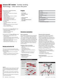
Introduction<br />
The <strong>EPOS</strong> positioning controller is a digital positioning system suitable for DC and EC (brushless) motors with<br />
incremental encoders in a modular pack<strong>ag</strong>e. The performance range of these compact positioning controllers<br />
ranges from a few watts up to 700 watts.<br />
A variety of operating modes allows all kinds of drive and automation systems to be flexibly assembled using<br />
positioning, speed and current regulation. The built-in <strong>CANopen</strong> interface allows networking to multiple axis drives<br />
and online commanding by CAN bus master units.<br />
For fast communication with several <strong>EPOS</strong> devices, use the <strong>CANopen</strong> protocol. The individual devices of a<br />
network are commanded by a <strong>CANopen</strong> master.<br />
Objectives<br />
This application note explains the functionality of the <strong>CANopen</strong> structure and protocol. The configuration process is<br />
explained step by step.<br />
References and Required Tool<br />
The latest editions of maxon motor documents and tools are freely available at http://www.maxonmotor.com<br />
category «Service & Downloads».<br />
Document<br />
Suitable order number for <strong>EPOS</strong> Positioning Controller<br />
<strong>EPOS</strong> Communication Guide<br />
<strong>EPOS</strong> Firmware Specification<br />
280937, 302267, 302287, 317270, 275512, 300583<br />
<strong>EPOS</strong>2 Communication Guide<br />
<strong>EPOS</strong>2 Firmware Specification<br />
347717<br />
<strong>CANopen</strong> documentation Specifications ‘DS-301 Version 4.02’ and ‘DSP-402 Version 2.0’<br />
CiA (CAN in Automation e. V.) http://www.can-cia.org<br />
Tool<br />
<strong>EPOS</strong> Studio Version 1.30 or higher 280937, 302267, 302287, 317270, 275512, 347717, 300583<br />
maxon motor <strong>ag</strong> Brünigstrasse 220 P.O. Box 263 CH-6072 Sachseln Tel.: 041/666 15 00 Fax: 041/666 16 50 www.maxonmotor.com
<strong>EPOS</strong> Positioning Controller<br />
maxon motor control<br />
<strong>EPOS</strong> <strong>Application</strong> <strong>Note</strong>: <strong>CANopen</strong> <strong>Basic</strong> <strong>Information</strong><br />
Network Structure<br />
The CAN interface of the maxon <strong>EPOS</strong> drives follows the CiA <strong>CANopen</strong> specification DS-301 Version 4.02<br />
<strong>Application</strong> Layer communication profile and the DSP 402 Version 2.0 Device Profile Drives and Motion Control.<br />
Figure 1: <strong>CANopen</strong> Network Structure<br />
The CAN-Bus line has to be terminated at both ends with a termination resistor of typically 120 Ω.<br />
Some <strong>EPOS</strong> Positioning Controller have an internal bus termination which can be switched on with a DIP-Switch:<br />
Device Bus terminated with 120 W DIP-Switch<br />
<strong>EPOS</strong> 24/5<br />
DIP-Switch 8 "ON"<br />
<strong>EPOS</strong>2 50/5<br />
DIP-Switch 9 “ON”:<br />
Figure 2: DIP-Switch bus termination<br />
2 maxon motor control Edition May 2008 / Subject to change
maxon motor control<br />
<strong>EPOS</strong> <strong>Application</strong> <strong>Note</strong>: <strong>CANopen</strong> <strong>Basic</strong> <strong>Information</strong><br />
<strong>EPOS</strong> Positioning Controller<br />
Configuration<br />
Follow the instructions step by step to set up a correct CAN communication.<br />
Step 1:<br />
<strong>CANopen</strong><br />
Master<br />
Use one of the PC CAN interface cards or PLC’s listed below. For all of these manufacturers<br />
motion control libraries, examples and documentation are available. The latest version may<br />
be downloaded freely at http://www.maxonmotor.com.<br />
Recommended PC CAN interface card<br />
Manufacturer / Contact<br />
IXXAT<br />
www.ixxat.de subdirectory «Contact»<br />
Vector<br />
www.vector-informatik.de<br />
National Instruments<br />
www.ni.com/can<br />
Supported<br />
Products<br />
All offered <strong>CANopen</strong><br />
cards<br />
All offered <strong>CANopen</strong><br />
cards<br />
All offered <strong>CANopen</strong><br />
cards<br />
maxon Motion<br />
Control Library<br />
Windows 32-Bit DLL<br />
Windows 32-Bit DLL<br />
Windows 32-Bit DLL<br />
<strong>Note</strong>: The interface driver of the <strong>CANopen</strong> card must be installed!<br />
Recommended PLC's<br />
Manufacturer / Contact<br />
Beckhoff<br />
www.beckhoff.de<br />
Siemens<br />
www.siemens.com/index.jsp<br />
Helmholz<br />
www.helmholz.de<br />
VIPA<br />
www.vipa.de<br />
Supported<br />
Products<br />
All offered CAN<br />
cards<br />
S7-300 with<br />
Helmholz CAN300<br />
Master<br />
VIPA 214-2CM02<br />
CAN-Master<br />
maxon Motion<br />
Control Library<br />
IEC 61131-3<br />
Beckhoff Library<br />
-<br />
IEC 61131-3 VIPA<br />
Library<br />
<strong>Note</strong>: All other CAN products of other manufacturers can also be used, however no motion<br />
control library is available.<br />
Edition May 2008 / Subject to change maxon motor control 3
<strong>EPOS</strong> Positioning Controller<br />
maxon motor control<br />
<strong>EPOS</strong> <strong>Application</strong> <strong>Note</strong>: <strong>CANopen</strong> <strong>Basic</strong> <strong>Information</strong><br />
Step 2:<br />
CAN Bus Wiring<br />
The two-wire bus line has to be terminated at both ends with a termination resistor of 120 Ω.<br />
The two-wires should be twisted and may be shielded depending on EMC requirements.<br />
Connection <strong>EPOS</strong> Positioning Controller:<br />
<strong>EPOS</strong> 24/1 (280937, 302267,<br />
317270)<br />
<strong>EPOS</strong> 24/1 (302287),<br />
<strong>EPOS</strong> 24/5 (275512),<br />
<strong>EPOS</strong> 70/10 (300583),<br />
<strong>EPOS</strong>2 50/5(347717)<br />
MCD <strong>EPOS</strong> 60W (326343)<br />
Connector J2 pin 1 “CAN high” Pin 1 “CAN high” Connector J2 pin 6 “CAN high”<br />
Connector J2 pin 2 “CAN low” Pin 2 “CAN low” Connector J2 pin 7 “CAN low”<br />
Connector J2 pin 5 “CAN GND” Pin 3 “CAN GND Connector J2 pin 4 “GND”<br />
CAN shield connect to taphole<br />
on <strong>EPOS</strong> 24/1 housing<br />
Pin 4 “CAN shield”<br />
Cable shield soldered on<br />
connector housing<br />
female<br />
male<br />
Figure 3: Connector (J2)<br />
Figure 4: CAN connector<br />
Molex Micro-Fit 3.0 TM<br />
4 poles (430-25-0400)<br />
Figure 5: Pin assignment for<br />
female and male D-Sub<br />
connectors<br />
Connection CAN bus line:<br />
CAN 9 pin D-Sub (DIN41652) on<br />
PLC or PC CAN interface<br />
Pin 7 “CAN_H” high bus line<br />
Pin 2 “CAN_L” low bus line<br />
Pin 3 “CAN_GND” Ground<br />
Pin 5 “CAN_Shield” Cable Shield<br />
CAN RJ45 on PLC or PC CAN interface<br />
Pin 1 “CAN_H” bus line<br />
Pin 2 “CAN_L” bus line<br />
Pin 3 “CAN_GND” Ground<br />
Pin 7 “CAN_GND” Ground<br />
Pin 6 “CAN_SHLD” Optional CAN Shield<br />
female male female male<br />
Figure 6: Pin assignment for<br />
female and male D-Sub<br />
connectors<br />
Figure 7: Pin assignment for female and male RJ45<br />
connectors<br />
4 maxon motor control Edition May 2008 / Subject to change
maxon motor control<br />
<strong>EPOS</strong> <strong>Application</strong> <strong>Note</strong>: <strong>CANopen</strong> <strong>Basic</strong> <strong>Information</strong><br />
<strong>EPOS</strong> Positioning Controller<br />
Step 3:<br />
CAN Node-ID<br />
For all devices a unique Node-ID has to be selected.<br />
<strong>EPOS</strong> 24/1<br />
The CAN-ID (= Node-ID) is set by DIP-Switch 1 ... 4.<br />
All addresses from 1 ... 15 can be coded using the binary code.<br />
Switch Binary code Value<br />
1 2 0 1<br />
2 2 1 2<br />
3 2 2 4<br />
4 2 3 8<br />
Figure 8: DIP-Switch <strong>EPOS</strong> 24/1<br />
By setting DIP-Switch address 0 the CAN-ID can be configured by software (changing object<br />
‘Node-ID’ Index 0x2000 Sub-Index 0x00) Range: 1 … 127.<br />
<strong>EPOS</strong> 24/5 and <strong>EPOS</strong> 70/10<br />
The CAN-ID (= Node-ID) is set by DIP-Switch 1 ... 7.<br />
All addresses from 1 ... 127 can be coded using the binary code.<br />
Switch Binary code Value<br />
1 2 0 1<br />
2 2 1 2<br />
3 2 2 4<br />
4 2 3 8<br />
5 2 4 16<br />
6 2 5 32<br />
7 2 6 64<br />
Figure 9: DIP-Switch <strong>EPOS</strong> 24/5 and 70/10<br />
By setting DIP-Switch address 0 the CAN-ID can be configured by software (changing object<br />
‘Node-ID’) Range: 1 … 127.<br />
MCD <strong>EPOS</strong> 60W<br />
The CAN-ID (= Node-ID) is detected with Layer setting services (LSS). An exact description<br />
is found in the document ‘<strong>EPOS</strong> Firmware Specification’.<br />
<strong>EPOS</strong>2 50/5<br />
The CAN-ID (= Node-ID) is set by DIP-Switch 1 ... 7.<br />
All addresses from 1 ... 127 can be coded using the binary code.<br />
Switch Binary code Value<br />
1 2 0 1<br />
2 2 1 2<br />
3 2 2 4<br />
4 2 3 8<br />
5 2 4 16<br />
6 2 5 32<br />
7 2 6 64<br />
Figure 10: DIP-Switch <strong>EPOS</strong>2 50/5<br />
By setting DIP-Switch address 0 the CAN-ID can be configured by software (changing object<br />
‘Node-ID’) Range: 1 … 127.<br />
Edition May 2008 / Subject to change maxon motor control 5
<strong>EPOS</strong> Positioning Controller<br />
maxon motor control<br />
<strong>EPOS</strong> <strong>Application</strong> <strong>Note</strong>: <strong>CANopen</strong> <strong>Basic</strong> <strong>Information</strong><br />
Step 4:<br />
CAN<br />
Communication<br />
For the <strong>EPOS</strong> the following CAN bit rates are available:<br />
Object ‘CAN Bit rate’<br />
(Index 0x2001 Sub-Index 0x00)<br />
Bit rate<br />
Max. line length<br />
according to CiA DS-102<br />
0 1 MBit/s 25 m<br />
1 800 kBit/s 50 m<br />
2 500 kBit/s 100 m<br />
3 250 kBit/s 250 m<br />
4 125 kBit/s 500 m<br />
5 50 kBit/s 1000 m<br />
6 20 kBit/s 2500 m<br />
All devices on the CAN bus have to use the same bit rate! The maximum bit rate of a<br />
<strong>CANopen</strong> bus depends on the line length. Use the <strong>EPOS</strong> Studio to configure bit rate by<br />
writing the object ‘CAN Bit rate’ (Index 0x2001, Sub-Index 0x00) in the object dictionary.<br />
Step 5:<br />
Activate<br />
Changes<br />
Step 6:<br />
Communication<br />
Test<br />
Activate the changes by saving and resetting the <strong>EPOS</strong>.<br />
Execute first menu item ‘Save All Parameters’, then item ‘Reset Node’ in the context menu of<br />
the selected node in the <strong>EPOS</strong> Studio.<br />
Use a CAN monitor program (supported by manufacturer of PC or PLC CAN interface) to<br />
check the current wiring and <strong>EPOS</strong> configuration.<br />
1. Reset all <strong>EPOS</strong> devices on the bus.<br />
2. At power on the <strong>EPOS</strong> will send a boot up mess<strong>ag</strong>e.<br />
3. Check that all connected devices send a boot up mess<strong>ag</strong>e (otherwise the <strong>EPOS</strong><br />
produces a “CAN in Error Passive Mode”.<br />
4. Boot up mess<strong>ag</strong>e:<br />
COB-ID = 0x700 + Node-ID<br />
Data [0] = 0x00<br />
For example the figure below shows the incoming mess<strong>ag</strong>e on CAN bus (<strong>EPOS</strong> Node-ID = 1)<br />
by a CAN monitor from IXXAT.<br />
Figure 11: Example boot up mess<strong>ag</strong>e of node 1<br />
6 maxon motor control Edition May 2008 / Subject to change
maxon motor control<br />
<strong>EPOS</strong> <strong>Application</strong> <strong>Note</strong>: <strong>CANopen</strong> <strong>Basic</strong> <strong>Information</strong><br />
<strong>EPOS</strong> Positioning Controller<br />
SDO Communication<br />
A Service Data Object (SDO) reads from entries or<br />
writes to entries of the Object Dictionary. The SDO<br />
transport protocol allows transmitting objects of any<br />
size. The SDO communication can be used to<br />
configure the object of the <strong>EPOS</strong>.<br />
Figure 12: SDO communication<br />
Two different transfer types are supported. The<br />
normal transfer is used for reading or writing objects<br />
with a size higher than 4 bytes. This transfer type<br />
uses a segmented SDO protocol. This means the<br />
transfer is split into different SDO segments (CAN<br />
frames). For objects of 4 bytes or less a nonsegmented<br />
SDO protocol can be used. This transfer<br />
is called expedited transfer.<br />
Nearly all objects of the <strong>EPOS</strong> object dictionary can be read and written using the non-segmented SDO protocol<br />
(expedited transfer). Only the data recorder buffer needs to be read using the segmented SDO protocol. For this<br />
reason only the non-segmented SDO protocol is explained in this application note. For a description of the<br />
segmented protocol (Normal Transfer Type) have a look at the <strong>CANopen</strong> specification (CiA Standard 301).<br />
Expedited SDO Protocol<br />
Reading Object<br />
Client =><br />
Server<br />
COB-ID<br />
0x600 +<br />
Node-ID<br />
Data<br />
[Byte 0]<br />
Data<br />
[Byte 1]<br />
Index<br />
LowByte<br />
Data<br />
[Byte 2]<br />
Index<br />
HighByte<br />
Data<br />
[Byte 3]<br />
Sub-<br />
Index<br />
Data<br />
[Byte 4]<br />
Data<br />
[Byte 5]<br />
Reserved<br />
Data<br />
[Byte 6]<br />
Data<br />
[Byte 7]<br />
Bit 7 Bit 6 Bit 5 Bit 4 Bit 3 Bit 2 Bit 1 Bit 0<br />
0 1 0 X X X X X<br />
Server =><br />
Client<br />
COB-ID<br />
0x580 +<br />
Node-ID<br />
Data<br />
[Byte 0]<br />
Data<br />
[Byte 1]<br />
Index<br />
LowByte<br />
Data<br />
[Byte 2]<br />
Index<br />
HighByte<br />
Data<br />
[Byte 3]<br />
Sub-<br />
Index<br />
Data<br />
[Byte 4]<br />
Object<br />
Byte 0<br />
Data<br />
[Byte 5]<br />
Object<br />
Byte 1<br />
Data<br />
[Byte 6]<br />
Object<br />
Byte 2<br />
Data<br />
[Byte 7]<br />
Object<br />
Byte 3<br />
Bit 7 Bit 6 Bit 5 Bit 4 Bit 3 Bit 2 Bit 1 Bit 0<br />
0 1 0 X n e s<br />
Figure 13: SDO Upload Protocol (Expedited Transfer Type)<br />
Writing Object<br />
Client =><br />
Server<br />
COB-ID<br />
0x600 +<br />
Node-ID<br />
Data<br />
[Byte 0]<br />
Data<br />
[Byte 1]<br />
Index<br />
LowByte<br />
Data<br />
[Byte 2]<br />
Index<br />
HighByte<br />
Data<br />
[Byte 3]<br />
Sub-<br />
Index<br />
Data<br />
[Byte 4]<br />
Object<br />
Byte 0<br />
Data<br />
[Byte 5]<br />
Object<br />
Byte 1<br />
Data<br />
[Byte 6]<br />
Object<br />
Byte 2<br />
Data<br />
[Byte 7]<br />
Object<br />
Byte 3<br />
Bit 7 Bit 6 Bit 5 Bit 4 Bit 3 Bit 2 Bit 1 Bit 0<br />
0 0 1 X n e s<br />
Server =><br />
Client<br />
COB-ID<br />
0x580 +<br />
Node-ID<br />
Data<br />
[Byte 0]<br />
Data<br />
[Byte 1]<br />
Index<br />
LowByte<br />
Data<br />
[Byte 2]<br />
Index<br />
HighByte<br />
Data<br />
[Byte 3]<br />
Sub-<br />
Index<br />
Data<br />
[Byte 4]<br />
Data<br />
[Byte 5]<br />
Reserved<br />
Data<br />
[Byte 6]<br />
Data<br />
[Byte 7]<br />
Bit 7 Bit 6 Bit 5 Bit 4 Bit 3 Bit 2 Bit 1 Bit 0<br />
0 1 1 X X X X X<br />
Figure 14: SDO Download Protocol (Expedited Transfer Type)<br />
Edition May 2008 / Subject to change maxon motor control 7
<strong>EPOS</strong> Positioning Controller<br />
maxon motor control<br />
<strong>EPOS</strong> <strong>Application</strong> <strong>Note</strong>: <strong>CANopen</strong> <strong>Basic</strong> <strong>Information</strong><br />
Abort SDO Protocol (in case of error)<br />
Server =><br />
Data Data<br />
COB-ID<br />
Client<br />
[Byte 0] [Byte 1]<br />
0x580 +<br />
Index<br />
Node-ID<br />
LowByte<br />
Data<br />
[Byte 2]<br />
Index<br />
HighByte<br />
Data<br />
[Byte 3]<br />
Sub-<br />
Index<br />
Data<br />
[Byte 4]<br />
Data<br />
[Byte 5]<br />
Abort Code<br />
Data<br />
[Byte 6]<br />
Data<br />
[Byte 7]<br />
Bit 7 Bit 6 Bit 5 Bit 4 Bit 3 Bit 2 Bit 1 Bit 0<br />
1 1 0 X X X X X<br />
Figure 15: Abort SDO Transfer Protocol<br />
<strong>Note</strong>:<br />
The ‘Abort Codes’ are described in the document '<strong>EPOS</strong> Firmware Specification' in the section<br />
'Communication Errors (Abort Codes)'.<br />
Legend: ccs: client command specifier (Bit 7 ... 5)<br />
scs: server command specifier (Bit 7 ... 5)<br />
X: Not used; always 0<br />
n: Only valid if e = 1 and s = 1, otherwise 0. If valid it indicates the number of bytes in<br />
Data [Byte 4 - 7] that do not contain data. Bytes [8 - n, 7] do not contain segment data.<br />
e: Transfer type (0: normal transfer; 1: expedited transfer)<br />
s: Size indicator (0: data set size is not indicated; 1: data set size is indicated)<br />
Overview of important command specifier ([Byte 0] Bit 7 … 5):<br />
Reading Object<br />
Length Sending Data [Byte 0] Receiving Data [Byte 0]<br />
1 Byte 40 4F<br />
2 Byte 40 4B<br />
4 Byte 40 43<br />
Writing Object<br />
Length Sending Data [Byte 0] Receiving Data [Byte 0]<br />
1 Byte 2F (or 22) 60<br />
2 Byte 2B (or 22) 60<br />
4 Byte 23 (or 22) 60<br />
Not defined 22 60<br />
8 maxon motor control Edition May 2008 / Subject to change
maxon motor control<br />
<strong>EPOS</strong> <strong>Application</strong> <strong>Note</strong>: <strong>CANopen</strong> <strong>Basic</strong> <strong>Information</strong><br />
<strong>EPOS</strong> Positioning Controller<br />
SDO Communication Examples<br />
Example Read<br />
Read ‘Current Regulator P-Gain’ (Index 0x60F6 Sub-Index 0x01) from node 1<br />
<strong>CANopen</strong> Sending SDO Frame<br />
<strong>CANopen</strong> Receiving SDO Frame<br />
COB-ID 0x601 0x600 + Node-ID COB-ID 0x581 0x580 + Node-ID<br />
Data[0] 0x40 ccs = 2 Data[0] 0x4B scs = 2, n = 2, e = 1, s = 1<br />
Data[1] 0xF6 Index LowByte Data[1] 0xF6 Index LowByte<br />
Data[2] 0x60 Index HighByte Data[2] 0x60 Index HighByte<br />
Data[3] 0x01 Sub-Index Data[3] 0x01 Sub-Index<br />
Data[4] 0x00 reserved Data[4] 0x90 P-Gain LowByte<br />
Data[5] 0x00 reserved Data[5] 0x01 P-Gain HighByte<br />
Data[6] 0x00 reserved Data[6] 0x00 reserved<br />
Data[7] 0x00 reserved Data[7] 0x00 reserved<br />
Example Write<br />
Write ‘Current Regulator P-Gain’ (Index 0x60F6 Sub-Index 0x01) to node 1<br />
Current Regulator P-Gain: 0x00000190 = 400<br />
<strong>CANopen</strong> Sending SDO Frame<br />
<strong>CANopen</strong> Receiving SDO Frame<br />
COB-ID 0x601 0x600 + Node-ID COB-ID 0x581 0x580 + Node-ID<br />
Data[0] 0x2B ccs = 1, n = 2, e = 1, s = 1 Data[0] 0x60 scs = 3<br />
Data[1] 0xF6 Index LowByte Data[1] 0xF6 Index LowByte<br />
Data[2] 0x60 Index HighByte Data[2] 0x60 Index HighByte<br />
Data[3] 0x01 Sub-Index Data[3] 0x01 Sub-Index<br />
Data[4] 0x12 P-Gain LowByte Data[4] 0x00 reserved<br />
Data[5] 0x34 P-Gain HighByte Data[5] 0x00 reserved<br />
Data[6] 0x00 reserved Data[6] 0x00 reserved<br />
Data[7] 0x00 reserved Data[7] 0x00 reserved<br />
Example Abort<br />
Read ‘Unknown Object’ (Index 0x2000 Sub-Index 0x08) to node 1<br />
Current Regulator P-Gain: New Value<br />
<strong>CANopen</strong> Sending SDO Frame<br />
<strong>CANopen</strong> Receiving SDO Frame<br />
COB-ID 0x601 0x600 + Node-ID COB-ID 0x581 0x580 + Node-ID<br />
Data[0] 0x40 ccs = 2 Data[0] 0x80 scs = 3<br />
Data[1] 0x00 Index LowByte Data[1] 0x00 Index LowByte<br />
Data[2] 0x20 Index HighByte Data[2] 0x20 Index HighByte<br />
Data[3] 0x08 Sub-Index Data[3] 0x08 Sub-Index<br />
Data[4] 0x00 reserved Data[4] 0x11 Abort Code [Byte 0]<br />
Data[5] 0x00 reserved Data[5] 0x00 Abort Code [Byte 1]<br />
Data[6] 0x00 reserved Data[6] 0x09 Abort Code [Byte 2]<br />
Data[7] 0x00 reserved Data[7] 0x06 Abort Code [Byte 3]<br />
Abort code: 0x06090011<br />
=> The last read or write command had a wrong<br />
object sub index<br />
Edition May 2008 / Subject to change maxon motor control 9
<strong>EPOS</strong> Positioning Controller<br />
maxon motor control<br />
<strong>EPOS</strong> <strong>Application</strong> <strong>Note</strong>: <strong>CANopen</strong> <strong>Basic</strong> <strong>Information</strong><br />
PDO Communication<br />
Process Data Objects (PDOs) are used for fast data transmission (real-time data) with a high priority. PDOs are<br />
unconfirmed services containing no protocol overhead. Consequently, they represent an extremely fast and flexible<br />
method of transmitting data from one node to any number of other nodes. PDOs can contain a maximum of 8 data<br />
bytes that can be specifically compiled and confirmed by the user to suit his requirements. Each PDO has a unique<br />
identifier and is transmitted by only one node, but it can be received by more than one (producer/consumer<br />
communication).<br />
The <strong>CANopen</strong> network man<strong>ag</strong>ement is node-oriented and follows a master/slave structure. It requires one device<br />
in the network, which fulfils the function of the NMT (Network Man<strong>ag</strong>ement) Master. The other nodes are NMT<br />
Slaves.<br />
Figure 16 : Network Man<strong>ag</strong>ement (NMT)<br />
The <strong>CANopen</strong> NMT Slave devices implement a state machine, which brings every device in Pre-Operational state<br />
automatically after power-on and internal initialisation. In this state the node may be configured and parameterised<br />
via SDO (e.g. using a configuration tool), no PDO communication is allowed.<br />
To switch from Pre-Operational to Operational State, you have to send the ‘Start Remote Node Protocol’:<br />
Start Remote Node Protocol<br />
COB-ID CS (Byte 0) Node-ID (Byte 1) Functionality<br />
0 0x01 0 (all) All <strong>EPOS</strong> (all <strong>CANopen</strong> nodes) will enter the Operational<br />
NMT State<br />
0 0x01 n The <strong>EPOS</strong> (or <strong>CANopen</strong> node) with the Node-ID n will enter<br />
the Operational NMT State<br />
To switch from Operational to Pre-Operational State, you have to send the ‘Enter Pre-Operational Protocol’:<br />
Enter Pre-Operational Protocol<br />
COB-ID CS (Byte 0) Node-ID (Byte 1) Functionality<br />
0 0x80 0 (all) All <strong>EPOS</strong> (all <strong>CANopen</strong> nodes) will enter the Pre-<br />
Operational NMT State<br />
0 0x80 n The <strong>EPOS</strong> (or <strong>CANopen</strong> node) with the Node-ID n will enter<br />
the Pre-Operational NMT State<br />
Figure 17 : NMT Slave State Di<strong>ag</strong>ram<br />
<strong>Note</strong>: More information about NMT Services can be found in the document ‘Communication Guide’.<br />
10 maxon motor control Edition May 2008 / Subject to change
maxon motor control<br />
<strong>EPOS</strong> <strong>Application</strong> <strong>Note</strong>: <strong>CANopen</strong> <strong>Basic</strong> <strong>Information</strong><br />
<strong>EPOS</strong> Positioning Controller<br />
PDO Transmissions<br />
PDO transmissions may be driven by remote requests, event triggered and by the Sync mess<strong>ag</strong>e received:<br />
- Remotely requested:<br />
Another device may initiate the transmission of an asynchronous PDO by sending a remote transmission<br />
request (remote frame).<br />
- Event Triggered (only Transmit PDOs):<br />
An event of a mapped Object (e.g. velocity changed) will cause the transmission of this TxPDO. Sub-Index<br />
3h of the object ‘Transmit PDO X Parameter’ contains the inhibit time. This time is a minimum interval for<br />
PDO transmission. The value is defined as multiple of 100 us.<br />
- Synchronous transmission:<br />
In order to initiate simultaneous sampling of input values of all nodes, a periodically transmitted Sync<br />
mess<strong>ag</strong>e is required. Synchronous transmission of PDOs takes place in cyclic and acyclic transmission<br />
mode. Cyclic transmission means that the node waits for the Sync mess<strong>ag</strong>e, after which it sends its<br />
measured values. Its PDO transmission type number (1 to 240) indicates the Sync rate it listens to (how<br />
many Sync mess<strong>ag</strong>es the node waits before the next transmission of its values). The <strong>EPOS</strong> supports only<br />
Sync rates of 1.<br />
PDO Mapping<br />
The default mapping of application objects<br />
as well as the supported transmission<br />
mode is described in the Object Dictionary<br />
for each PDO. PDO identifiers should<br />
have high priority to guarantee a short<br />
response time. PDO transmission is not<br />
confirmed. The PDO mapping defines<br />
which application objects are transmitted<br />
within a PDO. It describes the sequence<br />
and length of the mapped application<br />
objects. A device that supports variable<br />
mapping of PDOs must support this<br />
during the pre-operational state. If<br />
dynamic mapping during operational state<br />
is supported, the SDO Client is<br />
responsible for data consistency.<br />
Figure 18: PDO mapping<br />
Edition May 2008 / Subject to change maxon motor control 11
<strong>EPOS</strong> Positioning Controller<br />
maxon motor control<br />
<strong>EPOS</strong> <strong>Application</strong> <strong>Note</strong>: <strong>CANopen</strong> <strong>Basic</strong> <strong>Information</strong><br />
PDO Configuration<br />
For PDO Configuration you have to be in the Pre-Operational state!<br />
The following section explains step by step how the configuration has to be implemented for PDOs. For all changes<br />
in the 'Object Dictionary' described below, use the <strong>EPOS</strong> Studio. For each step an example is noted for 'Receive<br />
PDO 1' and 'Node 1'.<br />
Step 1:<br />
Configure<br />
COB-ID<br />
The default value of the COB-ID depends on the Node-ID (Default COB-ID = PDO-Offset +<br />
Node-ID).<br />
Otherwise the COB-ID can be set in a defined range.<br />
Below a table for all default COB-IDs and ranges of COB-IDs:<br />
Object Index Sub-Index Default<br />
COB-ID Node 1<br />
TxPDO 1 0x1800 0x01 0x181<br />
TxPDO 2 0x1801 0x01 0x281<br />
TxPDO 3 0x1802 0x01 0x381<br />
TxPDO 4 0x1803 0x01 0x481<br />
RxPDO 1 0x1400 0x01 0x201<br />
RxPDO 2 0x1401 0x01 0x301<br />
RxPDO 3 0x1402 0x01 0x401<br />
RxPDO 4 0x1403 0x01 0x501<br />
All changed COB-IDs can be reset by 'Restore Default PDO COB-IDs' in the context menu on<br />
’Object Dictionary’ view of the <strong>EPOS</strong> Studio.<br />
Example:<br />
Object ‘COB-ID used by RxPDO 1’ (Index 0x1400, Sub-Index 0x01):<br />
Default COB ID RxPDO 1<br />
In Range COB ID RxPDO 1<br />
= 0x200 + Node-ID = 0x201<br />
= 0x233<br />
Step 2:<br />
Set<br />
Transmission<br />
Type<br />
Type 0x01 TxPDOs The data is sampled and transmitted after the occurrence of<br />
the SYNC.<br />
RxPDOs<br />
The data is passed to the <strong>EPOS</strong> and transmitted after the<br />
occurrence of the SYNC.<br />
Type 0xFD TxPDOs The data is sampled and transmitted after the occurrence of a<br />
remote transmission request (RTR).<br />
Type 0xFF TxPDOs The data is sampled and transmitted after the occurrence of a<br />
remote transmission request or an internal event (value<br />
changed).<br />
RxPDOs<br />
The data is passed directly to the <strong>EPOS</strong> application<br />
Example: Object 'Transmission Type' (Index 0x1400, Sub-Index 0x02)<br />
Type = 0xFF<br />
Step 3:<br />
Number of<br />
Mapped<br />
<strong>Application</strong><br />
Objects<br />
Disable the PDO by wiring zero to the object 'Number of Mapped <strong>Application</strong> Objects in …'<br />
Example:<br />
Object 'Number of Mapped <strong>Application</strong> Objects in RxPDO 1' (Index<br />
0x1600, Sub-Index 0x00)<br />
Value = 0x00<br />
12 maxon motor control Edition May 2008 / Subject to change
maxon motor control<br />
<strong>EPOS</strong> <strong>Application</strong> <strong>Note</strong>: <strong>CANopen</strong> <strong>Basic</strong> <strong>Information</strong><br />
<strong>EPOS</strong> Positioning Controller<br />
Step 4:<br />
Mapping<br />
Objects<br />
Set the value from an object.<br />
Example: Object1 ‘1st Mapped Object in RxPDO 1’ (Index 0x1600, Sub-Index 0x01)<br />
Object2 ‘2nd Mapped Object in RxPDO 1’ (Index 0x1600, Sub-Index 0x02)<br />
Object3 ‘3rd Mapped Object in RxPDO 1’ (Index 0x1600, Sub-Index 0x03)<br />
RxPDO1 No. Mapped Object<br />
1. Object1 = 0x60400010 Controlword (16bit)<br />
2. Object2 = 0x607A0020 Target Position (32bit)<br />
3. Object3 = 0x60FB0210 Position Regulator I-Gain (16bit)<br />
All PDOs are dynamic. 8 Bytes (64bit) can be mapped in a PDO (max. 8 Objects).<br />
<strong>Note</strong>: Appendix PDO Object!<br />
<strong>Note</strong>:<br />
All mappable objects are listened in the associated document “Firmware<br />
Specification” (see tables Receive/Transmit PDO mapping objects).<br />
Step 5:<br />
Number of<br />
Mapped<br />
<strong>Application</strong><br />
Objects<br />
Enable the PDO by writing the value of the number of objects in 'Number of Mapped<br />
<strong>Application</strong> Objects in …’.<br />
Example:<br />
Object 'Number of Mapped <strong>Application</strong> Objects in RxPDO 1' (Index<br />
0x1600, Sub-Index 0x00)<br />
Value = 0x03<br />
Step 6:<br />
Activate<br />
Changes<br />
The changes are directly activated.<br />
Execute the menu item ‘Save All Parameter’ in the context menu from the used node (<strong>EPOS</strong><br />
Studio – Navigation Window Workspace or Communication) or in the context menu in the<br />
view ’Object Dictionary’.<br />
Edition May 2008 / Subject to change maxon motor control 13
<strong>EPOS</strong> Positioning Controller<br />
maxon motor control<br />
<strong>EPOS</strong> <strong>Application</strong> <strong>Note</strong>: <strong>CANopen</strong> <strong>Basic</strong> <strong>Information</strong><br />
Node Guarding Protocol<br />
To detect absent devices (e.g. because of bus-off) which do not transmit PDOs regularly. The NMT Master can<br />
man<strong>ag</strong>e a database, where besides other information the expected states of all connected devices are recorded,<br />
which is known as Node Guarding. With cyclic Node Guarding the NMT Master regularly polls its NMT Slaves. To<br />
detect the absence of the NMT Master, the slaves test internally, whether the Node Guarding is taking place in the<br />
defined time interval (Life Guarding). The Node Guarding is initiated by the NMT Master in Pre-Operational state of<br />
the slave by transmitting a Remote Frame. Node Guarding is also activated in the Stopped State active.<br />
Figure 16: Node Guarding Protocol Timing Di<strong>ag</strong>ram<br />
<strong>Note</strong>s:<br />
1<br />
Data Field<br />
The data field holds the NMT State. Each time the value of toggle changes between 0x00 and 0x80. Therefore the<br />
following values for the data field are possible:<br />
Value Toggle<br />
<strong>EPOS</strong> NMT State<br />
0x04 not set Stopped<br />
0x84 set Stopped<br />
0x05 not set Operational<br />
0x85 set Operational<br />
0x7F not set Pre-Operational<br />
0xFF set Pre-Operational<br />
2<br />
Node Guard Time is calculated by the following Objects:<br />
NodeGuardTime = GuardTime * LifeTimeFactor<br />
3<br />
Node / Life Guarding Event<br />
In case the Remote Transmit Request (RTR) is missed by the <strong>EPOS</strong> it will change it’s device state to error (Node<br />
Guarding Error).<br />
In case the answer is missed by the Master System, it should react conveniently with the Node Guarding Event.<br />
14 maxon motor control Edition May 2008 / Subject to change
maxon motor control<br />
<strong>EPOS</strong> <strong>Application</strong> <strong>Note</strong>: <strong>CANopen</strong> <strong>Basic</strong> <strong>Information</strong><br />
<strong>EPOS</strong> Positioning Controller<br />
Heartbeat Protocol<br />
The Heartbeat Protocol has a higher priority than the Node Guarding Protocol. If both are enabled, only the<br />
Heartbeat Protocol is supported. The <strong>EPOS</strong> transmits a heartbeat mess<strong>ag</strong>e cyclically if the Heartbeat Protocol is<br />
enabled (Heartbeat Producer Time 0 = Disabled, Heartbeat Producer Time greater than 0 = enabled). The<br />
Heartbeat Consumer guards the reception of the Heartbeat within the Heartbeat Consumer Time. If the Heartbeat<br />
Producer Time is configured on the <strong>EPOS</strong> it starts immediately with the Heartbeat Protocol.<br />
Figure 17: Heartbeat Protocol Timing Di<strong>ag</strong>ram<br />
<strong>Note</strong>s:<br />
1<br />
Data Field<br />
The Data Field holds the NMT State:<br />
Value<br />
0x00<br />
0x04<br />
0x05<br />
0x7F<br />
<strong>EPOS</strong> NMT State<br />
Boot-Up<br />
Stopped<br />
Operational<br />
Pre-Operational<br />
2<br />
Heartbeat Producer- and Heartbeat Consumer Time<br />
The Heartbeat Consumer Time has to be longer than the Heartbeat Producer Time because of generation-,<br />
sending- and indication time ( Heartbeat Consumer Time ≥ Heartbeat Producer Time + 5ms). Each indication of<br />
the Master resets the Heartbeat Consumer Time.<br />
3<br />
Heartbeat Event<br />
If the <strong>EPOS</strong> is in an unknown state (e.g. there is no longer a supply volt<strong>ag</strong>e on the device) the Heartbeat Protocol<br />
can’t be sent to the Master. The Master recognizes this after the Heartbeat Consumer Time and generates a<br />
Heartbeat Event.<br />
Edition May 2008 / Subject to change maxon motor control 15