EPOS Application Note: CANopen Basic Information - Maxon Motor ag
EPOS Application Note: CANopen Basic Information - Maxon Motor ag
EPOS Application Note: CANopen Basic Information - Maxon Motor ag

You also want an ePaper? Increase the reach of your titles
YUMPU automatically turns print PDFs into web optimized ePapers that Google loves.
<strong>EPOS</strong> Positioning Controller<br />
maxon motor control<br />
<strong>EPOS</strong> <strong>Application</strong> <strong>Note</strong>: <strong>CANopen</strong> <strong>Basic</strong> <strong>Information</strong><br />
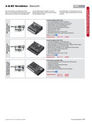
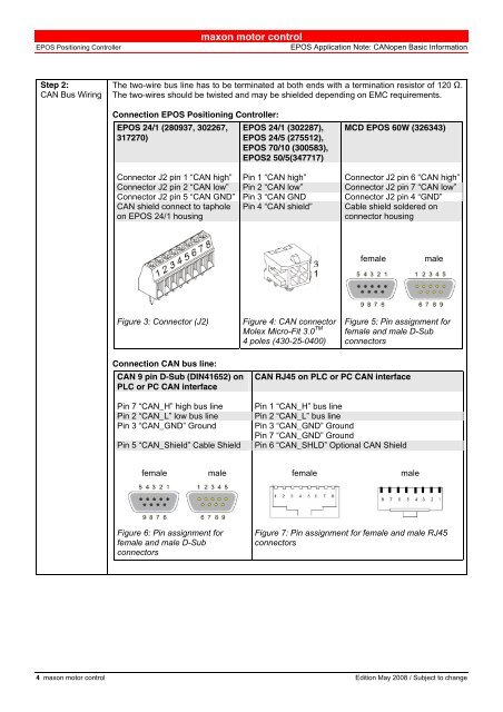
Step 2:<br />
CAN Bus Wiring<br />
The two-wire bus line has to be terminated at both ends with a termination resistor of 120 Ω.<br />
The two-wires should be twisted and may be shielded depending on EMC requirements.<br />
Connection <strong>EPOS</strong> Positioning Controller:<br />
<strong>EPOS</strong> 24/1 (280937, 302267,<br />
317270)<br />
<strong>EPOS</strong> 24/1 (302287),<br />
<strong>EPOS</strong> 24/5 (275512),<br />
<strong>EPOS</strong> 70/10 (300583),<br />
<strong>EPOS</strong>2 50/5(347717)<br />
MCD <strong>EPOS</strong> 60W (326343)<br />
Connector J2 pin 1 “CAN high” Pin 1 “CAN high” Connector J2 pin 6 “CAN high”<br />
Connector J2 pin 2 “CAN low” Pin 2 “CAN low” Connector J2 pin 7 “CAN low”<br />
Connector J2 pin 5 “CAN GND” Pin 3 “CAN GND Connector J2 pin 4 “GND”<br />
CAN shield connect to taphole<br />
on <strong>EPOS</strong> 24/1 housing<br />
Pin 4 “CAN shield”<br />
Cable shield soldered on<br />
connector housing<br />
female<br />
male<br />
Figure 3: Connector (J2)<br />
Figure 4: CAN connector<br />
Molex Micro-Fit 3.0 TM<br />
4 poles (430-25-0400)<br />
Figure 5: Pin assignment for<br />
female and male D-Sub<br />
connectors<br />
Connection CAN bus line:<br />
CAN 9 pin D-Sub (DIN41652) on<br />
PLC or PC CAN interface<br />
Pin 7 “CAN_H” high bus line<br />
Pin 2 “CAN_L” low bus line<br />
Pin 3 “CAN_GND” Ground<br />
Pin 5 “CAN_Shield” Cable Shield<br />
CAN RJ45 on PLC or PC CAN interface<br />
Pin 1 “CAN_H” bus line<br />
Pin 2 “CAN_L” bus line<br />
Pin 3 “CAN_GND” Ground<br />
Pin 7 “CAN_GND” Ground<br />
Pin 6 “CAN_SHLD” Optional CAN Shield<br />
female male female male<br />
Figure 6: Pin assignment for<br />
female and male D-Sub<br />
connectors<br />
Figure 7: Pin assignment for female and male RJ45<br />
connectors<br />
4 maxon motor control Edition May 2008 / Subject to change