EPOS Application Note: Master Encoder Mode - Maxon Motor ag
EPOS Application Note: Master Encoder Mode - Maxon Motor ag
EPOS Application Note: Master Encoder Mode - Maxon Motor ag

Create successful ePaper yourself
Turn your PDF publications into a flip-book with our unique Google optimized e-Paper software.
maxon motor control<br />
<strong>EPOS</strong> <strong>Application</strong> <strong>Note</strong>: <strong>Master</strong> <strong>Encoder</strong> <strong>Mode</strong> Edition December 2008<br />
<br />
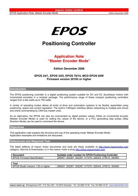
Positioning Controller<br />
<strong>Application</strong> <strong>Note</strong><br />
"<strong>Master</strong> <strong>Encoder</strong> <strong>Mode</strong>"<br />
Edition December 2008<br />
<strong>EPOS</strong> 24/1, <strong>EPOS</strong> 24/5, <strong>EPOS</strong> 70/10, MCD <strong>EPOS</strong> 60W<br />
Firmware version 2010h or higher<br />
Introduction<br />
The <strong>EPOS</strong> positioning controller is a digital positioning system suitable for DC and EC (brushless) motors with<br />
incremental encoders in a modular pack<strong>ag</strong>e. The performance range of these compact positioning controllers<br />
ranges from a few watts up to 700 watts.<br />
A variety of operating modes allows all kinds of drive and automation systems to be flexibly assembled using<br />
positioning, speed and current regulation. The built-in CANopen interface allows networking to multiple axis drives<br />
and online commanding by CAN bus master units.<br />
As an alternative, the <strong>EPOS</strong> can also be commanded by digital position values. Either an incremental encoder<br />
(<strong>Master</strong> <strong>Encoder</strong> <strong>Mode</strong>) is used for setting the values of the device, or a PLC generating step pulses (Step<br />
Direction <strong>Mode</strong>) can be used to command the device.<br />
Objectives<br />
This application note explains the structure and use of the operating mode ‘<strong>Master</strong> <strong>Encoder</strong> <strong>Mode</strong>’.<br />
<strong>Application</strong> examples and limitations are discussed.<br />
References and Required Tool<br />
The latest editions of maxon motor documents and tools are freely available at http://www.maxonmotor.com<br />
category «Service & Downloads» or in the maxon motor e-shop http://shop.maxonmotor.com.<br />
Document<br />
Suitable order number for <strong>EPOS</strong> Positioning Controller<br />
<strong>EPOS</strong> Firmware Specification 280937, 302267, 302287, 317270, 326343, 275512, 300583<br />
Tool<br />
<strong>EPOS</strong> Studio Version 1.30 or higher 280937, 302267, 302287, 317270, 326343, 275512, 300583<br />
maxon motor <strong>ag</strong> Brünigstrasse 220 P.O. Box 263 CH-6072 Sachseln Tel.: 041/666 15 00 Fax: 041/666 16 50 www.maxonmotor.com
<strong>EPOS</strong> Positioning Controller<br />
maxon motor control<br />
<strong>EPOS</strong> <strong>Application</strong> <strong>Note</strong>: <strong>Master</strong> <strong>Encoder</strong> <strong>Mode</strong><br />
<strong>Master</strong> <strong>Encoder</strong> <strong>Mode</strong><br />
System Structure<br />
Figure 1: System Structure<br />
Quadrature Counter<br />
<strong>EPOS</strong> 24/1, <strong>EPOS</strong> 24/5<br />
Channel A Digital Input 3<br />
Channel B Digital Input 2<br />
Desired Value (Polarity = 0)<br />
Figure 2: Quadrature Counter<br />
<strong>EPOS</strong> 24/1 <strong>EPOS</strong> 24/5<br />
Input Volt<strong>ag</strong>e 0 … 24 VDC 0 … 24 VDC<br />
Max. Input Volt<strong>ag</strong>e -30 … + 30 VDC -30 … + 30 VDC<br />
Logic 0 < 0.7 VDC < 1.5 VDC<br />
Logic 1 > 2.4 VDC > 3.0 VDC<br />
Max. Input Frequency 500 kHz 100 kHz<br />
<strong>EPOS</strong> 70/10, MCD <strong>EPOS</strong> 60W<br />
Channel A Digital Input 8<br />
Channel B Digital Input 7<br />
Channel A/ Digital Input 8/<br />
Channel B/ Digital Input 7/<br />
Desired Value (Polarity = 0)<br />
Figure 3: Quadrature Counter<br />
<strong>EPOS</strong> 70/10<br />
MCD <strong>EPOS</strong> 60W<br />
Input Volt<strong>ag</strong>e 0 … 5 VDC 0 … 5 VDC<br />
Max. Input Volt<strong>ag</strong>e -24 … + 24 VDC -24 … + 24 VDC<br />
Logic 0 < 2.0 VDC < 2.0 VDC<br />
Logic 1 > 3.0 VDC > 3.0 VDC<br />
Max. Input Frequency 1 MHz 500 kHz<br />
2 maxon motor control Edition December 2008 / Subject to change
<strong>EPOS</strong> <strong>Application</strong> <strong>Note</strong>: <strong>Master</strong> <strong>Encoder</strong> <strong>Mode</strong><br />
maxon motor control<br />
<strong>EPOS</strong> Positioning Controller<br />
Parameter Input<br />
Name Index Sub-index Description<br />
Digital Position Scaling Numerator 0x2300 0x02 Numerator of the scaling factor. Can be used for<br />
electronic gearing.<br />
Digital Position Scaling Denominator 0x2300 0x03 Denominator of the scaling factor. Can be used<br />
for electronic gearing.<br />
Digital Position Polarity 0x2300 0x04 Polarity of the quadrature counter. The direction<br />
can be changed.<br />
(0 = Positive; 1 = Negative)<br />
Minimum Position Limit 0x607D 0x01 Defines the negative position limit for the<br />
position demand value.<br />
Maximum Position Limit 0x607D 0x02 Defines the positive position limit for the position<br />
demand value.<br />
Parameter Output<br />
Name Index Sub-index Description<br />
Digital Position Desired Value 0x2300 0x01 Counter value of the quadrature counter. This<br />
value is the base for the scaling and limiting<br />
functions.<br />
Position Demand Value 0x6062 0x00 Output of the master encoder mode after scaling<br />
and limiting. This is the setting value for the<br />
position regulator.<br />
<strong>Note</strong>s:<br />
- For a better behaviour use a scaling factor ≤ 1. In fact that no interpolation is implemented,<br />
movements with factors >> 1 result in bigger position jumps which produces current peaks.<br />
- Switch off the software position limitation, setting the values of maximum and minimum position limit<br />
to INT32_MAX resp. INT32_MIN!<br />
Edition December 2008 / Subject to change maxon motor control 3
<strong>EPOS</strong> Positioning Controller<br />
maxon motor control<br />
<strong>EPOS</strong> <strong>Application</strong> <strong>Note</strong>: <strong>Master</strong> <strong>Encoder</strong> <strong>Mode</strong><br />
Configuration<br />
Step 1:<br />
System Configuration<br />
Step 2:<br />
Regulation Tuning<br />
Do the standard system configuration using the <strong>EPOS</strong> Studio and the Startup Wizard.<br />
(Document ‘Getting Started’)<br />
Topics:<br />
- Minimum External Wiring<br />
- RS232 Communication Setting<br />
- <strong>Motor</strong> Type<br />
- <strong>Motor</strong> Pole Pair<br />
- <strong>Motor</strong> Data<br />
- Position Sensor Type<br />
- Position Resolution<br />
Using the ‘Step Direction’ mode the current regulator and the position regulator have to<br />
be tuned. The speed regulator is not used. (see document ‘Getting Started’).<br />
<strong>Note</strong>s:<br />
For testing the behaviour of the regulators use the Profile Position<br />
<strong>Mode</strong>! Only for small steps use the Position <strong>Mode</strong>!<br />
Current Regulator (Current Step)<br />
Position Regulator (Profile Position Step)<br />
Step 3:<br />
I/O Configuration and<br />
Wiring<br />
Do the wiring for the step direction mode. All used digital inputs or outputs have to be<br />
configured for the correct purpose. Use the I/O Configuration Wizard!<br />
<strong>EPOS</strong> 24/1, <strong>EPOS</strong> 24/5 <strong>Master</strong> <strong>Encoder</strong> Channel A -> Digital Input 3<br />
<strong>Master</strong> <strong>Encoder</strong> Channel B -> Digital Input 2<br />
<strong>EPOS</strong> 70/10,<br />
<strong>Master</strong> <strong>Encoder</strong> Channel A -> Digital Input 8, 8/<br />
MCD <strong>EPOS</strong> 60 W <strong>Master</strong> <strong>Encoder</strong> Channel B -> Digital Input 7, 7/<br />
Digital Input 2 or 7<br />
-> General Purpose A<br />
Digital Input 3 or 8<br />
-> General Purpose B<br />
Any free digital input -> Enable (optional) *<br />
Any free digital output -> Ready (optional) **<br />
Step 4:<br />
<strong>Master</strong> <strong>Encoder</strong> <strong>Mode</strong><br />
Activate and configure the master encoder mode. Use the tool <strong>EPOS</strong> Studio.<br />
Step 5:<br />
Save All Parameters<br />
Execute the menu item ‘Save All Parameter’ in the context menu from the used node<br />
(<strong>EPOS</strong> Studio – Navigation Window Workspace or Communication).<br />
* In order to clear the fault condition the device must be reset. Set the 'Enable' input from inactive to active.<br />
* The ‘Ready’ output can be used to report a fault condition.<br />
4 maxon motor control Edition December 2008 / Subject to change
<strong>EPOS</strong> <strong>Application</strong> <strong>Note</strong>: <strong>Master</strong> <strong>Encoder</strong> <strong>Mode</strong><br />
maxon motor control<br />
<strong>EPOS</strong> Positioning Controller<br />
<strong>Application</strong> Example ‘Dual Axis System’<br />
A typical application for the master encoder mode is a dual axis system. The master axis is configured, enabled<br />
and commanded via the serial interface (RS232 or CAN bus) and is working in the ‘Profile Position’ or ‘Profile<br />
Velocity’ mode. The slave axis is working in the ‘<strong>Master</strong> <strong>Encoder</strong>’ mode. The CAN bus interface is only used for<br />
configuration, monitoring and enabling. The set values for the slave axis are calculated using the encoder signals<br />
of the master axis.<br />
Figure 4: <strong>Application</strong> Example ‘Dual Axis System’<br />
* <strong>Note</strong>: To reach optimal signal conditions, use an external line receiver for <strong>EPOS</strong> 24/1 and <strong>EPOS</strong> 24/5!<br />
Calculation Velocity Slave Axis<br />
The velocity of the slave axis is not only defined by the scaling factor, but also by the ratio of the encoder resolution<br />
of the master and slave axis.<br />
Velocity<br />
SlaveAxis<br />
[rpm] = Velocity<br />
<strong>Master</strong>Axis<br />
EncRes<br />
[rpm] ⋅<br />
EncRes<br />
<strong>Master</strong>Axis<br />
SlaveAxis<br />
[pulse/turn]<br />
ScalingNumerator<br />
⋅ Polarity[1, −1]<br />
⋅<br />
[pulse/turn]<br />
ScalingDenominator<br />
SlaveAxis<br />
SlaveAxis<br />
Figure 5: Calculation Velocity Slave Axis / <strong>Master</strong> <strong>Encoder</strong> <strong>Mode</strong><br />
Edition December 2008 / Subject to change maxon motor control 5
<strong>EPOS</strong> Positioning Controller<br />
maxon motor control<br />
<strong>EPOS</strong> <strong>Application</strong> <strong>Note</strong>: <strong>Master</strong> <strong>Encoder</strong> <strong>Mode</strong><br />
Limiting Factors<br />
The main limiting factor is the input frequency of the encoder signals.<br />
Max. Input Frequency<br />
Slave Axis<br />
<strong>Encoder</strong><br />
<strong>Master</strong> Axis<br />
Max. Velocity (Scaling Factor 1)<br />
<strong>Master</strong> Axis<br />
<strong>EPOS</strong> 24/1 500 kHz > 25’000 rpm (no limitations)<br />
<strong>EPOS</strong> 24/5 100 kHz 12’000 rpm<br />
500 pulse/turn<br />
<strong>EPOS</strong> 70/10 1 MHz > 25’000 rpm (no limitations)<br />
MCD <strong>EPOS</strong> 60W 500 kHz<br />
> 25’000 rpm (no limitations)<br />
<strong>EPOS</strong> 24/1 500 kHz > 25’000 rpm (no limitations)<br />
<strong>EPOS</strong> 24/5 100 kHz 6’000 rpm<br />
1000 pulse/turn<br />
<strong>EPOS</strong> 70/10 1 MHz > 25’000 rpm (no limitations)<br />
MCD <strong>EPOS</strong> 60W 500 kHz<br />
> 25’000 rpm (no limitations)<br />
<strong>EPOS</strong> 24/1 500 kHz 6’000 rpm<br />
<strong>EPOS</strong> 24/5 100 kHz 1’200 rpm<br />
5000 pulse/turn<br />
<strong>EPOS</strong> 70/10 1 MHz 12’000 rpm<br />
MCD <strong>EPOS</strong> 60W 500 kHz<br />
6’000 rpm<br />
Figure 6: Limiting Factors / <strong>Master</strong> <strong>Encoder</strong> <strong>Mode</strong><br />
<strong>Note</strong>:<br />
Higher velocities of the slave axis can be reached by increasing the scaling factor > 1 (Consider<br />
restriction notes on p<strong>ag</strong>e 3).<br />
Axis Synchronisation<br />
Synchronisation works only in one direction: from the master to the slave. The opposite direction (from the slave to<br />
the master) can not be synchronized. This means that a following error of the master axis can be corrected, but a<br />
following error of the slave axis can not be corrected.<br />
6 maxon motor control Edition December 2008 / Subject to change