Development of a 500-kV DC XLPE Cable System
Development of a 500-kV DC XLPE Cable System
Development of a 500-kV DC XLPE Cable System

Create successful ePaper yourself
Turn your PDF publications into a flip-book with our unique Google optimized e-Paper software.
<strong>Development</strong> <strong>of</strong> a <strong>500</strong>-<strong>kV</strong> <strong>DC</strong> <strong>XLPE</strong> <strong>Cable</strong> <strong>System</strong><br />
<br />
<br />
<br />
<br />
<br />
<br />
<br />
<br />
<br />
<br />
<br />
<br />
<br />
<br />
<br />
<br />
<br />
<br />
<br />
<br />
<br />
<br />
<br />
<br />
<br />
<br />
<br />
<br />
<br />
<br />
<br />
<br />
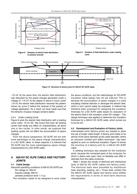
Figure 8<br />
Variation <strong>of</strong> electric field distribution<br />
in polarity reversal.<br />
Figure 9<br />
Variation <strong>of</strong> field distribution under loading<br />
cycle.<br />
<br />
<br />
<br />
<br />
<br />
<br />
<br />
<br />
<br />
Figure 10 Structure <strong>of</strong> factory joint for <strong>500</strong>-<strong>kV</strong> <strong>DC</strong> <strong>XLPE</strong> cable.<br />
-75 <strong>kV</strong>. At the same time, the electric field distribution<br />
was disturbed by the space charges generated under a<br />
voltage <strong>of</strong> +75 <strong>kV</strong>. At the elapse <strong>of</strong> about 5 hours under<br />
-75 <strong>kV</strong>, the electric field distribution resumed the pattern<br />
shown by curve C before the reversal <strong>of</strong> the polarity <strong>of</strong><br />
voltage application. As a result, we have made sure that<br />
the behavior <strong>of</strong> space charges remains stable.<br />
3.3.4 Under Loading Cycle<br />
Figure 9 plots the electric field distribution with a loading<br />
cycle under -75 <strong>kV</strong> <strong>DC</strong>. We found that even 30 loading<br />
cycles had hardly any effect on characteristics, let alone<br />
one or two cycles. In other words, we suppose that<br />
loading cycles will not affect the accumulation <strong>of</strong> space<br />
charges.<br />
From the above perspective, <strong>DC</strong>-<strong>XLPE</strong> will act with<br />
more advantage on the space charge characteristics<br />
in a <strong>DC</strong> <strong>XLPE</strong> cable. In these respects it is inferred that<br />
<strong>DC</strong>-<strong>XLPE</strong> has the more advantageous space charge<br />
characteristics for a <strong>DC</strong> <strong>XLPE</strong> cable.<br />
4. <strong>500</strong>-KV <strong>DC</strong> <strong>XLPE</strong> CABLE AND FACTORY<br />
JOINTS<br />
4.1 <strong>Cable</strong> Design<br />
Assumed operating conditions <strong>of</strong> <strong>500</strong>-<strong>kV</strong> <strong>DC</strong>-<strong>XLPE</strong> are:<br />
<strong>DC</strong> voltage U 0: <strong>500</strong> <strong>kV</strong><br />
Impulse voltage: 850 <strong>kV</strong><br />
(arrester protection level: 1.7 U 0)<br />
The insulation needs to be designed to work under<br />
the above conditions, but the methodology for <strong>DC</strong>-<strong>XLPE</strong><br />
insulation cable design has not yet matured. This is<br />
because the accumulation <strong>of</strong> space charges in a solid<br />
insulating material disturbs or deranges the electric field,<br />
which in turn cannot easily be evaluated. A method has<br />
therefore been proposed for designing the insulation<br />
thickness for a <strong>DC</strong> <strong>XLPE</strong> cable based on evaluation <strong>of</strong><br />
the electric field in the insulation under <strong>DC</strong> voltage 7) . This<br />
design technique was applied to determine the insulation<br />
thickness for a <strong>500</strong>-<strong>kV</strong> <strong>DC</strong> <strong>XLPE</strong> cable, which turned out<br />
to be 23 mm.<br />
4.2 <strong>Development</strong> and Evaluation <strong>of</strong> Factory Joints<br />
Intermediate joints (factory joints) are needed to allow<br />
the use <strong>of</strong> longer cable length. A factory joint needs to be<br />
almost <strong>of</strong> the same diameter as the cable diameter, where<br />
an extrusion molded joint (EMJ) technique 8) has been<br />
applied to work on reinforced insulation. Figure 10 shows<br />
the structure <strong>of</strong> a factory joint for a <strong>500</strong>-<strong>kV</strong> <strong>DC</strong> <strong>XLPE</strong><br />
cable.<br />
A welding technique was adopted for the conductor<br />
joints, because the connected parts <strong>of</strong> the conductor, for<br />
which a sleeve was used, have no flexibility and differ in<br />
diameter from the cable conductor.<br />
Table 1 shows the results <strong>of</strong> electrical and mechanical<br />
tests <strong>of</strong> <strong>500</strong>-<strong>kV</strong> <strong>DC</strong> <strong>XLPE</strong> cables and factory joints.<br />
The electrical tests were preceded by mechanical<br />
tests (bending, twisting, etc.). Those tests verified that<br />
the <strong>500</strong>-<strong>kV</strong> <strong>DC</strong> <strong>XLPE</strong> cables and factory joints fulfilled<br />
the requirements in terms <strong>of</strong> short-term electrical<br />
characteristics.<br />
Furukawa Review, No. 25 2004 50