Development of a Variable Optical Attenuator
Development of a Variable Optical Attenuator
Development of a Variable Optical Attenuator

You also want an ePaper? Increase the reach of your titles
YUMPU automatically turns print PDFs into web optimized ePapers that Google loves.
<strong>Development</strong> <strong>of</strong> a <strong>Variable</strong> <strong>Optical</strong> <strong>Attenuator</strong><br />
by Kouki Sato *, Takuma Aoki *, Yasuhiro Watanabe *, Yuichiro Oguri *,<br />
Nobuyuki Shibata * 2 , Toshimitsu Nishiwaki * 2 , Mizuki Oike * 2<br />
and Toshihiko Ota * 3<br />
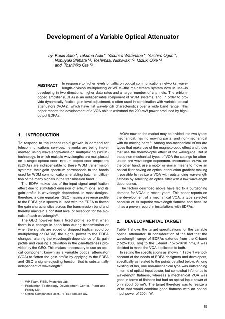
In response to higher levels <strong>of</strong> traffic on optical communications networks, wavelength-division<br />
multiplexing or WDM--the mainstream system now in use--is<br />
ABSTRACT<br />
developing in two directions: higher data rates and a larger number <strong>of</strong> channels. The erbiumdoped<br />
amplifier (EDFA) is an indispensable component <strong>of</strong> WDM systems, and, in order to provide<br />
dynamically flexible gain level adjustment, is <strong>of</strong>ten used in combination with variable optical<br />
attenuators (VOAs), which have flat wavelength characteristics over a wide band range. This<br />
paper reports the development <strong>of</strong> a VOA able to withstand the 200-mW power produced by highoutput<br />
EDFAs.<br />
1. INTRODUCTION<br />
To respond to the recent rapid growth in demand for<br />
telecommunications services, networks are being implemented<br />
using wavelength-division multiplexing (WDM)<br />
technology, in which multiple wavelengths are multiplexed<br />
on a single optical fiber. Erbium-doped fiber amplifiers<br />
(EDFAs) are indispensable to these WDM transmission<br />
systems: their gain spectrum corresponds to the bands<br />
used for WDM communications, enabling batch amplification<br />
<strong>of</strong> the many signals in the transmission band.<br />
The EDFA makes use <strong>of</strong> the input signal amplification<br />
effect due to stimulated emission <strong>of</strong> erbium ions, and its<br />
gain pr<strong>of</strong>ile is wavelength dependent. In most designs,<br />
therefore, a gain equalizer (GEQ) having a reverse pr<strong>of</strong>ile<br />
to the EDFA gain spectra is used with the EDFA to flatten<br />
the gain characteristics across the transmission band and<br />
thereby maintain a constant level <strong>of</strong> reception for the signals<br />
<strong>of</strong> each wavelength 1) .<br />
The GEQ however has a fixed pr<strong>of</strong>ile, so that when<br />
there is a change in span loss during transmission or<br />
when the signals are added or dropped (optical add-drop<br />
multiplexing or OADM) the signal power to the EDFA<br />
changes, altering the wavelength-dependence <strong>of</strong> its gain<br />
pr<strong>of</strong>ile and causing a deviation in the gain-flatteness provided<br />
by the GEQ. This makes it necessary to use an optical<br />
component known as a variable optical attenuator<br />
(VOA) to flatten the gain pr<strong>of</strong>ile by applying to the EDFA<br />
and GEQ a signal-adjusting function that is substantially<br />
independent <strong>of</strong> wavelength 2) .<br />
* WP Team, FITEL Photonics Lab.<br />
* 2 Production Technology <strong>Development</strong> Center, Plant and<br />
Facility Div.<br />
* 3 <strong>Optical</strong> Components Dept., FITEL Products Div.<br />
VOAs now on the market may be divided into two types:<br />
mechanical, having moving parts, and non-mechanical<br />
with no moving parts 3) . Among non-mechanical VOAs are<br />
types that make use <strong>of</strong> the magneto-optic effect and those<br />
that use the thermo-optic effect <strong>of</strong> the waveguide. But in<br />
these non-mechanical types <strong>of</strong> VOA the settings for attenuation<br />
are wavelength-dependent. Mechanical VOAs, on<br />
the other hand, use a motor or similar means to move an<br />
optical filter having an optical attenuation gradient making<br />
it possible to realize a VOA with outstanding wavelength<br />
flatness by selecting an optical filter with a low wavelength<br />
dependence.<br />
The factors described above have led to a burgeoning<br />
demand for VOAs in recent years. This paper reports on<br />
the development <strong>of</strong> a mechanical VOA, a type selected<br />
because <strong>of</strong> its superior wavelength flatness and because<br />
it has a proven record in installations with EDFAs.<br />
2. DEVELOPMENTAL TARGET<br />
Table 1 shows the target specifications for the variable<br />
optical attenuator. In consideration <strong>of</strong> the fact that the<br />
wavelength range <strong>of</strong> EDFAs extends from the C-band<br />
(1525-1560 nm) to the L-band (1575-1610 nm), it was<br />
decided to make the VOA applicable to both.<br />
In setting the specifications as shown in Table 1 we took<br />
account <strong>of</strong> the needs <strong>of</strong> EDFA designers and developers,<br />
specifically as related to the points detailed below. Among<br />
existing VOAs, one non-mechanical type was outstanding<br />
in terms <strong>of</strong> optical input power, but somewhat inferior as to<br />
wavelength flatness, whereas a mechanical VOA was<br />
good in terms <strong>of</strong> flatness but had an optical input power <strong>of</strong><br />
only about 50 mW. The target therefore was to realize a<br />
VOA that would combine good flatness with an optical<br />
input power <strong>of</strong> 200 mW.<br />
15
The term "repeatability" in Table 1 denotes the setting<br />
accuracy for attenuation when resetting the voltage<br />
detected by the potentiometer or the number <strong>of</strong> pulses<br />
applied to the stepping motor, and "backlash" denotes the<br />
attenuation setting accuracy under the above conditions<br />
when settings have been made including reversing the<br />
direction <strong>of</strong> motor operation.<br />
3. STRUCTURE OF THE VOA<br />
Let us describe the structure <strong>of</strong> the VOA that was developed<br />
through this research by following along the light<br />
path. The input and output fibers are single-mode fibers<br />
(SMFs). The ferrules at the fiber ends are angled-polished<br />
at 6° and an anti-reflection (AR) coating is applied. Beam<br />
diameter is expanded by a lens and the distance between<br />
the lens and the ferrule is adjusted so that the coupling<br />
efficiency is maximized at the operating distance. No<br />
adhesive was used in the light path <strong>of</strong> the VOA, and this<br />
was essential to improving optical input power performance.<br />
The light beam from the input lens was reflected<br />
180° by a prism, in order that the input and output fibers<br />
would be arranged on the same side <strong>of</strong> the VOA module,<br />
with consequent savings <strong>of</strong> space. From the prism the<br />
light beam passes through an optical filter (attenuator element)<br />
having an optical density gradient in the direction <strong>of</strong><br />
filter travel, and is then focused by a lens at the output<br />
SMF.<br />
Among attenuator elements, filters with a low level <strong>of</strong><br />
wavelength dependence are referred to as neutral density<br />
(ND) filters. The ND filter is connected by means <strong>of</strong> a plastic<br />
nut to the stepping motor, and regulates attenuation by<br />
a reciprocating movement in the direction <strong>of</strong> the density<br />
gradient, driven by a tap formed on the nut and by a screw<br />
rotated by the stepping motor. To suppress return loss, it<br />
is mounted at an angle to the light path.<br />
A potentiometer is provided to detect attenuation. A<br />
brush mounted on the nut detects resistance values by<br />
establishing contact with a resistance film. These values<br />
yield the filter position and thereby the corresponding<br />
attenuation. Settings for the attenuation <strong>of</strong> the VOA<br />
installed in the EDFA are controlled by feedback from<br />
EDFA output based on the pre-measured relationship<br />
between potentiometer resistance and attenuation.<br />
External interfaces for power supply to the stepping<br />
motor and potentiometer, and for reading <strong>of</strong> the resistance<br />
values are provided via a flexible circuit board by means<br />
<strong>of</strong> pin electrodes formed on the bottom panel <strong>of</strong> the VOA.<br />
To maintain the performance <strong>of</strong> moving components<br />
such as the stepping motor and brush <strong>of</strong> the potentiometer<br />
and electrical contacts on the circuit board, the VOA<br />
module package is filled with nitrogen gas and hermetically<br />
sealed by welding.<br />
4. PROTOTYPE<br />
Photo 1 shows the VOA developed in this work. The target<br />
dimensions <strong>of</strong> 30 mm width, 50 mm length (30 mm<br />
length for the fiber-protective sleeve) and 11 mm height<br />
were achieved.<br />
4.1 <strong>Optical</strong> Characteristics<br />
4.1.1 Insertion loss<br />
Figure 1 is a histogram <strong>of</strong> VOA insertion loss. Using a<br />
1.55-µm light source, average insertion loss is 0.28 dB<br />
with a standard deviation <strong>of</strong> 0.09 dB. This corresponds to<br />
Table 1<br />
VOA target specifications<br />
<strong>Optical</strong> characteristics<br />
Wavelength range<br />
Insertion loss<br />
Return loss<br />
Wavelength flatness<br />
1525-1610 nm<br />
45 dB<br />
0.2 dB or 1% <strong>of</strong> attenuation,<br />
whichever is greater<br />
the loss between collimators, and the loss in the prism<br />
(including AR coating) and that part <strong>of</strong> the ND filter that is<br />
not coated with metallic film. It can be seen that the<br />
results obtained from the prototype fully satisfy the developmental<br />
target <strong>of</strong> 0.6 dB.<br />
4.1.2 Return loss<br />
Figure 2 shows the dependence <strong>of</strong> return loss on motor<br />
stepping count at the input and output ports measured for<br />
a 1.55-µm light source. This result shows the return loss<br />
measured for the entire attenuation range--that is to say<br />
for attenuation loss measured while changing motor stepping<br />
count. It can be seen that the developmental target <strong>of</strong><br />
45 dB or more was attained for the whole <strong>of</strong> the attenuation<br />
range.<br />
Figure 3 shows a histogram <strong>of</strong> VOA return loss for the<br />
input and output ports. In Figure 3 the values taken for<br />
return loss for the VOA module are the worst values in the<br />
whole attenuation range. The values obtained for average<br />
return loss were 48.3 dB at the input port with a standard<br />
deviation <strong>of</strong> 2.2 dB, and 49.1 dB at the output port with a<br />
standard deviation <strong>of</strong> 1.8 dB.<br />
4.1.3 Wavelength characteristics<br />
Figure 4 shows the wavelength dependence <strong>of</strong> the attenuation<br />
spectra. This represents the developmental target. It<br />
was confirmed that flatness (maximum attenuation minus<br />
minimum) was held to 0.2 dB or less for all ranges <strong>of</strong><br />
attenuation in the C or L bands, and to 0.3 dB or less for<br />
the range covering both C and L bands. Neither were any<br />
periodic ripples observed in these spectra, clearly showing<br />
that no multiple interference occurred within the ND filter<br />
or other optical components. Specifically, defining a ripple<br />
as the difference between maximum and minimum attenuation<br />
in any 2-nm band at wavelengths <strong>of</strong> from 1520 to<br />
1620 nm, the average ripple value was 0.032 dB.<br />
4.1.4 Polarization-dependent loss<br />
Figure 5 shows the dependence <strong>of</strong> polarization-dependent<br />
loss (PDL) on motor stepping count. It can be seen that<br />
the developmental target <strong>of</strong> 0.15 dB or less was achieved<br />
for the whole <strong>of</strong> the attenuation range (corresponding to<br />
motor stepping count). The wavelength-dependence <strong>of</strong><br />
PDL was also measured for the C and L bands (no graph<br />
shown), and it was confirmed that there was no significant<br />
wavelength dependence, and the target value <strong>of</strong> 0.15 dB<br />
was satisfied.<br />
4.1.5 Temperature dependence<br />
Figure 6 is a histogram <strong>of</strong> the temperature dependence <strong>of</strong><br />
insertion loss from -5 to +70°C. The average value was<br />
0.10 dB with a standard deviation <strong>of</strong> 0.05 dB. It can be<br />
seen that the target <strong>of</strong> 0.15 dB or less was comfortably<br />
achieved. Temperature dependence is believed to be<br />
impacted by the method by which the prism is immobilized,<br />
and the good results obtained are attributed to the<br />
care taken regarding the amount <strong>of</strong> epoxy adhesive used,<br />
and the position and area to which the adhesive was<br />
applied.<br />
60<br />
0<br />
Return loss (dB)<br />
55<br />
50<br />
45<br />
Attenuation (dB)<br />
-5<br />
-10<br />
-15<br />
Input port<br />
Output port<br />
40<br />
0 100 200 300 400 500 600 700<br />
Motor stepping count<br />
-20<br />
1520 1540 1560 1580 1600 1620<br />
Wavelength (nm)<br />
Figure 2<br />
Dependence <strong>of</strong> return loss on motor stepping count<br />
Figure 4<br />
Wavelength dependence <strong>of</strong> attenuation spectra<br />
20<br />
0.30<br />
Frequency<br />
15<br />
10<br />
5<br />
Input port<br />
Output port<br />
PDL<br />
0.25<br />
0.20<br />
0.15<br />
0.10<br />
0.05<br />
0<br />
~40 ~45 ~50 ~55 ~60<br />
Return loss (dB)<br />
0.00<br />
0 100 200 300 400 500 600 700<br />
Motor stepping count<br />
Figure 3<br />
Histogram <strong>of</strong> VOA return loss<br />
Figure 5<br />
Dependence <strong>of</strong> PDL on motor stepping count<br />
17
14<br />
70<br />
Frequency<br />
12<br />
10<br />
8<br />
6<br />
4<br />
2<br />
Temperature (°C)<br />
60<br />
50<br />
40<br />
30<br />
ND filter<br />
VOA Module<br />
Figure 6<br />
0<br />
~0.05 ~0.10 ~0.15 ~0.20 ~0.25<br />
Temperature dependence <strong>of</strong> insertion loss (dB)<br />
Histogram <strong>of</strong> temperature dependence <strong>of</strong> insertion<br />
loss<br />
20<br />
0 5 10 15 20 25<br />
Time (hr)<br />
Figure 8 Temperature <strong>of</strong> ND filter and VOA module<br />
Change in attenuation (dB)<br />
0.60<br />
0.40<br />
0.20<br />
0.00<br />
-0.20<br />
-0.40<br />
500 mW 200 mW 50 mW<br />
Attenuation (dB)<br />
20<br />
15<br />
10<br />
5<br />
-0.60<br />
0 100 200 300 400 500<br />
Time (hr)<br />
0<br />
0.0 1.0 2.0 3.0 4.0<br />
Potentiometer voltage (V)<br />
Figure 7<br />
Results <strong>of</strong> high-power optical input power test <strong>of</strong><br />
VOA<br />
Figure 9<br />
Relationship between potentiometer voltage and<br />
attenuation<br />
4.1.6 Input power<br />
Figure 7 shows the results <strong>of</strong> a high-power optical input<br />
power test, in which changes in the attenuation <strong>of</strong> the<br />
VOA were measured as input power changed. As the figure<br />
shows, a steady drop in attenuation is seen when optical<br />
input power is 500 mW. This is thought to be due to<br />
the ND filter's losing its attenuation film function as a<br />
result <strong>of</strong> oxidation <strong>of</strong> the metals <strong>of</strong> which it is composed.<br />
The reason that the ND filter film becomes oxidized is<br />
thought to be absorption <strong>of</strong> the optical input power by the<br />
ND filter film resulting in a rise in film temperature. Thus to<br />
guarantee use at the target <strong>of</strong> 200 mW, we present in<br />
Figure 8 the results <strong>of</strong> measurements <strong>of</strong> ND filter and<br />
VOA module temperature at an optical input power <strong>of</strong> 300<br />
mW. It can be seen that ND filter temperature was approximately<br />
60°C and module temperature was about 40°C. It<br />
is therefore hypothesized that ND filter film oxidation at<br />
500 mW input is promoted by the rise in temperature due<br />
to the absorption <strong>of</strong> the optical input power by the ND filter<br />
film and its conversion into heat. From Figure 7, however,<br />
it can be seen that, despite the fact that at the target input<br />
<strong>of</strong> 200 mW there was some small increase in attenuation<br />
at the early stages <strong>of</strong> irradiation, which may be attributable<br />
to the temperature characteristics <strong>of</strong> the module itself, the<br />
oxidation <strong>of</strong> the ND filter film progressed extremely slowly<br />
so that no change over time in attenuation was measured.<br />
Further the temperature <strong>of</strong> the VOA module only rose to<br />
somewhat less than 40°C, confirming that operation under<br />
conditions <strong>of</strong> actual installation would present no problem.<br />
4.2 Operating Characteristics<br />
4.2.1 Attenuation setting accuracy<br />
Figure 9 shows the relationship between potentiometer<br />
voltage and attenuation (Note that the attenuation range<br />
for the ND filter installed in this VOA was 0 - 20 dB.)<br />
Attenuation does show some degree <strong>of</strong> departure from linearity<br />
in the vicinity <strong>of</strong> 5 dB, but when a single pulse was<br />
applied to the stepping motor in a direction such that<br />
attenuation was increased or decreased, the direction <strong>of</strong><br />
increase or decrease in the attenuation and the potentiometer<br />
voltage detected were in agreement, confirming<br />
that the VOA was functioning normally. The amount <strong>of</strong><br />
change in attenuation for each pulse applied to the stepping<br />
motor averaged 0.040 dB/step, comfortably realizing<br />
the target value <strong>of</strong> 0.1 dB/step.<br />
4.2.2 Repeatability and backlash<br />
The next item evaluated was the repeatability and backlash<br />
when a series <strong>of</strong> 100 pulses was applied to the stepping<br />
motor in both directions. The histogram in Figure 10<br />
shows the results. Repeatability was 0.011 dB with a standard<br />
deviation <strong>of</strong> 0.010 dB, and backlash was 0.041 dB<br />
with a standard deviation <strong>of</strong> 0.021 dB, achieving the target<br />
values in both cases.<br />
18 Furukawa Review, No. 20 2001
15<br />
0.08<br />
Repeatability<br />
Backlash<br />
Frequency<br />
10<br />
5<br />
Insertion loss (dB)<br />
0.04<br />
0.00<br />
-0.04<br />
0<br />
~0.02 ~0.04 ~0.06 ~0.08 ~0.10<br />
Repeatability/backlash (dB)<br />
-0.08<br />
0.40<br />
Insertion loss (dB)<br />
Figure 10 Histogram <strong>of</strong> repeatability and backlash<br />
0.08<br />
0.06<br />
0.04<br />
0.02<br />
0.00<br />
-0.02<br />
0.15<br />
Potentiometer voltage (%)<br />
0.20<br />
0.00<br />
-0.20<br />
-0.40<br />
A<br />
B<br />
Figure 12 Results <strong>of</strong> Bellcore environmental tests<br />
C<br />
A: Temperature-humidity aging<br />
B: Temperature-humidity cycling<br />
C: High temperature storage (dry)<br />
D: Low temperature storage<br />
E: High temperature storage (damp)<br />
D<br />
E<br />
Potentiometer voltage (%)<br />
0.10<br />
0.05<br />
0.00<br />
-0.05<br />
Vibration test<br />
Figure 11 Results <strong>of</strong> Bellcore mechanical tests<br />
5. RELIABILITY TESTING<br />
Mechanical shock test<br />
5.1 Bellcore Test<br />
The following presents the results <strong>of</strong> Bellcore tests (GR-<br />
1209 and 1221) conducted to test the reliability <strong>of</strong> the<br />
VOA module developed in this report.<br />
5.1.1 Mechanical tests<br />
Figure 11 shows the results <strong>of</strong> mechanical tests carried<br />
out on three modules each--for vibration (Bellcore 1209:<br />
10-55 Hz, amplitude 1.52 mm, 2 hours); and for mechanical<br />
shock (Bellcore 1221: 6-ft drop, 8 cycles x 5 times)--in<br />
terms <strong>of</strong> before-and-after change in insertion loss and<br />
change in voltage detected by the potentiometer (as a<br />
percentage <strong>of</strong> maximum voltage) when attenuation was<br />
set to insertion loss and maximum attenuation.<br />
After each <strong>of</strong> these mechanical tests there was virtually<br />
no change, either in insertion loss or potentiometer voltage,<br />
and the units tested were considered to have passed<br />
the Bellcore tests.<br />
5.1.2 Environmental tests<br />
Figure 12 shows the results <strong>of</strong> tests for environmental<br />
temperature and humidity that were carried out on three<br />
modules each--for temperature-humidity aging (Bellcore<br />
1209: 85°C, 85% RH, 14 days); for temperature-humidity<br />
cycling (Bellcore 1209: -40 to +75°C, 10-80% RH, 42<br />
cycles, 14 days); for high temperature storage (damp)<br />
(85°C, 85% RH, 2000 hours); for high temperature storage<br />
(dry) (85°C, 2000 hours); and for low temperature<br />
storage (-40°C, 2000 hours) (two modules only)--in terms<br />
<strong>of</strong> before-and-after change in insertion loss and change in<br />
voltage detected by the potentiometer (as a percentage <strong>of</strong><br />
maximum voltage) when attenuation was set to insertion<br />
loss and maximum attenuation. The results given for the<br />
high-temperature storage test and low-temperature storage<br />
tests are interim results at the 1000-hour stage, and<br />
the tests continue.<br />
After each <strong>of</strong> these environmental tests there was virtually<br />
no change, either in insertion loss or potentiometer<br />
voltage, and the units tested were considered to have<br />
passed the Bellcore tests.<br />
6. CONCLUSION<br />
A variable optical attenuator (VOA) has been developed<br />
that is primarily installed within an optical amplifier and is<br />
capable <strong>of</strong> controlling attenuation by means <strong>of</strong> external<br />
electrical signals that adjust dynamic variations in optical<br />
transmission path loss, <strong>of</strong>fers superior wavelength flat-<br />
19
ness and is capable <strong>of</strong> accepting high levels <strong>of</strong> power. It<br />
was confirmed that the following target values were satisfied:<br />
Wavelength range 1525-1610 nm<br />
Insertion loss<br />
45 dB<br />
Wavelength flatness