Recent Progress of High Power Semiconductor Lasers for EDFA ...
Recent Progress of High Power Semiconductor Lasers for EDFA ...
Recent Progress of High Power Semiconductor Lasers for EDFA ...

Create successful ePaper yourself
Turn your PDF publications into a flip-book with our unique Google optimized e-Paper software.
<strong>Recent</strong> <strong>Progress</strong> <strong>of</strong> <strong>High</strong> <strong>Power</strong> <strong>Semiconductor</strong> <strong>Lasers</strong><br />
<strong>for</strong> <strong>EDFA</strong> Pumping<br />
by Akihiko Kasukawa * , Toshikazu Mukaihara * , Takeharu Yamaguchi * and Jun'jiro Kikawa *<br />
Optical fiber communication systems using a WDM (wavelength division multiplexing)<br />
system are being introduced in long-haul networks to manage the explo-<br />
ABSTRACT<br />
sive increase in transmission capacity. Erbium-doped fiber amplifier (<strong>EDFA</strong>) is one <strong>of</strong> the key<br />
components to support WDM systems. <strong>High</strong> power lasers emitting at both 980 nm and 1480 nm<br />
are essential <strong>for</strong> pumping sources <strong>for</strong> <strong>EDFA</strong>. In this paper, state-<strong>of</strong>-the-art high power pumping<br />
lasers are reviewed. Furukawa Electric has succeeded to release high per<strong>for</strong>mance and high reliable<br />
pumping lasers. In particular, ultra-high output power <strong>of</strong> 250 mW-1480 nm modules have<br />
been commercialized. These high output power laser modules are <strong>of</strong> great importance <strong>for</strong> Raman<br />
amplifiers as well as <strong>EDFA</strong> applications.<br />
1. INTRODUCTION<br />
Optical fiber communication systems have realized large<br />
transmission capacity; however, bit rate increase utilizing<br />
traditional TDM (time division multiplexing) cannot manage<br />
the explosive demands <strong>for</strong> larger transmission capacity<br />
triggered by data communication and Internet. The<br />
urgent demands <strong>for</strong> larger transmission capacity have driven<br />
system planners to introduce WDM systems instead<br />
<strong>of</strong> TDM systems to make the best use <strong>of</strong> installed optical<br />
fibers.<br />
WDM systems are thought to be the most cost-effective<br />
way to handle the increasing transmission capacity using<br />
established transmission technologies. In WDM systems,<br />
which use multi-channel single frequency lasers such as<br />
distributed feedback lasers with slightly different wavelengths<br />
determined by ITU (International Telecommunication<br />
Union), total throughput transmission capacity can be<br />
increased by the number <strong>of</strong> lasers (channels).<br />
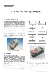
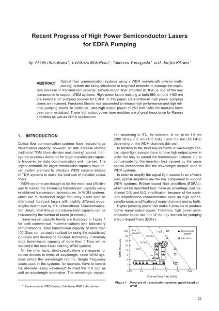
Transmission capacity trends are illustrated in Figure 1<br />
<strong>for</strong> both commercial implementations and laboratory<br />
demonstrations. Total transmission capacity <strong>of</strong> more than<br />
100 Gbps can be easily realized by using the established<br />
2.5-Gbps and developing 10-Gbps technology. Extremely<br />
large transmission capacity <strong>of</strong> more than 1 Tbps will be<br />
realized in the near future utilizing WDM systems.<br />
On the other hand, strict specifications are required <strong>for</strong><br />
optical devices in terms <strong>of</strong> wavelength, since WDM systems<br />
utilize the wavelength regime. Single frequency<br />
lasers used in the systems, <strong>for</strong> example, have to control<br />
the absolute lasing wavelength to meet the ITU grid as<br />
well as wavelength separation. The wavelength separation<br />
according to ITU, <strong>for</strong> example, is set to be 1.6 nm<br />
(200 GHz), 0.8 nm (100 GHz ) and 0.4 nm (50 GHz)<br />
depending on the WDM channels (bit rate).<br />
In addition to the strict requirements in wavelength control,<br />
signal light sources have to have high output power in<br />
order not only to extend the transmission distance but to<br />
compensate <strong>for</strong> the insertion loss caused by the many<br />
optical components like the wavelength coupler used in<br />
WDM systems.<br />
In order to amplify the signal light source in an efficient<br />
way, optical amplifiers are the key component to support<br />
WDM systems. Erbium-doped fiber amplifiers (<strong>EDFA</strong>s),<br />
which will be described later, have an advantage over traditional<br />
O/E and E/O amplification because <strong>of</strong> the excellent<br />
amplification characteristics such as high speed,<br />
simultaneous amplification <strong>of</strong> many channels and so <strong>for</strong>th.<br />
<strong>High</strong>er pumping power can make it possible to produce<br />
higher signal output power. There<strong>for</strong>e, high power semiconductor<br />
lasers are one <strong>of</strong> the key devices <strong>for</strong> pumping<br />
erbium-doped fibers (EDFs).<br />
WDM Channels<br />
128<br />
64<br />
32<br />
16<br />
8<br />
4<br />
2<br />
1<br />
Total<br />
Capacity<br />
1 Gb/s<br />
10 Gb/s<br />
100 Gb/s<br />
'89<br />
1 Tb/s<br />
'80 '83 '85 '86 '87 '91 '96<br />
Commercial<br />
system<br />
Lab demo.<br />
0.01 0.1 1 10 100 1000<br />
Channel Data Rate (Gb/s)<br />
* <strong>Semiconductor</strong> R&D Center, Yokohama R&D Laboratories<br />
Figure 1<br />
<strong>Progress</strong> <strong>of</strong> transmission systems speed based on<br />
WDM<br />
23
Signal light<br />
λ: 1550 nm<br />
Pumping laser<br />
λ: 980 nm/1480 nm<br />
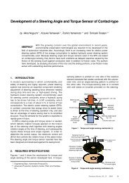
Figure 2<br />
Coupler<br />
Er-doped fiber<br />
Isolator<br />
980 nm<br />
1480 nm<br />
Signal<br />
Filter<br />
Configuration <strong>of</strong> optical fiber amplifier<br />
2. OPTICAL FIBER AMPLIFIER (OFA)<br />
Amplified<br />
Signal output<br />
Amplified<br />
signal<br />
Absorption and emission<br />
<strong>of</strong> Er-doped fiber<br />
It is no exaggeration to say that the invention <strong>of</strong> the optical<br />
fiber amplifier is the innovation making it possible to realize<br />
the WDM system. In particular, the <strong>EDFA</strong> 1) is very<br />
attractive <strong>for</strong> practical application because light amplification<br />
occurs in the wavelength range <strong>of</strong> the 1500-nm band,<br />
which is the low loss wavelength region <strong>of</strong> conventional<br />
silica fibers.<br />
Figure 2 illustrates the configuration <strong>of</strong> <strong>EDFA</strong>. It consists<br />
<strong>of</strong> EDF, a pumping laser module, a WDM coupler to couple<br />
the pumping light into EDF, an optical isolator to prevent<br />
the lasing in the EDF, and an optical fiber.<br />
<strong>High</strong> power lasers emitting at wavelengths <strong>of</strong> 980 nm<br />
and 1480 nm are used as pumping sources <strong>for</strong> effective<br />
pumping <strong>of</strong> EDF. Efficient power conversion can be realized<br />
with a 1480-nm pump 2) , while low noise amplification<br />
can be realized with a 980-nm pump. In practical application,<br />
1480-nm pumping is used as a booster amplifier and<br />
980-nm pumping is used as a pre-amplifier.<br />
3. SEMICONDUCTOR MATERIAL AND EPI-<br />
TAXIAL GROWTH<br />
1480-nm lasers can be fabricated using the conventional<br />
GaInAsP quaternary compound on an InP substrate,<br />
which has been used <strong>for</strong> telecommunication lasers emitting<br />
at 1300 nm and 1550 nm. We can use the established<br />
technology. On the other hand, 980-nm lasers cannot be<br />
fabricated by use <strong>of</strong> lattice matched materials. The wavelength<br />
<strong>of</strong> around 980 nm emitted from semiconductor<br />
lasers has been a <strong>for</strong>bidden wavelength region which cannot<br />
be covered by traditional short wavelength GaAsbased<br />
lasers (wavelength <strong>of</strong> shorter than 900 nm) and<br />
InP-based long wavelength lasers (wavelength longer<br />
than 1200 nm). The concept <strong>of</strong> strained-layer quantum<br />
wells 3), 4) , however, made it possible to realize 980-nm<br />
lasers as well as rapid progress <strong>of</strong> epitaxial growth technique<br />
to grow high quality very thin strained-layer material.<br />
980-nm lasers can be fabricated by use <strong>of</strong> an intentionally<br />
lattice-mismatched In x GaAs layer on a GaAs substrate.<br />
The In x GaAs strained-layer has a large lattice constant<br />
with respect to GaAs. If the layer thickness is controlled<br />
within the critical thickness calculated by Mathew's law,<br />
the layer can be grown with high crystalline quality on a<br />
GaAs substrate even if the InGaAs layer has a large<br />
amount <strong>of</strong> strain. This condition is approximately given by<br />
εL z < 20 nm% 5) , where ε is the amount <strong>of</strong> strain and L z is<br />
the layer thickness.<br />
Strained-layer GaInAsP on an InP substrate is also used<br />
<strong>for</strong> 1480-nm lasers since the concept <strong>of</strong> strained-layer<br />
quantum can improve the lasing characteristics drastically.<br />
Let's explain the quantum wells and strained-layer<br />
quantum wells used in high per<strong>for</strong>mance 980-nm and<br />
1480-nm lasers. Quantum wells are made up <strong>of</strong> two different<br />
materials with a layer thickness less than the de<br />
Broglie wavelength, say 20 nm. <strong>High</strong> material gain can be<br />
obtained with less carriers because carriers are effectively<br />
confined to the quantized state <strong>for</strong>med by the quantum<br />
well. In particular, the use <strong>of</strong> compressive strain into the<br />
quantum wells can change the modification <strong>of</strong> valence<br />
band structure in such a way that the effective mass <strong>of</strong><br />
heavy-hall becomes light. As a result, the Bernard-<br />
Duraffourg condition (Fermi-level separation larger than<br />
energy band-gap) can be satisfied with less carrier density.<br />
Thus, lower threshold current density and higher quantum<br />
efficiency can be obtained in strained-layer quantum<br />
well lasers.<br />
A strained-layer quantum well laser wafer can be grown<br />
by metalorganic chemical vapor deposition (MOCVD) <strong>for</strong><br />
both 980 nm and 1480 nm.<br />
4. APPROACH FOR HIGH POWER OPERA-<br />
TION<br />
In a practical application, a laser diode module, so-called<br />
pig tailed module, is used. The laser diode has to be<br />
designed in such a way that high power operation is<br />
obtained with a narrow and circular beam <strong>for</strong> high coupling<br />
into a single mode fiber (SMF). It should be noted<br />
that highly reliable operation under high output power has<br />
to be realized. For these purposes, buried heterostructure<br />
(BH) structure is used <strong>for</strong> 1480-nm lasers and a ridge<br />
waveguide (RWG) structure is used <strong>for</strong> 980-nm lasers.<br />
The limiting factors <strong>for</strong> high power operation under a<br />
continuous wave (CW) condition in these narrow stripe<br />
lasers are categorized into two phenomena; one is rollover<br />
phenomenon due to the increase <strong>of</strong> temperature in<br />
the active layer or increase <strong>of</strong> invalid current, and the<br />
other is catastrophic phenomenon mainly due to the optical<br />
mirror damage. The <strong>for</strong>mer is observed in 1480-nm<br />
lasers, and the latter is the sudden death phenomenon<br />
called catastrophic optical mirror damage (COD) and is<br />
observed mainly in 980-nm lasers. A detailed explanation<br />
<strong>of</strong> the COD is reported in reference 6.<br />
Let's explain the approach <strong>of</strong> how to attain high power<br />
operation in solitary lasers. The output power from the<br />
front facet, P f is given by the following equation if COD<br />
does not occur.<br />
P f = η i<br />
1 α m<br />
1+ 1-R f<br />
1-R r<br />
R r<br />
I ac<br />
x (I-I th ) Θ<br />
i+ (<br />
m I ac +I L<br />
)<br />
(T)<br />
α α<br />
R f<br />
24 Furukawa Review, No. 19. 2000
Where, η i : internal quantum efficiency, α i : internal loss,<br />
α m : mirror loss, I: injection current, I th : threshold<br />
current, I ac : effective current which contributes to<br />
the lasing, I L : leakage current, and Θ(T): term representing<br />
the optical power output saturation due<br />
to heat generation.<br />
From this equation, the following measures are thought<br />
to be effective <strong>for</strong> high power operation.<br />
(a) realization <strong>of</strong> high internal efficiency<br />
(b) introduction <strong>of</strong> asymmetric coating <strong>for</strong> low mirror loss<br />
(c) realization <strong>of</strong> low internal loss<br />
(d) suppression <strong>of</strong> leakage current<br />
(e) high thermal dissipation<br />
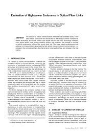
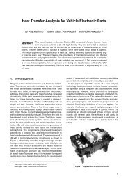
Figure 3<br />
TEM image <strong>of</strong> the active region <strong>of</strong> a 1480-nm laser<br />
Structural optimizations have to be made because contradictory<br />
items are included in the above. The introduction<br />
<strong>of</strong> a long cavity, <strong>for</strong> example, is effective <strong>for</strong> low thermal<br />
resistance, however, increase <strong>of</strong> the threshold current<br />
and decrease <strong>of</strong> external quantum efficiency are observed<br />
in long cavity lasers.<br />
Detailed explanations <strong>for</strong> realizing the above items are<br />
given as follows.<br />
(a) In order to achieve high internal quantum efficiency,<br />
structures <strong>of</strong> both quantum wells and optical confinement<br />
layers such as composition and thickness have to be optimized<br />
carefully. Introduction <strong>of</strong> strained layer quantum<br />
wells into the active layer is indispensable <strong>for</strong> this purpose.<br />
The use <strong>of</strong> GRIN-SCH (Graded-Index Separate-<br />
Confinement-Structure) is very effective 7) <strong>for</strong> high internal<br />
quantum efficiency, which will be described in detail later.<br />
(b) Parallel mirror <strong>for</strong>med by cleavage <strong>of</strong> semiconductor<br />
material is used <strong>for</strong> Fabry-Perot resonator, thus, an equal<br />
amount <strong>of</strong> light is emitted from both sides <strong>of</strong> the mirror.<br />
The output power from the rear facet is not so important<br />
because it is used only <strong>for</strong> a back-monitor in a practical<br />
application. There<strong>for</strong>e, asymmetric facet coatings composed<br />
<strong>of</strong> dielectric mirror are used to increase the output<br />
power from the front facet. Low reflective coating (several<br />
percent) is used <strong>for</strong> the front facet and high reflective coating<br />
(95%) is used <strong>for</strong> the rear facet.<br />
(c) Introduction <strong>of</strong> quantum well structure, especially a<br />
strained-layer quantum well is effective <strong>for</strong> low internal<br />
loss. A strained-layer quantum well laser can provide low<br />
threshold current and high differential quantum efficiency<br />
operation due to low internal loss even if a long cavity is<br />
used.<br />
(d) The reduction <strong>of</strong> leakage current leads to the suppression<br />
<strong>of</strong> temperature rise <strong>of</strong> the active layer, thus leading<br />
to the high power operation.<br />
(e) It is possible to reduce the temperature rise in the<br />
active layer by the use <strong>of</strong> a long cavity (low electric and<br />
thermal resistance) and junction down bonding on heat<br />
sink materials with high thermal conductivity such as diamond<br />
and AlN.<br />
Next, the output beam design <strong>for</strong> achieving high coupling<br />
into an SMF is explained. <strong>High</strong> coupling efficiency<br />
into an SMF is indispensable <strong>for</strong> fabricating a high power<br />
laser diode module. Narrow and circular output beams are<br />
favorable <strong>for</strong> efficient fiber coupling. Output beam characteristics<br />
can be controlled by the layer composition and<br />
thickness <strong>of</strong> the GaInAsP layer 7) which <strong>for</strong>m the SCH<br />
layer. In particular, the use <strong>of</strong> a GRIN-SCH layer can<br />
expand design freedom by not only taking into account the<br />
carrier confinement into the active layer but also optical<br />
confinement as well. It is theoretically and experimentally<br />
verified that the use <strong>of</strong> a GRIN-SCH layer compromising a<br />
thinner and wider bandgap is effective <strong>for</strong> both output<br />
beam characteristics and low threshold current, high<br />
quantum efficiency operations.<br />
It is noted that the packaging design, including coupling<br />
lens system, is also very important <strong>for</strong> high coupling efficiency<br />
into an SMF.<br />
5. CHARACTERISTICS OF 1480 NM<br />
LASERS<br />
Transmission electron microscopy <strong>of</strong> a cross sectional<br />
view <strong>of</strong> the active layer <strong>for</strong> a 1480-nm laser is shown in<br />
Figure 3. The active layer is made up <strong>of</strong> 1% compressively<br />
strained quantum wells (4 nm thick) separated by<br />
GaInAsP (10 nm thick) with a bandgap wavelength <strong>of</strong> 1.2<br />
µm. The number <strong>of</strong> wells is five. The GRIN-SCH layer,<br />
composed <strong>of</strong> two different GaInAsP, sandwiches the<br />
strained-layer active layer. The use <strong>of</strong> GRIN-SCH structure<br />
is shown to be effective <strong>for</strong> high per<strong>for</strong>mance in the<br />
long wavelength region 9) . Very sharp hetero-interfaces are<br />
obtained through MOCVD growth optimization.<br />
BH structure with an active layer width <strong>of</strong> 2 µm is used<br />
<strong>for</strong> both electrical and optical confinements. All epitaxial<br />
growth, including selective growth <strong>for</strong> BH structure using<br />
MOCVD process, ensures a high yield process using a 2-<br />
inch wafer.<br />
Figure 4 shows the injection current versus light output<br />
power characteristics <strong>for</strong> an optimized 1480-nm laser. The<br />
cavity length is 1200 µm <strong>for</strong> high heat dissipation, which is<br />
longer than those <strong>of</strong> conventional lasers having typical<br />
cavity lengths <strong>of</strong> 300-400 µm used <strong>for</strong> telecommunication<br />
applications. In order to increase the heat dissipation, the<br />
25
400<br />
600<br />
35˚C, 160-180 mW<br />
Output power (mW)<br />
300<br />
200<br />
100<br />
λ=1480 nm<br />
L=1200 µm<br />
AR/HR<br />
P max =360 mW<br />
Driving current (mA)<br />
400<br />
60˚C, 80-110 mW<br />
200<br />
Automatic power control<br />
0<br />
0 500 1000<br />
1500<br />
0<br />
0 5,000 10,000 15,000 20,000<br />
Injection current (mA)<br />
Aging time (hrs)<br />
Figure 4<br />
I-L characteristics <strong>of</strong> 1480-nm laser<br />
Figure 6<br />
Reliability test results <strong>of</strong> 1480-nm laser<br />
100 mW<br />
Figure 5<br />
Angle (deg.)<br />
θ Ver.<br />
:25 deg.<br />
100 mW<br />
Angle (deg.)<br />
θ Parall<br />
:20 deg.<br />
Output beam pattern <strong>of</strong> 1480-nm laser<br />
laser is bonded with a junction down configuration, that is,<br />
the laser is bonded on a heat sink in such a way that the<br />
active layer, which is the main heat generator, lies close to<br />
the heat sink. The facet is coated with an AR/HR film. The<br />
reflectivities are 5% and 95% <strong>for</strong> front and rear facets,<br />
respectively. Low threshold current <strong>of</strong> 25 mA was<br />
obtained in spite <strong>of</strong> a long cavity <strong>of</strong> 1200 µm. Output<br />
power as high as 360 mW from the front facet was<br />
achieved, which, to the best <strong>of</strong> our knowledge, is the maximum<br />
output power ever reported <strong>for</strong> transverse-mode<br />
stabilized long wavelength lasers 7) . <strong>High</strong> output power <strong>of</strong><br />
over 300 mW was obtained even at a high temperature <strong>of</strong><br />
50°C. Extremely high output power was obtained <strong>for</strong> this<br />
particular device with a long cavity, however, driving current<br />
or power consumption is relatively high <strong>for</strong> 100-200<br />
mW output power, which is commonly used <strong>for</strong> practical<br />
application. There<strong>for</strong>e, a cavity length around 800-1000<br />
µm is used <strong>for</strong> low power consumption operation.<br />
Maximum output power is decreased due to the poor heat<br />
dissipation, however, driving current <strong>for</strong> 100-200 mW can<br />
be decreased because <strong>of</strong> higher differential quantum efficiency.<br />
Figure 5 shows the far field pattern (FFP) parallel and<br />
perpendicular to the junction plane at an output power <strong>of</strong><br />
100 mW. Full-width at half-maximums <strong>of</strong> FFP parallel and<br />
perpendicular to the junction plane are 20° and 25°,<br />
respectively. The narrow and circular output beam<br />
obtained here is favorable <strong>for</strong> high coupling into SMF.<br />
<strong>High</strong>ly reliable operation must be achieved like conventional<br />
FP and DFB lasers since optical fiber amplifiers are<br />
used <strong>for</strong> long-haul trunk lines and submarine optical communication<br />
systems. Output power <strong>of</strong> pumping lasers is<br />
extremely high as compared to conventional signal lasers.<br />
Reliability test under high temperature and high output<br />
power has to be investigated. Figure 6 shows the aging<br />
test result at high power condition. The aging test has<br />
been per<strong>for</strong>med at 35°C and 60°C in the automatic power<br />
control mode. The output power is set to be 80% <strong>of</strong> the<br />
maximum output power at a given temperature, determined<br />
by the thermal roll-over, which is 180 mW at 35°C<br />
and 120 mW at 60°C. Stable operation has been confirmed<br />
after 20000 hours without appreciable increase <strong>of</strong><br />
driving current. The activation energy <strong>of</strong> 0.62 eV is derived<br />
from various aging test conditions. Extremely high reliability<br />
<strong>of</strong> 100 million hours as a mean time to failure (MTTF) is<br />
estimated at an output power <strong>of</strong> 150 mW, which corresponds<br />
to the module output power <strong>of</strong> 120 mW (reasonable<br />
coupling efficiency into an SMF <strong>of</strong> 80% is assumed) .<br />
6. CHARACTERISTICS OF 980-NM<br />
LASERS<br />
The noise figure <strong>of</strong> fiber amplifiers pumped at 980 nm is<br />
lower than that <strong>of</strong> fiber amplifiers pumped at 1480 nm,<br />
which is very attractive <strong>for</strong> practical application.<br />
The material candidate <strong>for</strong> 980-nm lasers is compressively<br />
strained InGaAs quantum wells <strong>for</strong> the active layer,<br />
while there are two candidates <strong>for</strong> cladding layer materials.<br />
Those are conventional AlGaAs 10)~14) layer and novel<br />
InGaP 15), 16) layers. The use <strong>of</strong> InGaP cladding layer material<br />
might have an advantage over AlGaAs in terms <strong>of</strong> less<br />
oxidized property and slow surface recombination velocity,<br />
which are thought to be effective methods to suppress<br />
COD.<br />
As mentioned previously, transverse-mode stabilized<br />
laser structure is used <strong>for</strong> efficient coupling to SMF. Ridge<br />
waveguide structure is widely used as shown in Figure 7.<br />
This laser structure is grown by MOCVD. <strong>Recent</strong>ly, other<br />
laser structures like buried ridge waveguide structure and<br />
self-aligned-structure (SAS) have been investigated.<br />
Light output power versus injection current characteristics<br />
is shown in Figure 8 <strong>for</strong> a 980-nm RWG laser with 4<br />
µm-wide ridge and 800 µm-long cavity. Light output power<br />
26 Furukawa Review, No. 19. 2000
Metal<br />
p-GaAs<br />
p-AlGaAs clad<br />
n-AlGaAs clad<br />
AlGaAs<br />
HR Film<br />
Output power (mW)<br />
300<br />
200<br />
100<br />
λ=980 nm<br />
25˚C, CW<br />
1.0<br />
0.5<br />
Efficiency (W/A)<br />
AR Film<br />
Figure 7<br />
n-GaAs sub.<br />
GaAsP InGaAs<br />
Structure <strong>of</strong> ridge-waveguide type 980-nm laser<br />
0<br />
0 100 200 300 400 500<br />
Injection current (mA)<br />
Figure 10 I-L characteristics <strong>of</strong> 980-nm laser module<br />
Output power (mW)<br />
500<br />
400<br />
300<br />
200<br />
100<br />
λ=980 nm<br />
L=800 µm<br />
AR/HR<br />
SE: 1W/A<br />
θ parall.<br />
: 9 deg.<br />
θ ver.<br />
: 23 deg.<br />
Output power (mW)<br />
400<br />
300<br />
200<br />
100<br />
λ=1480 nm<br />
25˚C, CW<br />
Pf>300 mW<br />
0<br />
0 100 200 300 400 500<br />
Injection current (mA)<br />
Angle (deg.)<br />
0<br />
0 500 1000 1500<br />
Injection current (mA)<br />
Figure 8<br />
I-L characteristics <strong>of</strong> 980-nm laser<br />
Figure 11 I-L characteristics <strong>of</strong> 1480-nm laser module<br />
Driving current (mA)<br />
500<br />
400<br />
300<br />
200<br />
100<br />
λ=980 nm<br />
60˚C, 250 mW<br />
Automatic power control<br />
atmosphere and in-situ facet passivation, facet passivation<br />
using high thermal conductivity material, and <strong>for</strong>mation<br />
<strong>of</strong> so-called 'window structure' near the facet, which is<br />
transparent to the emission wavelength.<br />
Long term aging result is shown in Figure 9 under conditions<br />
<strong>of</strong> 60°C, 250 mW. No appreciable change in driving<br />
current has been observed after 5000 hours.<br />
0<br />
0<br />
Figure 9<br />
1000 2000 3000 4000 5000<br />
Aging time (hrs)<br />
Reliability test results <strong>of</strong> 980-nm laser<br />
more than 300 mW was successfully achieved with a<br />
slope efficiency as high as 1 W/A. FFPs parallel and perpendicular<br />
to the junction plane are also shown in Figure 8<br />
at an output power <strong>of</strong> 250 mW, showing an elliptical output<br />
beam as compared to BH lasers. It is possible to<br />
obtain high coupling efficiency by optimizing a coupling<br />
scheme. With a wedge-shaped fiber, which is specially<br />
designed <strong>for</strong> beam shape, coupling efficiency as high as<br />
80% was achieved.<br />
Similar to 1480-nm lasers, highly reliable operation is<br />
required. One <strong>of</strong> the key items <strong>for</strong> high reliability operation<br />
is to overcome COD. Key technology is facet passivation<br />
technology. Several approaches have been reported,<br />
those are, cleavage laser bars in the ultra-high-vacuum<br />
7. LASER MODULE<br />
Figures 10 and 11 show the light output power versus<br />
injection current characteristics <strong>of</strong> 980-nm and 1480-nm<br />
laser modules, respectively. Very high coupled powers <strong>of</strong><br />
200 mW <strong>for</strong> a 980-nm laser module 17) and <strong>of</strong> over 300 mW<br />
<strong>for</strong> a 1480-nm laser module 18) are obtained.<br />
In particular, coupled power <strong>of</strong> over 300 mW is the highest<br />
power reported <strong>for</strong> long wavelength laser modules with<br />
SMF. Extremely high coupled power modules <strong>of</strong> 250 mW<br />
are commercially available.<br />
The failure mode related to the packaging has been<br />
reported in 980-nm laser modules. It is considered that<br />
hydrocarbon, contained in epoxy used <strong>for</strong> package and<br />
adhering to the laser facet is the trigger <strong>for</strong> COD. This failure<br />
mode is called PIF (package induced failure). One<br />
solution to avoid PIF is to introduce a small amount <strong>of</strong><br />
oxygen into the package to burn out the hydrocarbon<br />
adhered to the laser facet.<br />
27
CW Output power (mW)<br />
400<br />
300<br />
200<br />
100<br />
'87<br />
Innovation<br />
Phillips<br />
NEC<br />
NEC<br />
Philips<br />
AT&T<br />
Oki<br />
Oki<br />
Furukawa<br />
Bulk QW SL-QW<br />
Furukawa<br />
SEI<br />
BT&D<br />
SEI<br />
Oki<br />
Fujitsu<br />
'89 '91 '93 '95 '97 '99<br />
Year reported<br />
Mitsubishi<br />
Optimization<br />
Furukawa<br />
NEC<br />
λ=1480 nm<br />
achieved. New technological innovations such as a novel<br />
active layer structure and some consideration <strong>for</strong> active<br />
layer material can lead to further output power improvement<br />
in the future.<br />
ACKNOWLEDGEMENT<br />
The authors would like to thank Drs. K. Ohkubo, Y.<br />
Suzuki, T. Kamiya <strong>for</strong> their encouragement and also the<br />
entire pump laser team including FITEL products division.<br />
Figure 12 Improvements in light output <strong>of</strong> 1480-nm laser<br />
Several types <strong>of</strong> laser modules have been fabricated <strong>for</strong><br />
WDM application. Wavelength stabilized laser module is<br />
one example 19) . Lasing wavelength can be stabilized by<br />
the use <strong>of</strong> fiber Bragg grating. In general, lasing wavelength<br />
<strong>of</strong> FP lasers shifts to longer wavelengths with a<br />
temperature coefficient <strong>of</strong> 0.5 nm/degree in the 1480-nm<br />
wavelength. By using fiber Bragg grating with a narrow<br />
pass band, a stable lasing wavelength <strong>for</strong> both current<br />
and temperature can be achieved.<br />
8. FUTURE PROSPECT<br />
The history <strong>for</strong> power improvement in narrow stripe (transverse-mode<br />
stabilized) 1480-nm lasers is shown in Figure<br />
12. Drastic power improvement has been achieved by<br />
technological innovations, such as, introduction <strong>of</strong> quantum<br />
well active layer and strained-layer quantum well<br />
active layer. By using a strained-layer quantum well active<br />
layer, maximum output power <strong>of</strong> about 400 mW was<br />
REFERENCES<br />
1) S. B. Poole et al: Electron. Lett., 21 (1985) 737.<br />
2) K. Nishimura : Optical soliton transmission Technical Report ,<br />
1995, p.57. (in Japanese)<br />
3) E. Yablonovitch at al: J. Lightwave Technol., LT-4 (1986) 504.<br />
4) A. R. Adams: Electron. Lett., 22 (1986) 249.<br />
5) T. J. Andersson et al.: Appl. Phys. Lett., 51 (1987) 752.<br />
6) I. Mito et al.: Applied Physics Japan, 64 (1995) 2. (in Japanese)<br />
7) A. Kasukawa et al.: IEEE Photon. Technol. Lett., 1 (1994) 4.<br />
8) A. Kasukawa et al.: OPTOELECTRONICS-Device and<br />
Technologies, 9 (1994) 219.<br />
9) H. Hirayama et al.: IEEE J. Quantum Electron., 28 (1992) 68.<br />
10) D. Fekete et al.: Appl. Phys. Lett., 49 (1986) 1659.<br />
11) M. Okayasu et al.: IEEE Photon. Technol. Lett., 2 (1990) 689.<br />
12) S. Ishikawa et al.: IEEE J. Quantum Electron., 29 (1993) 1936.<br />
13) H. Meier: Technical Digest <strong>of</strong> 20 th European Conference on<br />
Optical Communications, Firenze, Sep., 1994, p.974.<br />
14) J. S. Major et al.: Electron. Lett., 27 (1991) 540.<br />
15) S. Sagawa et al.: Technical Digest <strong>of</strong> 14 th International<br />
<strong>Semiconductor</strong> Laser Conference, Maui, Sep., 1994, p.255.<br />
16) M. Ohkubo et al.: IEEE J. Quantum Electron., 30 (1994) 1936.<br />
17) Y. Irie et al.: OFC/IOOC'99, Paper WM15 (1999).<br />
18) T. Kimura et al.: OAA'99, Paper ThD12 (1999).<br />
19) S. Koyanagi et al.: OAA'98, p.35 (1998).<br />
Manuscript received on December 17, 1999.<br />
28 Furukawa Review, No. 19. 2000