Evaluation of High-power Endurance in Optical Fiber Links
Evaluation of High-power Endurance in Optical Fiber Links
Evaluation of High-power Endurance in Optical Fiber Links

You also want an ePaper? Increase the reach of your titles
YUMPU automatically turns print PDFs into web optimized ePapers that Google loves.
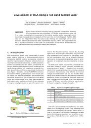
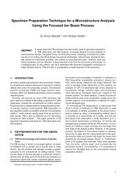
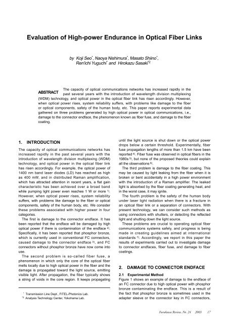
<strong>Evaluation</strong> <strong>of</strong> <strong>High</strong>-<strong>power</strong> <strong>Endurance</strong> <strong>in</strong> <strong>Optical</strong> <strong>Fiber</strong> L<strong>in</strong>ksdamage the endface whether alcohol is present or not,and it may also be dangerous to the human body.Therefore, connectors exposed to high-<strong>power</strong> lightneed careful handl<strong>in</strong>g, and clean<strong>in</strong>g and check<strong>in</strong>g <strong>of</strong> theendface should only be carried out with the light sourceturned <strong>of</strong>f.3. FIBER FUSE3.1 Experimental Method<strong>Fiber</strong> fuse is a phenomenon <strong>in</strong> which voids are formedtypically hav<strong>in</strong>g the shape <strong>of</strong> bullets <strong>in</strong> the core area, andpropagate as shown <strong>in</strong> Figure 2. Propagation cont<strong>in</strong>uesas long as optical <strong>power</strong> is provided until the light sourceis shut down or the <strong>power</strong> drops below a certa<strong>in</strong> threshold,and may eventually reach the light source and damage it.In this work, we measured the threshold <strong>power</strong> at whichfiber fuse stops propagat<strong>in</strong>g.Figure 3 shows the test setup. We used two lightsources with peak wavelengths <strong>of</strong> 1064 and 1467 nm.The po<strong>in</strong>t to be noted here is that fiber fuse does notnecessarily occur, even under high light <strong>power</strong>. It hasbeen reported that the silicon fiber itself can withstandover 10 GW/cm 2 and generally SMF is sufficiently durableto withstand light <strong>in</strong>tensities <strong>in</strong> the order <strong>of</strong> several Watts.If, however, there is some trigger to <strong>in</strong>itiate fiber corefusion at some po<strong>in</strong>t, from which it will propagate towardthe light source. In actual light transmission paths, lightabsorption by contam<strong>in</strong>ants adher<strong>in</strong>g to a connectorendface, or the concentration <strong>of</strong> light energy by multirefectionat fiber breaks can constitute such a trigger. Theprobability <strong>of</strong> fiber fuse <strong>in</strong>itiation thus tends to <strong>in</strong>creaseas optical <strong>in</strong>tensity rises, but the probability and threshold<strong>power</strong> for the <strong>in</strong>itiation <strong>of</strong> fiber fuse differ dramaticallyaccord<strong>in</strong>g to what the trigger is.Dur<strong>in</strong>g this <strong>in</strong>vestigation, <strong>in</strong> order to <strong>in</strong>crease theprobability <strong>of</strong> fiber fuse easily, fibers carry<strong>in</strong>g 5 W <strong>of</strong> laserlight <strong>power</strong> were heated locally by arc discharge to over1000°C. Once fiber fuse occurred, we decreased the light<strong>in</strong>tensity level gradually by adjust<strong>in</strong>g the bias level <strong>of</strong> thelaser source until fiber fuse stopped, and measured that<strong>power</strong> level which is the threshold value. This threshold<strong>power</strong> for fuse propagation is determ<strong>in</strong>ed solely by fibertype and laser light wavelength, and is <strong>in</strong>dependent <strong>of</strong> themethod <strong>of</strong> fuse <strong>in</strong>itiation. And s<strong>in</strong>ce this threshold <strong>power</strong> isthe level below which fiber fuse cannot propagate, we alsobelieve it to be the po<strong>in</strong>t below which it cannot be <strong>in</strong>itiated.3.2 Threshold Power <strong>of</strong> <strong>Fiber</strong> Fuse PropagationFigure 4 shows the <strong>power</strong> threshold for fuse propagationmeasured at two wavelengths for SMF and ITU-T G.653dispersion shifted fiber (DSF). The fact that the <strong>power</strong>threshold is lower for DSF than for SMF is thought to bedue to the higher <strong>power</strong> density because <strong>of</strong> the smallermode field diameter (MFD). Figure 5 shows the threshold<strong>power</strong> for several fibers with different MFD, measured ata peak wavelength <strong>of</strong> 1467 nm. The fibers used weredispersion compensat<strong>in</strong>g fiber (DCF) for SMF, DSF, andlocally core expanded SMF (diameters <strong>of</strong> 20 μm and 30μm). For SMF, DSF, and DCF, the actual measured valuesare plotted and for the core-expanded fibers is shown asa range, the value at which the fuse passed the expandedpart plotted as maximum and the value at which it stoppedas the m<strong>in</strong>imum.Aga<strong>in</strong>st our expectations, the result showed that the<strong>power</strong> threshold is <strong>in</strong> proportion not to effective area (A eff ),but to MFD. If the <strong>power</strong> were <strong>in</strong> proportion to A eff , thePower threshold (W)2.01.51.00.5SMFDSF0800 1000 1200 1400 1600Center wavelength (nm)Figure 4 Wavelength dependence <strong>of</strong> <strong>power</strong> threshold for fiberfuse propagation.5.0λ=1467nmLight source1064 nm, 5 W1467 nm, 5 WFigure 2 <strong>Optical</strong> fiber after fuse propagation.<strong>Optical</strong> fiber(10~20 m)Direction <strong>of</strong> light <strong>power</strong>propagationDirection <strong>of</strong> fiber fuse propagationHeat<strong>in</strong>g by arc dischargeFigure 3 Setup for test<strong>in</strong>g fiber fuse.Power meterPower threshold (W)4.03.02.01.000 5 10 15 20 25 30 35MFD ( µ m)Figure 5 MFD dependence <strong>of</strong> <strong>power</strong> threshold for fiberfuse propagation.Furukawa Review, No. 24 2003 19
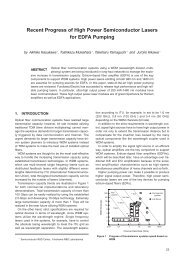
<strong>Evaluation</strong> <strong>of</strong> <strong>High</strong>-<strong>power</strong> <strong>Endurance</strong> <strong>in</strong> <strong>Optical</strong> <strong>Fiber</strong> L<strong>in</strong>ksplotted data would not be on a straight l<strong>in</strong>e, but on thelocus <strong>of</strong> a quadratic equation. However, we were able toconfirm that expand<strong>in</strong>g the MFD is an effective way toraise the <strong>power</strong> threshold for fiber fuse propagation.3.3 Consideration <strong>of</strong> <strong>Fiber</strong> Fuse andCountermeasures AdoptedAll that is necessary to assure that fiber fuse is not<strong>in</strong>itiated is to keep the optical <strong>power</strong> <strong>of</strong> the light sourcebelow the propagation threshold. For example, we havefound experimentally that at 1467 nm, the pump<strong>in</strong>g lightwavelength, the <strong>power</strong> threshold <strong>of</strong> SMF is approximately1.5 W, so that it is certa<strong>in</strong>ly safe with respect to fiberfuse when operated below this level. However, s<strong>in</strong>ce the<strong>power</strong> levels <strong>in</strong> fiber optic communication networks mayrise to more than 1.5 W, technology for stopp<strong>in</strong>g fusepropagation is also needed.Detect<strong>in</strong>g optical output <strong>power</strong> and turn<strong>in</strong>g <strong>of</strong>f the laserlight source is the most effective method to stop fiberfuse propagation. When fiber fuse is <strong>in</strong>itiated, output<strong>power</strong> decreases precipitously, as shown <strong>in</strong> Figure 6,so, if the drop is detected and the laser source turned<strong>of</strong>f immediately, the propagation will stop, because thepropagation speed is several meters per second at most.Especially, an automatic <strong>power</strong> reduction (APR) system,which is described <strong>in</strong> ITU-T as a method for shutt<strong>in</strong>g downthe light source <strong>in</strong> case <strong>of</strong> fiber breakage, is effective notonly <strong>in</strong> terms <strong>of</strong> safety to the human body, but also <strong>of</strong> fiberfuse.There is also another technique that is effective <strong>in</strong>provid<strong>in</strong>g an area <strong>of</strong> expanded MFD <strong>in</strong> the optical path.For example, we made SC connectors us<strong>in</strong>g fibers withpartially expanded MFD, as shown <strong>in</strong> Figure 7. The length<strong>of</strong> the expanded part is about 4 mm, the expanded MFDis 30 μm, and the MFD at the endface is 10 μm, so theseconnectors are compatible with standard SC connectors.It was confirmed experimentally that they can stop fusepropagation at 4-W transmission at a peak wavelength <strong>of</strong>1467 nm.Light <strong>power</strong> (W)5432100 1 2 3 4 5Time (m<strong>in</strong>)Figure 6 Power meter read<strong>in</strong>gs on changes <strong>in</strong> output <strong>power</strong>for tests accord<strong>in</strong>g to Figure 3.MFD ( µ m)20151050-5-10-15--200 1 2 3 4 5 6Light source1480 nm,3 W maximum<strong>Fiber</strong> fuse <strong>in</strong>itiated hereDistance from connector endface (mm)Figure 7 Pr<strong>of</strong>ile <strong>of</strong> MFD.Coat<strong>in</strong>g on SMF:7 8 9 10 11 12<strong>Fiber</strong> bend<strong>in</strong>g diameter:φ 30, 20, 10, 5 mmUV (transparent, white, green),nylon (white)Figure 8 Setup for test<strong>in</strong>g damage to fiber coat<strong>in</strong>g.64. DAMAGE TO FIBER COATING4.1 Experimental MethodTight bend<strong>in</strong>g <strong>of</strong> optical fibers is not conducive to longtime reliability, but <strong>in</strong> actual systems fibers may be tightlybent. When tightly bent the light is radiated to the fibercoat<strong>in</strong>g, which is heated particularly under high <strong>power</strong>conditions. We have <strong>in</strong>vestigated damage to the fibercoat<strong>in</strong>g <strong>in</strong>duced by tight bend<strong>in</strong>g under high <strong>power</strong>conditions <strong>in</strong> the short term.Figure 8 shows the test setup for the <strong>in</strong>vestigation.We used a 1480 nm high-<strong>power</strong> light source hav<strong>in</strong>g amaximum output <strong>power</strong> <strong>of</strong> 3 W. The fibers tested wereG.652 fiber, with coat<strong>in</strong>g <strong>of</strong> 0.25 mm UV curable res<strong>in</strong>(transparent, white, and green) and 0.9 mm tight buffer(white nylon). The bend<strong>in</strong>g diameters <strong>of</strong> the fibers were30 mm, 20 mm, 10 mm, and less than 5 mm. The ambienttemperature was approximately 25°C.First, the temperature changes at a po<strong>in</strong>t on fibers bentto a 3-mm diameter were measured at 3 W <strong>in</strong>put <strong>power</strong>,as shown <strong>in</strong> Figure 9. This shows that heat equilibrium isreached with<strong>in</strong> 5 m<strong>in</strong>utes, so <strong>in</strong> our experiments the testedfibers were exposed to high <strong>in</strong>put <strong>power</strong> for 5 m<strong>in</strong>utes.4.2 <strong>Evaluation</strong> <strong>of</strong> Damage to <strong>Fiber</strong> Coat<strong>in</strong>gsThe experimental results after 5 m<strong>in</strong>utes exposure areshown <strong>in</strong> Table 3. We dist<strong>in</strong>guished the conditions <strong>of</strong>coat<strong>in</strong>g damage qualitatively <strong>in</strong>to four stages: “deformed”means that the coat<strong>in</strong>g res<strong>in</strong> is hardened by the heat;“discolored” means that, <strong>in</strong> addition, the color <strong>of</strong> coat<strong>in</strong>gbecomes dull; “melted” means that a part <strong>of</strong> the coat<strong>in</strong>gmelted; “ignited” means that the coat<strong>in</strong>g burst <strong>in</strong>to flameand burned.In the case <strong>of</strong> bend<strong>in</strong>g diameters <strong>of</strong> less than 5 mm, thenylon coat<strong>in</strong>gs were melted at 1 W and ignited at 3 W, andFurukawa Review, No. 24 2003 20
<strong>Evaluation</strong> <strong>of</strong> <strong>High</strong>-<strong>power</strong> <strong>Endurance</strong> <strong>in</strong> <strong>Optical</strong> <strong>Fiber</strong> L<strong>in</strong>ks5. CONCLUSIONThe capacity <strong>of</strong> optical communications networks has<strong>in</strong>creased rapidly <strong>in</strong> the past several years with the<strong>in</strong>troduction <strong>of</strong> wavelength division multiplex<strong>in</strong>g (WDM)technology, and optical <strong>power</strong> <strong>in</strong> the optical fiber l<strong>in</strong>k hasrisen accord<strong>in</strong>gly. However, when optical <strong>power</strong> rises,system reliability suffers, with problems like damage tothe fiber or optical components, safety <strong>of</strong> the human body,etc. This paper reports experimental data gathered onthree problems generated by high optical <strong>power</strong> <strong>in</strong> opticalcommunications, i.e., damage to the connector endface,the phenomenon known as fiber fuse, and damage to thefiber coat<strong>in</strong>g.This time, the qualitative tendency and a certa<strong>in</strong>quantitative prospect were obta<strong>in</strong>ed about three high<strong>power</strong> problems. More data must be accumulated <strong>in</strong>order to reach a conclusion as to reliability or guaranteedvalues. We plan to cont<strong>in</strong>ue these evaluations andwant to contribute to the development <strong>of</strong> an optical fibercommunications system with products <strong>of</strong> higher <strong>power</strong>durability and safety.REFERENCES1) Y. Emori, Y. Akasaka and S. Namiki, “Less than 4.7 dB noisefigure broadband <strong>in</strong>-l<strong>in</strong>e EDFA with a Raman amplifier-1300ps/nm DCF pumped by multi-channel WDM laser diodes,” <strong>in</strong>Tech. Dig. OAA ’98, Vail CO, July ’98, paper PD3.2) M. E. De Rosa, V. A. Bhagavatula, Q. Wu., K. Matusick,“<strong>High</strong> optical <strong>power</strong> test<strong>in</strong>g <strong>of</strong> physical contact connectors at1550nm,” OFC’01, Technical Digest, TuI7-1.3) J. Nakajima, H. Takara and S. Nishi, “Temperature <strong>in</strong>crease<strong>of</strong> optical connector end face due to spot heated by high<strong>power</strong> light,” IEICE’91, B-5744) Raman Kashyap, “Self-propelled self-focus<strong>in</strong>g damage <strong>in</strong>optical fibers,” Electronics Letters 7th, Jan.1988, Vol24,No.1.5) D.P. Hand and P. St. J. Russell, “Solitary thermalshockwaves and optical damage <strong>in</strong> optical fibers: the fiberfuse,” Opt. Lett. V13 p767 (1988).6) D.D. Davis, S.C. Mettler and D.J. DiGiovanni, “Acomparative evaluation <strong>of</strong> fiber fuse models,” SPIE 2966,592-606 (1997).7) “<strong>Optical</strong> safety procedures and requirements for opticaltransport systems,” <strong>in</strong> ITU-T, G.6648) S. Yanagi, S. Asakawa and R. Nagase, “Characteristics<strong>of</strong> fibre-optic connector at high-<strong>power</strong> optical <strong>in</strong>cidence,”Electronics Letters 15th, Aug.2002, Vol38, No.17.9) Stolen R H, “<strong>Optical</strong> fibre communications,” Miller S E &Chynoweth A G, eds., Academic Press, 1979.Furukawa Review, No. 24 2003 22