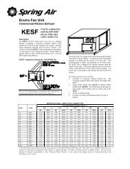
KES Enviro - Spring Air Systems Inc.
KES Enviro - Spring Air Systems Inc.
KES Enviro - Spring Air Systems Inc.

You also want an ePaper? Increase the reach of your titles
YUMPU automatically turns print PDFs into web optimized ePapers that Google loves.
<strong>KES</strong> <strong>Enviro</strong><br />
(With MXFLO)<br />
Maintenance Manual<br />
___________________________<br />
January 08<br />
<strong>Spring</strong> <strong>Air</strong> <strong>Systems</strong> <strong>Inc</strong>.<br />
Phone (905) 338-2999, Fax (905) 338-0179, info@springairsystems.com<br />
www.springairsystems.com
<strong>KES</strong> <strong>Enviro</strong> Maintenance Manual<br />
Table of Contents<br />
Introduction 1<br />
The System 1<br />
Control Circuit 3<br />
Control <strong>Systems</strong>: Dry Hoods 8<br />
Control System: Water wash 10<br />
MXFLOW Option 13<br />
Checking Fan Rotation with MXFLOW Option 15<br />
Changing the Exhaust Volume with MXFLOW Option 16<br />
Odor Spray System 17<br />
Where to Purchase Filters 19<br />
Replacement Filter Equivalents 19<br />
When to Change the <strong>KES</strong> Filters 20<br />
Trouble Shooting 22<br />
<strong>KES</strong> Maintenance Schedule 24<br />
Appendix A: MXFLOW only: Setting the DMP 26<br />
Appendix B: MXFLOW only: Factory Drive Terminal Schematic 28<br />
Appendix C: Hazardous Warning 30<br />
Appendix D: MXFLOW only: Good Wiring Practice 31<br />
Appendix E: MXFLOW only: Grounding 32<br />
Appendix F: MXFLOW only: Starting the Drive 33<br />
Appendix G: MXFLOW only: Accessing the drive program menu 34<br />
Appendix H: MXFLOW only: Programming the Drive Parameters 36<br />
Appendix I: MXFLOW only: Trouble Shooting the Drive Fault Display 37<br />
Appendix J: MXFLOW Factory wiring 42<br />
Appendix K: Programming the SMART clock 43<br />
Appendix L: Setting the Filter Out and Filter Clogged in PLC 46<br />
Appendix M: <strong>KES</strong> Logo Factory Wiring Diagram 52<br />
<strong>KES</strong> <strong>Enviro</strong> Start-Up Report 53<br />
Jan08
<strong>KES</strong> ENVIRO OPERATION AND MAINTENANCE MANUAL<br />
INTRODUCTION<br />
Thank you for purchasing a <strong>Spring</strong> <strong>Air</strong> <strong>Systems</strong> commercial kitchen ventilation product. Please read the<br />
complete “<strong>KES</strong> <strong>Enviro</strong> Operation and Maintenance Manual” prior to installation, commissioning or operating<br />
a <strong>KES</strong> unit.<br />
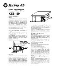
The SPRING AIR SYSTEMS INC. kitchen <strong>Enviro</strong> system (<strong>KES</strong>), Exhaust Cleaning Assembly for Kitchen<br />
Exhaust Duct, “<strong>Enviro</strong> Unit” is ULC and UL listed for use in a commercial kitchen exhaust system. <strong>KES</strong> units<br />
are available in sizes ranging from 1,000 CFM to 40,000 CFM for indoor or outdoor applications.<br />
The primary function of a <strong>KES</strong> <strong>Enviro</strong> unit is to filter the grease, lint and dust particles and remove the odor<br />
from the exhaust air.<br />
The Underwriters Laboratories <strong>Inc</strong>. (UL) and Underwriters’ Laboratories of Canada Limited (ULC) listings<br />
allow the kitchen exhaust air to be discharge to atmosphere at low levels.<br />
Prior to any installation the installer must seek approval from the authorities having jurisdiction.<br />
<strong>KES</strong>-ISH <strong>Enviro</strong> Filter Box<br />
Figure 1<br />
<strong>KES</strong>F <strong>Enviro</strong> Fan Box<br />
Figure 2<br />
THE SYSTEM<br />
The grease-laden air rises from the cooking equipment into a UL or ULC exhaust hood. The exhaust hood<br />
removes some of the airborne grease particulate. Typically most micron and submicron particles escape<br />
into the exhaust ductwork. The exhaust ducting is connected from the hood to the inlet of the <strong>KES</strong> <strong>Enviro</strong><br />
unit. This exhaust ductwork must be supplied and installed in accordance with the NFPA-96 code.<br />
Exhaust to<br />
atmophere at<br />
low level<br />
Discharge Ductwork<br />
<strong>KES</strong>F Fan Box<br />
Interconnecting Ductwork<br />
Remote<br />
RPW(D) Panel<br />
<strong>KES</strong>-ISH Filter Box<br />
Water Wash<br />
Panel<br />
NFPA-96 Ductwork<br />
Appliance Line-up<br />
Listed Exhaust Hood<br />
<strong>KES</strong> System Schematic<br />
Figure 3<br />
<strong>Enviro</strong> Maintenance Manual 2008 1
Once through the particulate filter sections the exhaust air enters the optional odor removal section. The<br />
odor section is only required when discharging cooking smells may be offensive. This section consists of<br />
two optional odor removal systems.<br />
1. Odor Cells filled with activated alumina impregnated with potassium permanganate. The odor is<br />
controlled through a combination of sorption and the chemical modification of the gaseous<br />
contaminates. The odor media is non-toxic and non-flammable.<br />
2. Odor spray solution. The odor is control by spraying<br />
an odor reducer into the exhaust air stream<br />
intermittently during the operation of the cooking<br />
systems. The odor spray unit is normally located<br />
mounted on the <strong>KES</strong>F fan section. The cabinet<br />
includes an air compressor, atomizing air nozzle and<br />
piping and odor spray container.<br />
Odor Spray components<br />
Figure 4<br />
<strong>KES</strong>-ISH and <strong>KES</strong>F <strong>Enviro</strong> components<br />
Figure 5<br />
The exhaust air is discharged from the <strong>KES</strong> unit through a single width, single inlet (SWSI) or double width,<br />
double inlet (DWDI) exhaust fan. The discharge ductwork transfers the exhaust air outdoors.<br />
<strong>Enviro</strong> Maintenance Manual 2008 Revision 1.0<br />
2
CONTROL CIRCUIT<br />
Filter Clogged:<br />
During normal operation of the <strong>KES</strong> unit three-filter stages collect grease, dust, and lint particulate. The type<br />
of cooking equipment and the hours of operation determines the useful life of the individual filters.<br />
Pressure Transmitter Locations<br />
Figure 6<br />
Box Filter probes as viewed<br />
from discharge<br />
Figure 7<br />
<strong>Enviro</strong> Maintenance Manual 2008 Revision 1.0<br />
3
Typical indoor <strong>KES</strong>, motor starter, LV10 J-Box with odor spray wiring schematic<br />
Figure 8<br />
Pressure transducers determine when the filters are totally used and must be replaced. As the filter reaches<br />
the grease loading capacity the static pressure across each filter increases. When the maximum static<br />
pressure is reached the transducer activated a PLC output.. The exhaust fan shuts off, the “NORMAL” pilot<br />
energizes, and the kitchen remote panel annunciates a filter-clogged condition. (The remote panel indicates<br />
which stage of filters has clogged; PREFILTER, BAG FILTER, or BOX FILTER.) In addition the screen of<br />
the PLC in the RPD-KD or RPD-KW has a text message also indicating which filter is clogged.<br />
Change<br />
Prefilter<br />
AUX!<br />
Change<br />
Bag Filter<br />
AUX!<br />
SMART<br />
SMART<br />
AUX!<br />
Change<br />
Box Filter<br />
SMART<br />
RPD-KD or RPD-KW PLC indicating Box Filter clogged text messages<br />
Figure 9<br />
<strong>Enviro</strong> Maintenance Manual 2008 Revision 1.0<br />
4
The clogged filter must be replaced and the system reset to resume normal operation. If this condition<br />
occurs during normally operating hours rotate the OVERRIDE selector switch and the fan will come back on.<br />
The systems can run in the OVERRIDE position for about 4 hours. (See the section the OVERRIDE switch)<br />
If the system runs longer than 4 hours the fan will shut down. The filters must be changed and the system<br />
reset. It is recommended that the filters be changed prior to the filter clogged light energizing. A filter usage<br />
chart is attached to record when the filters are being changed. Using this chart a regular maintenance<br />
schedule can be set up to ensure constant uninterrupted operation of the commercial kitchen.<br />
Filter Removed:<br />
Should the bag or box filters be removed during normal operation the <strong>KES</strong> unit is automatically shutdown. A<br />
pressure transducer measuring static pressure across the bag filters and box filters monitors a minimum<br />
pressure drop of 0.05” W.C. When the filter is removed the pressure differential falls and the pressure<br />
switch is activated. The exhaust fan shuts off, the “FILTER REMOVED” pilot light on the RPD-KD or RPD-<br />
KW energizes and the screen of the PLC in the RPD-KD or RPD-KW has a text message indicating “FILTER<br />
REMOVED/LOW EXHAUST. To resume normal operation the filter must be replaced and the system reset.<br />
(See the section the OVERRIDE switch)<br />
Filters<br />
Removed<br />
or Low<br />
Exhaust<br />
SMART<br />
AUX!<br />
High Temperature:<br />
RPD-KD or RPD-KW PLC indicating filter removed text message<br />
Figure 10<br />
In the event of a high temperature in the ductwork leading to the <strong>KES</strong> unit or within the <strong>KES</strong> unit a firestat<br />
located at the inlet of the <strong>KES</strong> filter section is activated. When the exhaust air reaches 160 F the firestat is<br />
energized. The exhaust fan shuts off, the “NORMAL” pilot goes off, and a “FIRE” pilot energizes on the<br />
remote RPD-KD or RPD-KW panel. Should the exhaust temperature continue to rise the fusible link melts<br />
and closes the fire damper in the exhaust discharge of the <strong>KES</strong> filter section. This fire damper is always<br />
located between the fan and filter section. The fire damper fusible link is rated at 165 F. Shut off all cooking<br />
equipment and notify the fire department. To resume normal operation, replace the fusible link and reset the<br />
system. An authorized SPRING AIR SYSTEM INC. service technician should be called to inspect the unit.<br />
Override Switch: (located on RPD-KW or RPD-KD panel)<br />
In the event that the filter clogged annunciation shuts off the <strong>KES</strong> unit during a peak cooking time rotate the<br />
OVERRIDE SWITCH located on the RPD-KW panel clockwise. The WARNING pilot light will energize and<br />
the FILTER CLOGGED and NORMAL lights will turn off. This is a temporary override to allow for the<br />
cooking equipment to be shut off prior to changing the filters. The systems can run in the OVERRIDE<br />
position for 4 hours. If the system runs longer than 4 hours the fan will shut down. The filters must be<br />
changed and the system reset. It is recommended that the filters be changed prior to the filter clogged light<br />
energizing. A filter usage chart is attached to record when the filters are being changed. Using this chart a<br />
regular maintenance schedule can be set up to ensure constant uninterrupted operation of the commercial<br />
kitchen.<br />
Once the dirty filter has been replaced rotate the OVERRIDE SWITCH to counter clock wise to resume<br />
normal operation.<br />
<strong>Enviro</strong> Maintenance Manual 2008 Revision 1.0<br />
5
Service<br />
Filters<br />
Within<br />
4 hours<br />
SMART<br />
AUX!<br />
RPD-KD or RPD-KW LOGO with Override selector in on position<br />
Figure 11<br />
System Reset:<br />
After any of the safety circuit annunciation, the system must be reset. The system is reset by toggling the<br />
“RESET” switch in the LV10 J-box, or switching the OVERRIDE SWITCH on the RPD-KW or RPD-KD, or<br />
turning the fan selector switch to the “OFF” and then to the “ON” position.<br />
RPD-KW and RPD-KD Logo Processor<br />
Figure 12<br />
<strong>Enviro</strong> Maintenance Manual 2008 Revision 1.0<br />
6
RPD-KD Face Plate<br />
Figure 13<br />
RPD-KW Face Plate<br />
Figure 14<br />
Wiring diagram for Outdoor <strong>KES</strong>, motor starter, LV10 J-Box, and odor unit<br />
Figure 15<br />
<strong>Enviro</strong> Maintenance Manual 2008 Revision 1.0<br />
7
CONTROL SYSTEM<br />
Dry Hoods:<br />
RPD-KD Remote Panel<br />
The <strong>KES</strong> unit off/on operation is controlled from RPD-KD remote annunciation panel. The fan selector<br />
switch on the RPD-KD remote panel closes and sends power through terminals 5 & 4 to the LV10 J-Box to<br />
energize the exhaust fan circuit. (The LV10 J-Box is mounted on the <strong>KES</strong>-ISH filter section). The<br />
“NORMAL” operation pilot on the RPD-KD remote kitchen annunciation panel energizes and after 30<br />
seconds the <strong>KES</strong> control circuit within the RPD-KD remote panel is activated. The exhaust fan motor is<br />
energized through the terminals 5 & 4 to the motor starter. See figure 8 for the RPD-KD remote panel wiring<br />
and figure 9 for dimensions.<br />
POWER SUPPLY TO THE <strong>KES</strong> UNIT<br />
FAN SWITCH<br />
15 AMP CURCUIT BREAKER<br />
RPD10 CONTROL PANEL - 120V/1/60 - 15 AMPS<br />
POWER WIRING BY GENERAL CONTRACTOR<br />
OFF/ON<br />
OPTIONAL BMS START/STOP - 120V/1/60<br />
CONTROL WIRING BY MECHANICAL CONTACTOR<br />
CLOSE CONTACT ACROSS 20&21 TO START UNIT<br />
OPEN CONTACT ACROSS 20&21 TO STOP UNIT<br />
FACTORY WIRING BY SPRING AIR SYSTEMS<br />
JUMPER MUST BE IN PLACE AS NOTED TO OPERATE FROM BMS<br />
LEGEND<br />
OVERIDE SWITCH<br />
TERMINAL<br />
1&4<br />
DESCRIPTION<br />
POWER SUPPLY FROM BREAKER PANEL<br />
TO <strong>KES</strong> UNIT LV10 PANEL ON FILTER<br />
BOX - TEN (10) WIRES<br />
120V/1/60 - 10 AMPS.<br />
5<br />
<strong>KES</strong> FAN/NORMAL OPERATION<br />
12 PREFILTER CLOGGED<br />
13 BAG FILTER CLOGGED<br />
14 BOX FILTER CLOGGED<br />
15<br />
FILTER OUT/LOW AIR<br />
16<br />
FIRESTAT - HIGH LIMIT<br />
17<br />
0DOR SPRAY UNIT<br />
18<br />
LV10 RESET<br />
20&21<br />
BMS START/STOP<br />
L N I1 I2 I3<br />
I4<br />
I5 I6 I7 I8 L N<br />
I1 I2 I3 I4<br />
Mo 09:00<br />
01. 20. 03<br />
AUX!<br />
RUN/STOP<br />
(OPTIONAL) POWER SUPPLY TO SUPPLY FAN<br />
MOTOR STARTER, 120V/1/60 - 2 AMPS<br />
(OPTIONAL) THREE (3) WIRES TO<br />
SMART<br />
ESC<br />
OK<br />
Q1<br />
Q2<br />
MOTORIZED INLET DAMPER AND END<br />
SWITCH, 120V/1/60 - 1 AMP<br />
PANEL MOUNTING<br />
HOLES LOCATED<br />
IN PANEL BACK.<br />
5"<br />
1<br />
2<br />
1 2<br />
Q1<br />
1 2<br />
Q2<br />
Q3<br />
1 2 1 2<br />
Q4<br />
1 2<br />
Q3<br />
1 2<br />
Q4<br />
1 2<br />
TWO (2) WIRES TO THE WET CHEMICAL<br />
CONTROL HEAD, 120V/1/60 - 1AMP<br />
<strong>KES</strong><br />
8.0"<br />
OFF/ON<br />
FILTER<br />
OVERIDE<br />
NORMAL<br />
PREFILTER<br />
CLOGGED<br />
BAG FILTER<br />
CLOGGED<br />
WARNING<br />
FIRE<br />
BOX FILTER 14.0"<br />
CLOGGED<br />
FILTER<br />
REMOVED<br />
DRY CONTACT FOR BUILDING FIRE ALARM<br />
FIRE ANUNCIATION, 5 AMPS MAXIMUM, N/O<br />
RPD10 DIMENSIONAL DATA<br />
RPD-KD Wiring Schematic<br />
Figure 16<br />
RPD-KD Internal Wiring<br />
Figure 17<br />
<strong>Enviro</strong> Maintenance Manual 2008 Revision 1.0<br />
8
PANEL MOUNTING<br />
HOLES LOCATED<br />
IN PANEL BACK.<br />
5"<br />
<strong>KES</strong><br />
OFF/ON<br />
8.0"<br />
FILTER<br />
OVERIDE<br />
NORMAL<br />
PREFILTER<br />
CLOGGED<br />
BAG FILTER<br />
CLOGGED<br />
WARNING<br />
FIRE<br />
BOX FILTER<br />
CLOGGED<br />
FILTER<br />
REMOVED<br />
14.0"<br />
RPD-KD Remote Panel Dimensions<br />
Figure 18<br />
Remote wiring of <strong>KES</strong> <strong>Enviro</strong> units with Dry Hood<br />
Figure 19<br />
<strong>Enviro</strong> Maintenance Manual 2008 Revision 1.0<br />
9
WATER WASH HOODS<br />
Water Wash Ventilator System: SB, SBA Panels<br />
The <strong>KES</strong> unit off/on operation is controlled from the SB, or SBA water wash ventilator control panel. Power<br />
is fed to the RPD-KW panel through terminals 1 & 4. When the fan selector switch on the water wash<br />
control panel closes a signal is sent through terminal 3 to the RPD-KW panel to activate the <strong>KES</strong> unit.<br />
INTERNAL WIRING BY SPRING AIR<br />
REMOTE WIRING BY TRADES<br />
CURCUIT BREAKER<br />
FAN SW ITCH<br />
O FF/ON<br />
1<br />
1<br />
1<br />
4<br />
POW ER SUPPLY TO THE SB10H/C PANEL<br />
24 HOURS/DAY - 120V/1/60 - 15 AMPS<br />
7<br />
1<br />
3<br />
4<br />
THREE (3) W IRES TO THE <strong>KES</strong> UNIT RPW 10 CONTROL<br />
PANEL - 120V/1/60 - 5 AMPS MAXIMUM.<br />
3<br />
L<br />
N<br />
Mo 09:00<br />
01. 20. 03<br />
LOGO!<br />
I1 I2 I3 I4 I5 I6 I7<br />
ESC<br />
OK<br />
I8<br />
8<br />
9<br />
4<br />
4<br />
4<br />
9<br />
8<br />
4<br />
9<br />
(OPTION AL) POW ER SU PPLY TO SU PPLY FAN<br />
M OT OR ST ART ER - 120V/1/60 - 2 AM PS M AXIM U M<br />
(OPTIONAL) THREE (3) W IRES TO SUPPLY AIR M OTORIZED<br />
SHUTOFF DAMPER AND END SWITCH 120V/1/60<br />
2 AMPS MAXIMUM.<br />
Q1<br />
1 2<br />
Q2<br />
Q3<br />
1 2 1 2<br />
Q4<br />
1 2<br />
C<br />
FAN PILOT<br />
G<br />
OPTIONAL COLD<br />
WATER SOLENOID<br />
1<br />
7<br />
WHITE<br />
RED<br />
NORMALLY OPEN<br />
END S W ITC H<br />
T W O (2) W IRES TO TH E<br />
W ET CHEM ICAL CONTROL<br />
HEAD 120V/1/60 - 1A.<br />
H<br />
DETERGENT<br />
PUM P<br />
HOT W ATER SOLENOID<br />
WASH PILOT<br />
B<br />
NOTE 1:<br />
ALL REMO TE ELECTRIAL W IRING<br />
SHALL CO NFORM TO ALL LOCAL<br />
AND NATIONAL CODE REQUIREMENTS<br />
Typical <strong>KES</strong> wiring to SB10C water wash panel<br />
Figure 20<br />
The “NORMAL” operation pilot energizes on the RPD-KW remote kitchen annunciation panel. After 30<br />
seconds the RPD-KW control circuit is activated. The RPD-KW is a stainless steel panel located remote<br />
from the SB or SBA panel. See Figure 5 for RPD-KW wiring and dimensions. The <strong>KES</strong> exhaust fan motor<br />
is energized through the terminals 5 & 4 to the LV10 J-Box located on the <strong>KES</strong>F fan section. See figure 11<br />
for internal wiring of the LV10 J-box. See figure 3 or 5 for a SB water wash panel.<br />
Mo 09:00<br />
0 1 . 2 0 . 0 3<br />
LOGO!<br />
Typical <strong>KES</strong> wiring to SBA10C water wash panel<br />
Figure 21<br />
<strong>Enviro</strong> Maintenance Manual 2008 Revision 1.0<br />
10
RPW10 ELECTRICAL DATA<br />
15 AMP CURCUIT BREAKER<br />
1<br />
3<br />
4<br />
THREE (WIRES) TO THE WATER WASH CONTROL<br />
PANEL - 120V/1/60 - 10 AMPS<br />
OVERIDE SWITCH<br />
1<br />
4<br />
5<br />
12<br />
13<br />
14<br />
15<br />
16<br />
17<br />
18<br />
TO <strong>KES</strong> UNIT LV10 PANEL ON FILTER<br />
BOX - TEN (10) WIRES<br />
120V/1/60 - 10 AMPS.<br />
POWER WIRING BY GENERAL CONTRACTOR<br />
CONTROL WIRING BY MECHANICAL CONTACTOR<br />
FACTORY WIRING BY SPRING AIR SYSTEMS<br />
L<br />
N<br />
I1 I2 I3 I4 I5 I6 I7 I8<br />
L<br />
N I1 I2 I3 I4<br />
Mo 09:00<br />
01. 20. 03<br />
LOGO!<br />
Q1 Q2<br />
ESC OK<br />
Q3 Q4<br />
1 2 1 2 1 2 1 2<br />
AUX!<br />
RUN/STOP<br />
Q1 Q2<br />
1 2 1 2<br />
Q3 Q4<br />
1 2 1 2<br />
R6<br />
4<br />
9<br />
8<br />
(OPTIONAL) POWER SUPPLY TO SUPPLY FAN<br />
MOTOR STARTER, 120V/1/60 - 2 AMPS<br />
(OPTIONAL) THREE (3) WIRES TO<br />
MOTORIZED INLET DAMPER AND END<br />
SWITCH, 120V/1/60 - 1 AMP<br />
TWO (2) WIRES TO THE WET CHEMICAL<br />
CONTROL HEAD, 120V/1/60 - 1AMP<br />
TERMINAL<br />
1&4<br />
5<br />
12<br />
13<br />
14<br />
15<br />
16<br />
17<br />
18<br />
20&21<br />
LEGEND<br />
DESCRIPTION<br />
POWER SUPPLY FROM BREAKER PANEL<br />
<strong>KES</strong> FAN/NORMAL OPERATION<br />
PREFILTER CLOGGED<br />
BAG FILTER CLOGGED<br />
BOX FILTER CLOGGED<br />
FILTER OUT/LOW AIR<br />
FIRESTAT - HIGH LIMIT<br />
0DOR SPRAY UNIT<br />
LV10 RESET<br />
BMS START/STOP<br />
WARNING<br />
R6<br />
1<br />
7<br />
1<br />
7<br />
NORMALLY OPEN<br />
END SWITCH<br />
WHITE<br />
RED<br />
NORMAL<br />
PREFILTER CLOGGED<br />
BAG FILTER CLOGGED<br />
NORMALLY OPEN<br />
END SWITCH<br />
WHITE<br />
RED<br />
BOX FILTER CLOGGED<br />
FILTER REMOVED<br />
DRY CONTACT FOR BUILDING FIRE ALARM<br />
FIRE ANUNCIATION, 5 AMPS MAXIMUM, N/O<br />
FIRE<br />
RPD-KW Wiring Schematic<br />
Figure 22<br />
PANEL MOUNTING<br />
HOLES LOCATED<br />
IN PANEL BACK.<br />
5.0"<br />
8.0"<br />
FILTER<br />
OVERIDE<br />
NORMAL<br />
PREFILTER<br />
CLOGGED<br />
BAG FILTER<br />
CLOGGED<br />
WARNING<br />
FIRE<br />
BOX FILTER<br />
CLOGGED<br />
FILTER<br />
REMOVED<br />
14.0"<br />
Remote RPD-KW Panel Dimensions<br />
Figure 23<br />
<strong>Enviro</strong> Maintenance Manual 2008 Revision 1.0<br />
11
Water Wash Ventilator System: AP, MP Panels<br />
The <strong>KES</strong> unit off/on operation is controlled from the MP or AP water wash ventilator control panel. The fan<br />
selector switch on the water wash control panel closes and sends power through terminals 3 & 4 to the<br />
RPD-KW remote panel to energize the exhaust fan through terminals 5 & 4 in the LV-10 J-Box. (The LV10 J-<br />
Box is mounted on the <strong>KES</strong>-ISH filter section).<br />
The “NORMAL” operation pilot energizes on the RPD-KW. After 30 seconds the <strong>KES</strong> control circuit within<br />
the RPD-KW remote panel is activated. See Figure 5 for RPD-KW internal wiring. The exhaust fan motor is<br />
energized through the terminals 9 & 4 to the motor starter located on the <strong>KES</strong>F fan section. See figure 11<br />
for internal wiring of LV10 J-Box with RPD-KW remote panel. When the MXFLOW is incorporated in the<br />
<strong>KES</strong> a relay is activated off the same circuit causing the drive to run.<br />
Mo 09:00<br />
01. 20. 03<br />
LOGO!<br />
AUX!<br />
Typical <strong>KES</strong> wiring to AP20C water wash panel<br />
Figure 24<br />
Remote wiring of <strong>KES</strong> <strong>Enviro</strong> units with Water Wash Hood and Panel<br />
Figure 25<br />
<strong>Enviro</strong> Maintenance Manual 2008 Revision 1.0<br />
12
5 2 0 0<br />
5 0 0 0<br />
4 8 0 0<br />
4 6 0 0<br />
4 4 0 0<br />
4 2 0 0<br />
4 0 0 0<br />
3 8 0 0<br />
0 4 8 1 2 1 6 2 0 2 4 2 8 3 2 3 6 4 0 4 4 4 8<br />
MXFLOW OPTION<br />
INCREASING FILTER LIFE<br />
MXFLOW is designed to increase filter life while maintaining maximum exhaust volume during the<br />
commercial kitchen cooking operation. Immediately after commissioning the <strong>KES</strong> unit the<br />
exhaust air volume is at the highest level. As each of the three filter banks captures grease<br />
particulate of micron and submicron size they begin to fill and the air resistance through each<br />
filter increases. Even though the <strong>KES</strong>F unit has a heavy duty, Class II, backward inclined fan the<br />
increase in combined resistance (static pressure “W.C.) through each filter will gradually reduce<br />
the exhaust volume. In cases where there is very heavy cooking with large quantities of micron<br />
and submicron grease particulate the reduced exhaust volume is most noticeable. In some cases<br />
the filters may have to be changed not because the filter is clogged but because the combined<br />
static pressure resistance through all the filters has reduced the exhaust volume enough to affect<br />
smoke capture. This is less of a problem with lighter cooking operations.<br />
Exhaust Volume vs. Time vs. Filter Change<br />
MXFLO<br />
less -- Exhaust Volume -- more<br />
change prefilter<br />
change prefilter<br />
change prefilter/bag<br />
change prefilter<br />
No MXFLO<br />
change prefilter<br />
change prefilter/bag<br />
change prefilter<br />
change prefilter<br />
change prefilter/bag/box<br />
change prefilter<br />
0 ------------ <strong>Inc</strong>reasing Time ------------ +<br />
Figure 26<br />
In the example above the “No MXFLOW” <strong>KES</strong> unit exhaust volume (shown in BLUE) gradually<br />
drops as the filters become increasingly clogged. Even when the prefilters and bag filters are<br />
replace the exhaust volume does not return to maximum because the box filter continues to clog.<br />
This drop in exhaust volume generally only represents about 10% of the total exhaust volume.<br />
But in some cases this can be enough to affect the hoods ability to capture smoke adequately.<br />
The “MXFLOW” <strong>KES</strong> unit incorporates a combination pressure transducer/microprocessor and<br />
variable speed drive to maintain constant exhaust volume regardless of the increased static<br />
pressure through any of the particulate filters. As the pressure across any filter increases and<br />
the exhaust volume decreases the pressure transducer/microprocessor senses this change and<br />
automatically increases the exhaust fan speed to compensate for this increased static pressure to<br />
maintain a constant exhaust volume.<br />
<strong>Enviro</strong> Maintenance Manual 2008 Revision 1.0<br />
13
MAXFLOW also allows for one touch exhaust volume adjustment when commissioning the unit;<br />
thereby making commissioning a more straightforward process. Additionally, MAXFLOW<br />
eliminated the nee to change sheaves. If the exhaust volume has to be field adjusted because of<br />
an appliance change or ductwork change the MXFLO provides automatic exhaust volume<br />
adjustment, up or down, with the touch of a single button.<br />
MAXFLOW WIRING Diagram<br />
The MAXFLOW is factory installed and tested prior to shipment. The components consist of the<br />
MXFLOW control panel model LV20 in conjunction with a exhaust fan motor variable speed<br />
controller.<br />
Standard MXFLOW wiring diagram with indoor <strong>KES</strong> LV10 panel and odour spray option<br />
Figure 27<br />
<strong>Enviro</strong> Maintenance Manual 2008 Revision 1.0<br />
14
Inside the LV10 panel with MXFLOW<br />
Figure 28<br />
The MXFLOW components are located in the<br />
LV10 panel with the filter transmitters and the<br />
PLC. The MXFLOW components include the<br />
pressure transducer (PT), digital micro-processor<br />
(DMP), momentary pushbutton, start relay and<br />
24Volt power supply. When the operator rotates<br />
the unit selector switch to the on position power is<br />
supplied to the <strong>KES</strong> LV10 panel through terminal<br />
5. Terminal 5 activates relay R1 which closes a<br />
dry contact across the exhaust motor variable<br />
speed drive terminals +24V and LI1. The exhaust<br />
fan motor starts. In addition the 24V power<br />
supply activates both the digital readout on the<br />
micro-processor and the PT. The (+ve) pressure<br />
port on the PT is vented to atmosphere and the (-<br />
ve) pressure port is piped into the inlet of the<br />
<strong>KES</strong>-ISH filter box. The probes measure the<br />
external static pressure on the inlet of the <strong>KES</strong>-<br />
ISH filter box. The DMP is factory set to the total<br />
static pressure as indicated on the <strong>KES</strong> LV10<br />
drawing. Figure 28 shows the inside of the LV10<br />
panel. The PT is located at the bottom of the<br />
LV10 panel with the pressure probes existing<br />
from the right end at the bottom. One probe<br />
enters the unit casing and the other is vented to<br />
atmosphere. Directly above the PT is the power<br />
supply, on/off relay and terminal block. The DMP<br />
is mounted on the door panel.<br />
Operation<br />
As a filter clogs, the pressure drop through the filter increases, decreasing the exhaust air<br />
volume, and decreasing the static pressure measured at the PT. The PT sends a signal to the<br />
DMP to increase the static pressure back to the set point by increasing fan speed. The result is a<br />
constant exhaust volume until the filters are full and must be replaced.<br />
CHECKING FAN ROTATION<br />
Fan rotation should be checked prior to commission<br />
the system. Turn the fan selector switch in to the off<br />
position. Turn on the circuit breaker powering the<br />
<strong>KES</strong>F unit. To check fan rotation press the<br />
momentary button located on the MXFLOW LV20<br />
panel. The fan will start for as long as the button is<br />
pressed. The backward inclined <strong>KES</strong>F fan must be<br />
running backwards such that the fan blades pushing<br />
the air from the back of the blade. If the fan is<br />
scooping the air change the fan rotation. To correct<br />
fan rotation switch two of the high voltage wires on<br />
terminals V/T1, U/T2 or W/T3 on the drive or switch<br />
two wires at the motor.<br />
SHUT OF ALL POWER TO THE <strong>KES</strong>F<br />
BEFORE CORRECTING ROTATION<br />
A <strong>KES</strong>F DWDI fan. Correct rotation<br />
for this fan arrangement looking into<br />
the end shown above is clockwise<br />
Figure 29<br />
<strong>Enviro</strong> Maintenance Manual 2008 Revision 1.0<br />
15
The momentary pushbutton is located on the side<br />
cover of the variable speed drive as indicated in<br />
figure 26. The button is a small black button located<br />
beside the terminal strip.<br />
The exhaust motor variable speed drive is located<br />
on the <strong>KES</strong>F fan section below the disconnect<br />
switch<br />
Variable Speed drive mounted on side<br />
of the <strong>KES</strong>F unit.<br />
Figure 30<br />
CHANGING EXHAUST AIR VOLUME ON SITE<br />
With the MXFLOW system changing the exhaust air volume on site is a simple and easy task.<br />
First complete the startup report attached in the back of this manual. Once the report has been<br />
completed and the system is operating satisfactory measure the actual exhaust air volume using<br />
the appropriate air flow measuring device.<br />
The exhaust air volume can be adjusted approximately +/- 15% from the factory setting with the<br />
touch of a button.<br />
To adjust the exhaust volume, press the SEL. The SV<br />
SV<br />
C1<br />
C2<br />
AL1<br />
AL2<br />
2.25<br />
SEL<br />
lamp is on. To increase the exhaust volume adjust the<br />
static pressure set point up with the /\ button. To<br />
decrease the exhaust volume, adjust the static pressure<br />
set point down with the \/ button. The rule of them is<br />
approximately 0.5 increase or decrease to change the<br />
exhaust volume by 5%. This is only a rule of thumb.<br />
After the adjustment the exhaust volume must be<br />
measured again. After three seconds the DMP will<br />
operate at the new SV setting.<br />
<strong>Enviro</strong> Maintenance Manual 2008 Revision 1.0<br />
16
ODOR SPRAY SYSTEM<br />
Operating and Maintenance<br />
The <strong>Spring</strong> <strong>Air</strong> <strong>Systems</strong> <strong>Inc</strong>. odor spray unit has a one-year warranty from startup. The two timers, cycle<br />
timer B01, and spray timer B02, are factory set (5 minute cycle and 2 second spray) and then adjusted<br />
during startup to the odor reducing intensity required for the application. The B01 cycle timer is generally set<br />
between 5 to 10 minutes. The B02 spray timer is generally set between 2 to 60 seconds.<br />
How does it Work?<br />
The odor spray setting is a qualitative measurement. The spray timers are field set to provide adequate<br />
odor reduction for the installation. This is completely subject to what a particular person feel is an<br />
acceptable discharge odor.<br />
During the spray timer activation the combination air compressor and air-atomizing nozzle injects a volume<br />
of odor solution into the exhaust discharge. This solution is carried along the discharge duct and vented to<br />
atmosphere. The spray solution chemically activates with the kitchen exhaust air to reduce the kitchen<br />
exhaust odors. As the solution is carried down the duct some adheres to the duct walls. We will call this the<br />
spray residue. During the cycle time when the spray is not activated this spray residue continues the odor<br />
reducing process as the exhaust air passes. Therefore installation with longer discharge ducts can normally<br />
use a longer cycle time because there will be more spray residue. A shorter run of discharge duct usually<br />
results in shorter cycle time.<br />
A. When adjusting the timers the object is to use as little spray solution as possible to provide adequate<br />
odor reduction:<br />
1. First adjust the spray cycle, B01 timer.<br />
2. Reduce this setting by ½ of the original cycle setting and check the operation. If ½ proves<br />
adequate, increase the cycle back to ¾ of the original cycle setting. If this is adequate increase to<br />
7/8 of the original setting and so forth.<br />
3. If reducing the setting by ½ is not adequate decrease the cycle to ¼ of the original setting. If this is<br />
not adequate adjust the spray timer B02.<br />
a. <strong>Inc</strong>rease the spray time B02 in increments of 5 seconds. After each 5 second increase<br />
evaluate the quality of the exhaust discharge air to determine if it is acceptable to the user.<br />
b. When the spray timer setting equals the cycle timer settings the spray will be continuous.<br />
The maximum setting of B02 should not exceed the cycle timer B01.<br />
The odor spray bottle must be changed regularly depending on the length of time set on timers B01 and<br />
B02. The odor spray line from the spray bottle to the spray nozzle must be cleaned every 6 months in a<br />
water and detergent mixture. The compressed air gauge should read between 10 and 15 psi. When the air<br />
gauge is reading below 10 psi clean out the compressed air line. If the pressure is still low proceed to the<br />
next step compressor maintenance.<br />
When there is odor in adjoining floors or office spaces<br />
A kitchen located in the interior of an office building must be very negative to keep the kitchen odor within<br />
the kitchen. We recommend the kitchen be a minimum 20% negative. The fresh air supply is 80% of the<br />
total exhaust air from the kitchen space. When there is odor in adjoining spaces check the following.<br />
1. The kitchen is not negative enough to keep the smell of the kitchen in the kitchen. If this is the<br />
case the odor is usually present all the time, even when there is no cooking. Reduce the amount of<br />
fresh air to the kitchen by adjusting the supply fan volume.<br />
2. The kitchen may be connected to the same building A/C unit as the rest of the floor. If this is the<br />
case the return air grilles in the kitchen draws the kitchen odor to the main A/C unit and disperses<br />
the odor throughout the floor. The main A/C return must be blocked from the kitchen and put on a<br />
separate A/C unit.<br />
3. The floor above the kitchen have odor. There are three possibilities.<br />
a. The exhaust shaft is not sealed and the kitchen exhaust is leaking out onto the floors<br />
above the kitchen. Either adjust the amount of odor spray per section "A" above or install<br />
an exhaust fan on the roof to draw the kitchen exhaust to the roof and maintain a negative<br />
pressure in the discharge duct.<br />
b. The odor may escape when the kitchen is not operating during the night. After the kitchen<br />
is shut off kitchen odor may migrate up the exhaust duct and leak out into the adjoining<br />
<strong>Enviro</strong> Maintenance Manual 2008 Revision 1.0<br />
17
floors. This can be solved by operating the kitchen exhaust for a couple hours after the<br />
cooking has stopped for the day and starting the kitchen exhaust fan an hour before<br />
cooking starts in the morning.<br />
Odor Spray Compressor Maintenance<br />
Do not, at any time lubricate any of the parts with oil, grease, or petroleum products nor clean with acids,<br />
caustics or chlorinated solvents. Be very careful to keep the diaphragm from contacting any petroleum<br />
product of hydrocarbons. It can affect the service life of the pump.<br />
To clean or replace the filters and/or rubber gasket, remove the five screws in the top of the unit. The filters<br />
and gaskets are located beneath this top plate. Remove the filters and wash then in a solvent and/or blow<br />
off with air and replace. The gasket may be cleaned with water. Replace the filters in proper position and<br />
replace the gasket. Note that the gasket and top plate will fit in one position only.<br />
To replace the diaphragm, remove the socket cap screws from the head of the pump. The diaphragm is<br />
held in place by two Philip head screws. Remove screws, retainer plate, and diaphragm. The diaphragm<br />
will fit in any position on the connecting rod. Replace the plate and the two Phillips head screws. Torque to<br />
30 inch-pounds on DOA and DAA.<br />
Caution: Do not raise any burrs or nicks on the heads of these screws. These burrs could cause damage<br />
to the inlet valve.<br />
For replacing the inlet and outlet valve, remove the slotted machine screw that holds each valve in place.<br />
The stainless steel inlet and outlet valves are interchangeable. Clean them with water. When replacing the<br />
outlet valve, place the new valve in location and note there is a retaining bar near the machine screw hole.<br />
This retaining bar holds the valve in position. When replacing the inlet valve, note that the valve holder is<br />
marked with an X in one corner. This X should be in the lower right hand corner toward the inlet of the air<br />
chamber. Replace the head and tighten the socket head screws to 90-100 inch-pounds or torque on DOA<br />
and DAA.<br />
WARNING -<br />
The motor is<br />
thermally<br />
protected<br />
and can<br />
automatically<br />
restart when<br />
the protector<br />
resets.<br />
ALWAYS<br />
disconnect<br />
<strong>KES</strong> fan<br />
power<br />
source<br />
before<br />
servicing.<br />
Do not attempt to replace the connecting rod or motor bearings. If after cleaning the unit<br />
and/or installing a new service kit, the unit still does not operate properly, contact your<br />
representative, the factory, or return the pump to one of our authorized Service Centers.<br />
IF YOUR PUMP IS EQUIPPED WITH PLASTIC PLUGS IN THE EXHAUST AND/OR<br />
INTAKE POTS, REMOVE BEFORE STARTING THE UNIT<br />
Wiring Information<br />
For any permanent split capacitor motor, which has four (4) leads is as follows:<br />
Brown leads to capacitor. Black-leads to Power Source.<br />
For any permanent split capacitor for DOA & DAA motor, which has three (3) leads is as follows:<br />
IMPORTANT NOTICE:<br />
DO NOT AT ANY TIME ATTEMPT TO REMOVE THE CONNECTING ROD OR COMPLETELY DISASSEMBLE THE<br />
PUMP. IF IT DOES NOT GIVE YOU THE PROPER SERVICE EVEN AFTER INSTALLING A NEW SERVICE KIT,<br />
PLEASE RETURN IT TO ONE OF THE AUTHORIZED SERVICE CENTERS<br />
<strong>Enviro</strong> Maintenance Manual 2008 Revision 1.0<br />
18
WHERE TO PURCHASE FILTERS:<br />
<strong>Spring</strong> <strong>Air</strong> <strong>Systems</strong> <strong>Inc</strong>.<br />
1388 Cornwall Rd., Oakville Ont., L6J 7W5<br />
(905) 338-2999<br />
<strong>Air</strong>guard Industries<br />
125 Buttermill Rd., Concord, Ontario, L4K 3X5<br />
905-669-9876<br />
<strong>Air</strong>guard Corp.<br />
4806 Strong Rd., Crystal Lake, IL, 60014<br />
888-324-5665<br />
Camfil Farr Filters<br />
67 Steelecase Rd. W., Markham Ont., L3R 2M4<br />
(905) 415-3030<br />
RECOMMENDATION<br />
TO ENSURE TROUBLE FREE OPERATION FOR<br />
YOUR KITCHEN EXHAUST SYSTEM A PROPER<br />
PREVENTATIVE MAINTENANCE PROGRAM IS A<br />
NECESSITY.<br />
SPRING AIR SYSTEMS RECOMMENDS THAT A<br />
YEARLY SERVICE CONTRACT BE SET UP WITH A<br />
REPUTABLE SERVICE ORGANIZATION. THIS WILL<br />
REDUCE UNEXPECTED DOWN TIME TO A MINIMUM.<br />
Camfil Farr<br />
2201 Park Place, El Segundo, CA, 90245<br />
310-727-6300<br />
REPLACEMENT FILTER EQUIVALENTS<br />
PREFILTERS: MERV7 (30% ASHRAE 52-76) - ULC Class II<br />
<strong>Air</strong>guard: 24” x 24” x 2” - DP40 Class II<br />
12” x 24” x 2” - DP40 Class II<br />
American <strong>Air</strong> Filter:<br />
24” x 24” x 2” - AM-AIR Class II<br />
12” x 24” x 2” - AM-AIR Class II<br />
Farr Filters: 24” x 24” x 2” - 30% ASHRAE 52-76 Class II<br />
12” x 24” x 2” - 30% ASHRAE 52-76 Class II<br />
BAG FILTERS: MERV13 (90 - 95% ASHRAE 52 – 76) - ULC Class II<br />
<strong>Air</strong>guard: 24” x 24” x 22” - V9-4M Class II<br />
12” x 24” x 22” - V9-4M Class II<br />
American <strong>Air</strong> Filter:<br />
24” x 24” x 21” - DRI-PAK - Class II<br />
12” x 24” x 21” - DRI-PAK - Class II<br />
Farr Filters: 24” x 24” x 22” - 90% ASHRAE 52-76 Class II<br />
12” x 24” x 22” - 90% ASHRAE 52-76 Class II<br />
BOX FILTERS: MERV16 (95% DOP/99% ASHRAE 52-76) ULC Class II<br />
<strong>Air</strong>guard: 24” x 24” x 12” - VMB- 904 Class II<br />
12” x 24” x 12” - VMB-904 Class II<br />
American <strong>Air</strong> Filter:<br />
24” x 24” x 12” - BIOCELL Class II<br />
12” x 24” x 12” - BIOCELL Class II<br />
Farr Filter:<br />
24” x 24” x 12” - 6 pocket - 95% DOP Class II<br />
12” x 24” x 12” - 6 pocket - 95% DOP Class II<br />
ODOR MEDIA: 1/8” Activated alumina pellets impregnated with potassium permanganate.<br />
<strong>Air</strong>guard: Barneby-Cheney CP-2<br />
American <strong>Air</strong> Filter:<br />
Permasorb<br />
Farr Filters: Unisorb.<br />
Odor Spray: <strong>Spring</strong> Fresh, <strong>Spring</strong> <strong>Air</strong> <strong>Systems</strong><br />
<strong>Enviro</strong> Maintenance Manual 2008 Revision 1.0<br />
19
WHEN TO CHANGE THE <strong>KES</strong> FILTERS<br />
The Prefilter, Bag filter and Box filter must be changed on a regular basis to maintain the high<br />
grease extraction efficiency required by the UL/ULC listing. Once a filter clogged light comes on<br />
the filter has reached its grease holding capacity. Further use will restrict exhaust air flow<br />
causing hood smoke capture problems and/or cause the clogged filter to blow out into the next<br />
filter or the exhaust fan. Therefore the three particulate filters must be changed before the Filter<br />
Clogged lights activate and shut the unit down under normal kitchen operation. This will provide<br />
simple uninterrupted operation for your commercial kitchen operation.<br />
Determine the Filter Change Schedule<br />
When the <strong>KES</strong> unit is turned over to you by the installing contractor immediately change the<br />
Prefilters. The Prefilters will probably be full of construction debris and this debris will effect the<br />
initial operation of the unit.<br />
PREFILTERS<br />
1. Enter the startup date on the attached FILTER FREQUENCY CHART. This is the date<br />
the Prefilters were changed as well.<br />
2. Run the unit until the Prefilter Clogged lights turns on. When the light comes on the unit<br />
will shut down. Immediately turn the Override switch clockwise and put the unit into<br />
override. The unit will come back on. Change the prefilters at the end of the shift or the<br />
next day before cooking. Write the date that the Prefilters were changed on the FILTER<br />
REQUENCY CHART under Filter Change No. 1/Actual.<br />
3. Determine the number of days between the Startup date and the Prefilter Change No.<br />
Actual date. Subtract two days from this number. Add the this number of days to the last<br />
actual prefilter change and enter this new prefilter schedule date in the schedule under<br />
Filter Change No. 2/Schedule. Change the Prefilters on this new date. If the Filter light<br />
activates before this new date reduce the number of days to the next scheduled change<br />
by one day.<br />
BAG FILTERS<br />
1. Run the unit until the Bag Filter Clogged lights turns on. When the light comes on the<br />
unit will shut down. Immediately turn the Override switch clockwise and put the unit into<br />
override. The unit will come back on. Change the Bag filters at the end of the shift or the<br />
next day before cooking. Write the date that the Bag filters were changed on the FILTER<br />
REQUENCY CHART under Filter Change No. 1/Actual.<br />
2. Determine the number of days between the Startup date and the Bag filter Change No.<br />
Actual date. Subtract two days from this number. Add the this number of days to the last<br />
actual bag filter change and enter this new bag filter schedule date in the schedule<br />
under Filter Change No. 2/Schedule. Change the bag filters on this new date. If the Filter<br />
light activates before this new date reduce the number of days to the next scheduled<br />
change by one day.<br />
BOX FILTERS<br />
1. Run the unit until the Box Filter Clogged lights turns on. When the light comes on the unit<br />
will shut down. Immediately turn the Override switch clockwise and put the unit into<br />
override. The unit will come back on. Change the Box filters at the end of the shift or the<br />
next day before cooking. Write the date that the Box filters were changed on the FILTER<br />
REQUENCY CHART under Filter Change No. 1/Actual.<br />
2. Determine the number of days between the Startup date and the Box filter Change No.<br />
Actual date. Subtract two days from this number. Add the this number of days to the last<br />
actual box filter change and enter this new box filter schedule date in the schedule under<br />
Filter Change No. 2/Schedule. Change the box filters on this new date. If the Filter light<br />
activates before this new date reduce the number of days to the next scheduled change<br />
by one day.<br />
<strong>Enviro</strong> Maintenance Manual 2008 Revision 1.0<br />
20
By following the above procedure you will maximize your filter life. Changing the prefilter prior to<br />
clogging improves the bag filter life and changing the bag filter prior to clogging improves the box<br />
filter life.<br />
LACK OF EXHAUST VOLUME PRIOR TO SCHEDULED FILTER CHANGE<br />
(IF YOU HAVE A MXFLOW OPTION ON YOUR <strong>KES</strong>F SKIP THIS SECTION)<br />
When all the filters are clean the exhaust volume is at the maximum. Each of the three filters<br />
captures various size grease particulate. The Prefilter capturing the very largest and the Box filter<br />
the very smallest. In very heavy applications with large quantities of both micron and submicron<br />
particles the exhaust air volume will reduce as the filters clog. If the loading is too heavy the<br />
FILTER OUT light will activate. This means that either someone has removed a filter or the<br />
exhaust air volume has reduced to a dangerous level. Immediately change the Prefilter. If this<br />
does not clear the FILTER REMOVED annunciation change the BAG Filter. Reschedule the next<br />
filter changed based on this new period of time.<br />
Similarly should you experience lack of smoke capture during operation of your hood system prior<br />
to a scheduled filter change immediately change the Prefilter. If this does not clear the problem<br />
change the BAG Filter. If this does not clear the problem put the old Prefilter and Bag Filters in<br />
the unit replace the Box Filter. If this does not clear the problem replace the Prefilter and Bag<br />
Filters. Reschedule the next filter changed based on this new period of time.<br />
FILTER FREQUENCY CHART<br />
Startup date/First Prefilter change<br />
Change<br />
Prefilter Bag Filter Box Filter<br />
No. Schedule Actual Schedule Actual Schedule Actual<br />
1<br />
2<br />
3<br />
4<br />
5<br />
6<br />
7<br />
8<br />
9<br />
10<br />
11<br />
12<br />
13<br />
14<br />
15<br />
16<br />
17<br />
18<br />
19<br />
20<br />
21<br />
22<br />
23<br />
24<br />
<strong>Enviro</strong> Maintenance Manual 2008 Revision 1.0<br />
21
TROUBLE SHOOTING<br />
I. Exhaust fan does not run.<br />
Reset the system once. Press the reset button in the LV10 J-Box or turn the fan selector switch<br />
to “OFF” and “ON”. Observe the sequence that follows.<br />
1.The fan does not start and there is no indication on remote panel.<br />
a)Check power from the breaker to the RPD-KW panel.<br />
b)Check the three wiring connection from the wash panel to the RPD-KW panel.<br />
2.The fan does not start but the green normal pilot energizes for 30 seconds goes<br />
out and “Filter removed” pilot energizes.<br />
a)Check wiring between <strong>KES</strong> filter box LV10 J-box terminals 5 & 4 and the <strong>KES</strong>F fan motor<br />
starter.<br />
b)Check wiring between the RPD-KD or RPD-KW remote and the <strong>KES</strong>-ISH LV10 J-Box<br />
c)Reset the exhaust fan overload in the exhaust fan motor starter on the <strong>KES</strong>F fan section.<br />
d)Check three phase power to the <strong>KES</strong>F fan section disconnect.<br />
e)Check if exhaust duct access door is open between the <strong>KES</strong> filter section and hood.<br />
f)Check that all filters on in place.<br />
g)Check if the prefilter or box filter access door on the <strong>KES</strong> unit is open<br />
h)Check the actual operating pressure (Ax) and the FILTER OUT pressure setting for each of<br />
the pressure transducers connected to the LV10 PLC. Set Appendix for adjustment<br />
details. Adjust the pressure setting or replace the transducer.<br />
i)If all the filters are in place check if pressure tips on the end of the pressure switch<br />
manifolds are plugged. There is a pressure tip in front and behind each filter.<br />
j)Measure Exhaust air volume. If low increase fan RPM to within FLA of fan motor<br />
k)Check <strong>KES</strong>F exhaust fan motor starter coil. Replace or repair.<br />
l)Check <strong>KES</strong>F fan belts if loose or broken.<br />
m)Check <strong>KES</strong>F exhaust fan motor. Replace or repair.<br />
n)MXFLOW units: check start/stop relay in the LV10 panel for correct operation. Coil should<br />
pull in when RPD-KD selector switch is powered. Check if DMP digital display is on. If<br />
there is not display there is no power on terminals 5&4 from the remote panel.<br />
3.The exhaust fan runs for 30 seconds then shuts off and one of the<br />
FilterClogged pilots energizes.<br />
a.Check the actual operating pressure (Ax) and the FILTER CLOGGED Setting on each the<br />
pressure transducers connected to the LV10 PLC. Adjust the setting if the filters are not<br />
actually clogged.<br />
b.Check the wiring between the RPD-KD or RPD-KW panel and the LV10 J-Box.<br />
<strong>Enviro</strong> Maintenance Manual 2008 Revision 1.0<br />
22
II.<br />
Low Exhaust <strong>Air</strong><br />
III.<br />
1.Exhaust fan is running but exhaust air is low.<br />
a)Check if fan belts are slipping. Tighten if necessary.<br />
b)Check if fusible link fire damper has closed in the <strong>KES</strong> filter section. Replace fusible link.<br />
c)Check if filters are dirty but have not activated the “Filter Clogged” pilot. Replace dirty<br />
filters.<br />
d)Check for correct fan rotation. On MXFLOW units to correct fan rotation switch two of the<br />
high voltage wires on terminals V/T1, U/T2 or W/T3 on the drive or switch two wires at<br />
the motor disconnect.<br />
Filter Clogged Pilot On.<br />
1.Filter clogged pilot indicates which filter section has plugged. Replace filter and reset<br />
system.<br />
2. If the filter clogged activates earlier then the normal established check the actual operating<br />
pressure (Ax) and the FILTER CLOG pressure setting for each of the pressure<br />
transducers connected to the LV10 PLC. Set Appendix for adjustment details. Adjust the<br />
pressure setting.<br />
3. If adjusting the pressure switches is not effective and the amount/usage of the kitchen has<br />
not increased check the recommended filter clogged limits from the filter manufacturer.<br />
IV.<br />
Filter Removed Pilot On.<br />
1.A filter has been removed or access door left open. Replace if necessary.<br />
V. Fire Pilot On.<br />
1.The fire stat in the <strong>KES</strong> filter section exhaust outlet has activated and shut the <strong>KES</strong> system<br />
down. If a fire is not present check calibration of firestat TH1. Firestat should be set at<br />
160F.<br />
If operation problems persist check the individual the connection between the RPD-KD or RPD-<br />
KW panel and the LV10 J-Box. If problems still exist contact an authorized SPRING AIR<br />
SYSTEMS service technician.<br />
<strong>Enviro</strong> Maintenance Manual 2008 Revision 1.0<br />
23
<strong>KES</strong> MAINTENANCE SCHEDULE<br />
Every two weeks: See “When to Change Filter Section”<br />
1.Inspect the prefilters. Replace if necessary. It is important to maintain clean<br />
prefilters. Replacing the inexpensive prefilters often extends the life of the bag<br />
and box filters and reduces unnecessary down time due to clogged filter<br />
shutdowns. The RPD or RPW annunciation panel will indicate separately when<br />
the “prefilter”, “bag” and “box” filters are clogged. When this occurs the unit<br />
shuts down. Rotate the override switch to energize the system for about 4 hours.<br />
This provides time to change the filters after the day of cooking. This is a final<br />
dirty filter warning. The filter life of all the filters is constant for each operation.<br />
Once the approximate filter life for your application is determined we recommend<br />
that a regular filter change schedule be set up before the filter out switches<br />
activate.<br />
Every Month: “When to Change Filter Section”<br />
1.Complete the two-week list.<br />
2.Inspect the exhaust fan belt for correct tension and wear. All belts usually require<br />
adjustment at this time. Failure to tighten may result in the belt falling off and no<br />
airflow.<br />
3.Inspect the bag filters (2nd stage filtration). Replace if necessary. The life of the<br />
bag filter depends on the type of cooking equipment and exhaust hood system.<br />
For heavy cooking applications the bag filters may require replacement every<br />
month.<br />
4.(Odor Spray Option) Inspect the odor spray bottle. Refill if necessary. At startup<br />
the odor spray is adjusted to the desired level. The amount of odor spray used<br />
varies with this initial setting. It is important to inspect the level in the bottle every<br />
two weeks until the normal rate of use is determined.<br />
Every Three Months: “When to Change Filter Section”<br />
1.Complete the two-week and monthly checklist.<br />
2.Inspect the exhaust fan belt for correct tension and wear. Adjust if necessary.<br />
3.Inspect the box filters (3rd stage filtration). Replace if necessary. Once again the<br />
life of the box filter depends on the type of cooking equipment and exhaust hood<br />
system. The box filter may provide one year of service on most applications with<br />
high efficiency water wash ventilators.<br />
4.Inspect all electrical connections. Tighten if necessary.<br />
5.Test the filter-removed circuit. Open the prefilter access door while the <strong>KES</strong> unit is<br />
in operation. The unit should shut down and indicate a filter-removed condition.<br />
Every Six Months “When to Change Filter Section”<br />
1.Complete the two-week, monthly and three month check list.<br />
2.Open the fan wheel access door or hatch on the <strong>KES</strong> fan section. Inspect the fan<br />
wheel for grease build up. Clean as required.<br />
3.Inspect the exhaust inlet fire damper and fusible link. Replace link annually.<br />
4.Check the motor and fan bearings for noise or overheating.<br />
5.(Odor Pellet Option) Inspect the condition of odor media.<br />
6.The odor media pellets can be checked for remaining life by sending a sample to<br />
an accredited test laboratory. Most major filter suppliers have access to such<br />
service. Replace media if required. To replace the media remove the cells from<br />
<strong>Enviro</strong> Maintenance Manual 2008 Revision 1.0<br />
24
the <strong>KES</strong> unit. Open the side panel on each odor cell and pour out the used<br />
media. Refill the cells with new media. Shake cells while filling to allow pellets to<br />
settle evenly in the cell. Note: Do not allow odor media to come in contact with<br />
water, as this will immediately render the pellets useless.<br />
Fan Bearings<br />
1.STY and FYC bearings are factory pre-lubricated lifetime sealed and require no<br />
further lubrication.<br />
2.SY and FY bearings are pre-lubricated and equipped with pressure grease fittings<br />
for re-greasing.<br />
3.Under normal service conditions grease after six months of operation.<br />
Motor Bearings:<br />
1.All motors leave the factory with bearings custom greased for many years of<br />
service under most conditions.<br />
2.Re-greasing of motors depends on the application and is best left to trained service<br />
technicians.<br />
3.Periodically check if motor is running hotter then normal.<br />
Centrifugal Exhaust Fan:<br />
1.Make sure the wheel rotates freely before startup.<br />
2.Inspect and clean the wheel periodically.<br />
3.If dirt is allowed to build up the wheel could become out of balance and cause<br />
premature bearing wear.<br />
4.A noisy fan is a typical sign of a fan out of balance.<br />
V-Belt Drives:<br />
1.ALWAYS KEEP SPARE SET OF BELTS. Periodically check the belt tension and<br />
adjust if necessary.<br />
2.Some slack should be left in the belt, typically 1/4” per foot of belt from the fan to<br />
the motor sheave.<br />
3.Always replace the complete set of belts to ensure even tension and wear. When<br />
replacing belts loosen the motor mounts.<br />
4.Do not force belts over sheaves.<br />
RECOMMENDATION<br />
TO ENSURE TROUBLE FREE OPERATION FOR YOUR KITCHEN EXHAUST<br />
SYSTEM A PROPER PREVENTATIVE MAINTENANCE PROGRAM IS NECESSARY.<br />
SPRING AIR RECOMMENDS THAT A YEARLY SERVICE CONTRACT BE SET UP<br />
WITH A REPUTABLE SERVICE ORGANIZATION. THIS WILL REDUCE<br />
UNEXPECTED DOWN TIME TO A MINIMUM.<br />
<strong>Enviro</strong> Maintenance Manual 2008 Revision 1.0<br />
25
APPENDIX<br />
A. MXFLOW ONLY:<br />
SV=total<br />
static<br />
pressure<br />
SETTING THE DMP (PXR) Controller for Pressure Transducer<br />
Set Point (SV parameter) - Setting the set point<br />
Press SEL once. Use \/ and /\ to adjust the project set point. Press SEL.<br />
The factory setting is the total static pressure indicated on the <strong>KES</strong>F unit drawings” W.C.<br />
(Total static pressure)<br />
PXR3 Micro-controller: Factory setup<br />
Power the MXFLOW panel and proceed to input the following setting.<br />
2 nd Block Parameters<br />
P=17.3<br />
Press SEL and hold for about 3 seconds until P appears on the display. Release SEL.<br />
Press SEL again to set the Proportional Band. Use the /\ to increase parameter set value<br />
and \/ to decrease parameter set value. Set P = 17.3 and then press SEL.<br />
[=12 Press \/ to next parameter, integral time, [. Press SEL and set value to 12. Press SEL<br />
d=6.6 Press \/ to next parameter, derivative action time, d. Press SEL and set value to 6.6.<br />
Press SEL.<br />
hys=6.6 Press \/ to next parameter, hysteresis, hys. Press SEL and set value to 6.6. Press SEL<br />
CTrL=PID Press \/ three times to next parameter, Control algorithm, CTrL. Press SEL and check<br />
that the setting is PID. If is not us the \/ and /\ to set to PID and then press SEL.<br />
P-n2=16 Press \/ three times to next parameter, input type code, P-n2. Press SEL and adjust<br />
setting to 16. Press SEL.<br />
P-SL=0 Press \/ to next parameter, Lower limit of input range, P-SL. Press SEL and adjust setting<br />
to 0. Press SEL.<br />
P-SU=10 Press \/ to next parameter, Upper limit of input range, P-SU. Press SEL and adjust setting<br />
to 10. Press SEL.<br />
Press SEL and hold for about 2 seconds to return to set point.<br />
3 rd Block Parameters<br />
Press SEL and hold for about 5 seconds until P-n1 appears on the display. Release SEL.<br />
P-n1=1 Press SEL again to set the Control Action, P-n1. Use the /\ and \/ to adjust the value to 3.<br />
Press SEL.<br />
SV-L=0 Press \/ to next parameter, Lower limit of SV, SV-L. Press SEL and adjust setting to 0.<br />
Press SEL.<br />
SV-H=8 Press \/ to next parameter, Upper limit of SV, SV-H. Press SEL and adjust setting to 8.<br />
Press SEL.<br />
Press SEL and hold for about 2 seconds to return to set point.<br />
1st Block Parameters<br />
Press SEL and hold for about 1 second until STbY appears on the display. (or LACH)<br />
AT=1 AUTOTUNING Press \/ until AT appears on display. Press SEL and set the Auto-tuning<br />
to 1. using \/ and /\. Press SEL.<br />
StbY Set to off<br />
Prog Set to off<br />
After re-programming any value Autotune the controller again.<br />
<strong>Enviro</strong> Maintenance Manual 2008 Revision 1.0<br />
26
<strong>Enviro</strong> Maintenance Manual 2008 Revision 1.0<br />
27
B. MXFLOW ONLY:<br />
FACTORY DRIVE TERMINAL SCHEMATIC<br />
<strong>Enviro</strong> Maintenance Manual 2008 Revision 1.0<br />
28
LOGIC INPUT SWITCH<br />
DRIVE TECHNICAL SPECIFICATIONS FOR LOCATING DRIVE PANELS<br />
<strong>Enviro</strong> Maintenance Manual 2008 Revision 1.0<br />
29
C. HAZARDOUS WARNING<br />
<strong>Enviro</strong> Maintenance Manual 2008 Revision 1.0<br />
30
D. MXFLOW ONLY:<br />
GOOD WIRING PRACTICE<br />
<strong>Enviro</strong> Maintenance Manual 2008 Revision 1.0<br />
31
E. MXFLOW ONLY:<br />
GROUNDING<br />
<strong>Enviro</strong> Maintenance Manual 2008 Revision 1.0<br />
32
F. MXFLOW ONLY:<br />
STARTING THE DRIVE<br />
<strong>Enviro</strong> Maintenance Manual 2008 Revision 1.0<br />
33
G. MXFLOW ONLY:<br />
ACCESSING THE DRIVE PROGRAM MENU<br />
<strong>Enviro</strong> Maintenance Manual 2008 Revision 1.0<br />
34
<strong>Enviro</strong> Maintenance Manual 2008 Revision 1.0<br />
35
H. MXFLOW ONLY<br />
PROGRAMMING THE DRIVE PARAMETERS<br />
MXFLOW Programming the variable speed Tele drive<br />
Code Long Label Factory Setting Tele Default<br />
Fast Settings<br />
ACC Acceleration ramp time 10.0s 3.0s<br />
BFR Standard motor frequency 60HZ 50HZ<br />
DEC Deceleration ramp time 10s 3s<br />
ITH Motor thermal current Motor FLA 0.0A<br />
**LSP Low Speed 48HZ 0.0HZ<br />
Motor Control<br />
NSP Nominal Motor Speed 1725 rpm of motor 1715tr/min<br />
TUN Automatic Tuning Autotune on Power up Not Assigned<br />
Terminal Configuration<br />
AOIT Configuration of AOI 4-20mA 0-20mA<br />
DO AOC/AOV Assignment Motor Frequency Not Assigned<br />
R1 Relay R1 Drive Running Drive Fault<br />
RRS Reverse Not Assigned Logic Input LI2<br />
Control Command<br />
FR1 Configuration reference 1 Analog Input AI3 Analog input AI1<br />
LAC Function Access Level Advance Function & Mixed<br />
ctrl<br />
Access to Std.<br />
Function<br />
Input Summary<br />
AI1A Configuration of AI1 CH. In forced local Mode Configuration ref. 1<br />
AI2A Configuration of AI2 Not Assigned Summing Input 2<br />
AI3A Configuration of AI3 Configuration ref. 1 Not Assigned<br />
LI2A Config. Logic Input 2 Select 2 Preset Speed Reverse<br />
LI3A Config. Logic Input 3 Select 3 Preset Speed Select 3 Preset<br />
Speed<br />
LI4A Config. Logic Input 4 Select 4 Reset Speed Select 4 Preset<br />
Speed<br />
Fault Behavior<br />
ATR Automatic Restart YES NO<br />
DRN Derating for Undervoltage YES NO<br />
Application Functions<br />
SA2 Summing Input 2 Not Assigned Anolog Input AI2<br />
SA3 Summing Input 3 Not Assigned Not Assigned<br />
SDC2 DC Current at Standstill 2 Motor Amp 0.0A<br />
SP2 Preset Speed 2 60HZ 10HZ<br />
SP3 Preset Speed 3 30 HX(optional) 15HZ<br />
SP4 Preset Speed 4 50HZ (optional) 20HZ<br />
Device Reference must be observed when programming<br />
Parameter list based on ALTIVAR31<br />
Motor Characteristics must be inputted (ie FLA, RPM)<br />
Preset Speeds are adjustable.<br />
<strong>Enviro</strong> Maintenance Manual 2008 Revision 1.0<br />
36
I. MXFLOW ONLY:<br />
TROUBLE SHOOTING AND DRIVE FAULT DISPLAY<br />
<strong>Enviro</strong> Maintenance Manual 2008 Revision 1.0<br />
37
<strong>Enviro</strong> Maintenance Manual 2008 Revision 1.0<br />
38
<strong>Enviro</strong> Maintenance Manual 2008 Revision 1.0<br />
39
<strong>Enviro</strong> Maintenance Manual 2008 Revision 1.0<br />
40
<strong>Enviro</strong> Maintenance Manual 2008 Revision 1.0<br />
41
J. MXFLOW FACTORY WIRING<br />
<strong>Enviro</strong> Maintenance Manual 2008 Revision 1.0<br />
42
K. PROGRAMMING THE SMART CLOCK<br />
Setting the Day and Time<br />
L N I1 I2 I3 I4 I5 I6 I7 I8 L N I1 I2 I3 I4<br />
Su 00:00<br />
01.01.00<br />
AUX!<br />
RUN/STOP<br />
SMART<br />
ESC<br />
OK<br />
Q1<br />
Q2<br />
1<br />
2<br />
1<br />
2<br />
Q1<br />
Q2<br />
Q3<br />
Q4<br />
Q3<br />
Q4<br />
1 2<br />
1 2<br />
1 2<br />
1<br />
2<br />
1<br />
2<br />
1 2<br />
Su 00:00<br />
01.01.00<br />
1. When power is first applied to the RPD10 panel the following display will blink<br />
If the SERVICE FILTERS WITHIN 4 HOURS displays instead the OVERRIDE<br />
switch is on. Just rotate the switch and the correct display will blink.<br />
>Stop<br />
Set Parma<br />
Set Clock<br />
Prg Name<br />
Stop<br />
Set Parma<br />
>Set Clock<br />
Prg Name<br />
Set Clock<br />
Su 00:00<br />
MM.DD.YY<br />
01. 01. 00<br />
2. Press OK and the following screen will appear.<br />
3. Press twice.<br />
4. Press OK and the following screen will appear.<br />
Set Clock<br />
Th 00:00<br />
MM.DD.YY<br />
01. 01. 00<br />
5. To change the day press<br />
until the correct day appears.<br />
Set Clock<br />
Th 00:00<br />
MM.DD.YY<br />
01. 01. 00<br />
Set Clock<br />
Su 06:16<br />
MM.DD.YY<br />
01. 01. 00<br />
Set Clock<br />
Su 06:16<br />
MM.DD.YY<br />
01. 06. 03<br />
6. To change the time press once. The hour will be highlighted. Press<br />
or until the correct hour appears. Press to move to minutes.<br />
Adjust the minutes by pressing or until correct minutes appears.<br />
7. To change the date press again. The month will be highlighted. Press<br />
or until the correct month appears. Press to move to day.<br />
Adjust the day by pressing or until correct day appear. Press to<br />
move to year. Adjust the year by pressing or until correct year appears.<br />
8. You have finished setting the clock.<br />
Su 06:16<br />
01. 06. 03<br />
7. Press OK and<br />
ESC<br />
to return to the operating screen.<br />
Setting the clock on RPD-KDA automatic panels<br />
Figure 31<br />
<strong>Enviro</strong> Maintenance Manual 2008 Revision 1.0<br />
43
Setting the Weekend Fan "ON" and "OFF" times<br />
Su 06:16<br />
01. 06. 03<br />
1. Press ESC<br />
>Stop<br />
Set Parma<br />
Set Clock<br />
Prg Name<br />
Stop<br />
>Set Parma<br />
Set Clock<br />
Prg Name<br />
B04: No1<br />
D =MTWTFSS<br />
On = 06: 00<br />
Off = 23: 00<br />
2. Press once.<br />
3. Press<br />
OK<br />
4. Press until the B04: No1 timer appears. This is the<br />
time setting for start and stop each weekday.<br />
B04: No1<br />
D =MTWTFSS<br />
On = 06: 00<br />
Off = 23: 00<br />
5. The clock has been factory set to turn the fan on at 6:00 a.m. and off<br />
at 23:00 hours or 11:00 p.m.<br />
B04: No1<br />
D =MTWTFSS<br />
On = 06: 00<br />
Off = 23: 00<br />
6. To change the above settings press<br />
OK<br />
The cursor will move to M = Monday.<br />
B04: No1<br />
D = MTWTF-S<br />
On = 06: 00<br />
Off = 23: 00<br />
7. Press to remove Monday from the weekly schedule. The - dash indicates<br />
the fan will not start automatically any given day.<br />
B04: No1<br />
D = - TWTF- -<br />
On = 06: 00<br />
Off = 23: 00<br />
B04: No1<br />
D = - TWTF- -<br />
On = 0 6: 00<br />
Off = 23: 00<br />
B04: No1<br />
D = - TWTF- -<br />
On = 06: 30<br />
Off = 2 3: 00<br />
B04: No1<br />
D = MTWTF- -<br />
On = 06: 30<br />
Off = 22: 30<br />
Su 06:16<br />
01. 06. 03<br />
8. Press to move to the next day of the week. Press each time the fan is<br />
not required to operate on that given day. The screen on the left indicates the<br />
fan will not automatically operate on Monday, Saturday or Sunday.<br />
9. Press to move to the hour that the fan will start in the morning. Press<br />
to change the hour you want the fan to start in each morning. Press<br />
to the minute the the fan will start in the morning. Press<br />
to move<br />
to change the minutes.<br />
10. Press to move to the hour that the fan will stop in the evening. Press<br />
to change the hour you want the fan to stop each evening. Press to move<br />
to the minute the fan stop in the evening. Press to change the minutes.<br />
11.Press<br />
OK<br />
12. If your selection is complete press ESC and ESC to return to the operating screen.<br />
You have completed programming one weekly fan "On" and "Off" cycling. If you wish<br />
to program a second (Weekend Operation) or third weekly setting go the the section<br />
"Setting Weekend Operation"<br />
Setting the Week Day Fan On and Off Timers on RPD-KDA automatic panels<br />
Figure 32<br />
<strong>Enviro</strong> Maintenance Manual 2008 Revision 1.0<br />
44
Setting Weekend Operation<br />
Su 06:16<br />
01. 06. 03<br />
1. Press<br />
ESC<br />
>Stop<br />
Set Parma<br />
Set Clock<br />
Prg Name<br />
Stop<br />
>Set Parma<br />
Set Clock<br />
Prg Name<br />
B04: No2<br />
D = - - - - - - -<br />
On = - - : - -<br />
Off = - - : - -<br />
B04: No2<br />
D = - - - - - - -<br />
On = - - : - -<br />
Off = - - : - -<br />
B04: No2<br />
D = - - - - - SS<br />
On = - - : - -<br />
Off = - - : - -<br />
B04: No2<br />
D = - - - - - SS<br />
On = - - : - -<br />
Off = - - : - -<br />
B04: No2<br />
D = - - - - - SS<br />
On = 10: 00<br />
Off = - - : - -<br />
B04: No2<br />
D = - - - - - SS<br />
On = 10: 00<br />
Off = 23: 30<br />
2. Press once.<br />
3. Press<br />
OK<br />
4. Press until the B04: No1 timer appears. This is the<br />
time setting for start and stop each weekday.<br />
5. Press OK to program the weekend operation.<br />
6. Press five times to move to Saturday. Press to turn fan on Saturday.<br />
Press once to move to Sunday. Press to turn fan on Sunday.<br />
7. Press to move to the hour that the fan will start in the morning. Press<br />
to change the hour you want the fan to start in each morning. Press to move<br />
to the minute the the fan will start in the morning. Press to change the minutes.<br />
8. Press to move to the hour that the fan will stop in the evening. Press<br />
to change the hour you want the fan to stop each evening. Press<br />
to the minute the fan stop in the evening. Press<br />
to move<br />
to change the minutes.<br />
9. Press OK If your selection is complete press ESC and ESC to return the<br />
operating screen.<br />
Su 06:16<br />
01. 06. 03<br />
10. You have completed programming weekend fan "On" and "Off" cycling.<br />
Setting the and Weekend Fan On and Off Timers on RPD-KDA automatic panels<br />
Figure 33<br />
<strong>Enviro</strong> Maintenance Manual 2008 Revision 1.0<br />
45
L: SETTING THE FILTER OUT AND FILTER CLOGGED<br />
Introduction<br />
This manual is for setting the PLC on the LV10 box for a <strong>KES</strong> unit without Truflow. The<br />
components of the LV10 are shown in Figure 34.<br />
Figure 34 – LV10 box<br />
Pressure Transmitter components are labeled in the LV10 panel as follows:<br />
P1: Pre-Filter Pressure Transmitter<br />
P2: Box-Filter Pressure Transmitter<br />
P3: Bag-Filter Pressure Transmitter<br />
MF: MXFLOW Pressure Transmitter<br />
<strong>Enviro</strong> Maintenance Manual 2008 Revision 1.0<br />
46
SETTING THE FILTER OUT LIMITS AT STARTUP<br />
The Filter OUT PCL setting for each <strong>KES</strong> unit may have to be adjusted during startup because<br />
each commercial kitchen exhaust system total pressure is not the same. The Filter Out (PRE<br />
OFF, BAG OFF and BOX OFF) settings must be adjusted below the current pressure reading<br />
(Ax) for the Prefilter, Bag Filter and Box Filter transmitter in the LV10. The LV10 PLC is used to<br />
adjust the setting of each pressure transmitter. All other functions are controlled by the PLC<br />
located in the RPD-KD or RPD-KW remote panel located in the kitchen area. The LV10 PLC<br />
interlocks to the RPD-KD or RPD-KW panel.<br />
Note: Only the Filter Out limits for Pre-Filter (PRE O), Bag (BAG O) and Box (BOX O) filters must<br />
be checked at startup. The Filter Clogged limits are factory preset for the factory supplied filters.<br />
The P1 (Prefilter), and P2 (Bag Filter) transmitters send a 4-20 ma signal to the Auxiliary 1<br />
module attached to the PLC. The P3 (Box Filter) transmitter signals a 4-20 ma signal to the<br />
Auxiliary 2 module located next to Auxiliary 1 module. The PLC converts the 4-20 milliamp<br />
signals to a static pressure value. The P4 (MXFLOW) transmitter communicates with the PXR<br />
pressure transducer. See the MXFLOW section in this same manual for description of the<br />
MXFLOW operation.<br />
GETTING STARTED<br />
Turn on the <strong>KES</strong>. Override the <strong>KES</strong> unit. The override switch is found on the remote RPD-KD or<br />
RPD-KW. When the <strong>KES</strong> is in override an amber pilot light on the RPD-KD or RPDW-KW will<br />
flash.<br />
Open the LV10 panel located on the filter section (<strong>KES</strong>-ISH). Proceed with caution as the panel<br />
is powered. When looking at the PLC screen in the LV10 for the first time it displays the date and<br />
time as shown in Figure 35. This is the main screen which serves as the basis for the following<br />
steps.<br />
- If you do not see this screen then press the button<br />
on the LOGO until the screen in Figure 35 appears. If<br />
pressing the button once does not take you to this<br />
screen, press it again until you see this screen.<br />
- If the above procedure doesn’t work then try the or<br />
buttons to get to this main screen.<br />
Figure 35<br />
<strong>Enviro</strong> Maintenance Manual 2008 Revision 1.0<br />
47
VIEWING THE PARAMETERS<br />
To set any parameter you must be on the Main Screen in Figure 35 to continue.<br />
- Press the button to show the screen in Figure<br />
36. Press the button to select “Set Param” option<br />
and press .<br />
- Press the button twice to proceed to the screen<br />
in Figure 37<br />
Figure 36<br />
FILTER OUT PARMETERS<br />
The limits for the filter out are factory preset for each filter. You must verify that these limits are<br />
correct when the filter out does not activate properly. The Ax variable on each screen is the<br />
current pressure reading through the filter section. The current reading (Ax) must be higher than<br />
the “Off” limit setting for that filter. This limit determines whether the filter is out. To check if the<br />
Off limit is correct take that filter out. You will see a screen on the PLC displaying the static<br />
pressure the filter out occurred and the filter out pilot light on the RPD-K will turn on. Put the filter<br />
back in. This has to be done for each type of filter individually in the <strong>KES</strong>.<br />
Note: The values you set in the PLC MUST BE 100 times the actual static pressure. For<br />
example if you want the actual pressure limit to be 0.35” W.C., you need to input 35 in the<br />
PLC.<br />
SETTING PRE-FILTER OUT (PRE O)<br />
Factory Presets<br />
On = -10<br />
Off = 3<br />
Ax = Current reading through this filter section with filter still in.<br />
- Press the button to get into the editor and<br />
then use the & buttons to navigate and &<br />
buttons to change values.<br />
- Press the button to save your changes.<br />
- Press the button twice to proceed to the next<br />
screen in Figure 38.<br />
Figure 37<br />
<strong>Enviro</strong> Maintenance Manual 2008 Revision 1.0<br />
48
SETTING BAG-FILTER OUT (BAG O)<br />
Factory Presets<br />
On = -10<br />
Off = 5<br />
Ax = Current reading through this filter section with filter still in.<br />
- Press the button to get into the editor and<br />
then use the & buttons to navigate and &<br />
buttons to change values.<br />
- Press the button to save your changes.<br />
- Press the button twice to proceed to the next<br />
screen in Figure 39.<br />
Figure 38<br />
SETTING BOX-FILTER OUT (BOX O)<br />
Factory Presets<br />
On = -10<br />
Off = 5<br />
Ax = Current reading through this filter section with filter still in.<br />
- Press the button to get into the editor and<br />
then use the & buttons to navigate and &<br />
buttons to change values.<br />
- Press the button to save your changes.<br />
- After finishing the setup press the button twice<br />
to get to the main screen in Figure 40.<br />
Figure 39<br />
Note: There is a 5 second delay before the filter out or clogged is triggered.<br />
<strong>Enviro</strong> Maintenance Manual 2008 Revision 1.0<br />
49
SETTING THE FILTER CLOGGED<br />
The limits for the filter clogged settings are factory preset. These settings are the filter<br />
manufacturer recommended pressure limit at which the filters no longer continue operate<br />
efficiently. If you are replacing filters with an alternative manufacturer make sure you enter the<br />
new manufacturers pressure limits.<br />
To change the filter clogged parameters go to screen in Figure 40 by following steps shown at the<br />
beginning of filter out setting section.<br />
- Press the button to select “Set Param” option<br />
and press .<br />
- You will see screen shown in Figure 41.<br />
Figure 40<br />
SETTING THE PRE-FILTER CLOGGED<br />
Factory Presets<br />
On = 100<br />
Off = 95<br />
Ax = Current reading through this filter section with filter still in.<br />
- Press the button and then use the &<br />
buttons to navigate and & buttons to<br />
change values.<br />
- Press the button to save your changes.<br />
- Press the button twice to proceed to the next<br />
screen in Figure 42<br />
Figure 41<br />
<strong>Enviro</strong> Maintenance Manual 2008 Revision 1.0<br />
50
SETTING THE BAG-FILTER CLOGGED<br />
Factory Presets<br />
On = 125<br />
Off = 100<br />
Ax = Current reading through this filter section with filter still in.<br />
- Press the button to and then use the &<br />
buttons to navigate and & buttons to<br />
change values.<br />
- Press the button to save your changes.<br />
- Press the button twice to proceed to the next<br />
screen in Figure 43<br />
Figure 42<br />
SETTING THE BOX-FILTER CLOGGED<br />
Factory Presets<br />
On = 150<br />
Off = 125<br />
Ax = Current reading through this filter section with filter still in.<br />
- Press the button to get into the editor and<br />
then use the & buttons to navigate and &<br />
buttons to change values.<br />
- Press the button to save your changes.<br />
- After finishing the setup press the button twice<br />
to get to the main screen in Figure 35<br />
Figure 43<br />
<strong>Enviro</strong> Maintenance Manual 2008 Revision 1.0<br />
51
M: LOGO FACTORY WIRING<br />
LV10 PANEL FOR STANDARD <strong>KES</strong><br />
V+ V-<br />
24VDC<br />
Seiman Power Supply<br />
7.5W OUTPUT<br />
6EP1-331-ISH02<br />
120V<br />
N L<br />
L+ M I1 I2 I3 I4 I5 I6 I7 I8 L+ M<br />
SIEMENS 6ED1052-1MD00-OBA5<br />
DI 8/DO 4<br />
12/24RC<br />
6ED1 055-1M00-OBAO<br />
ANALOG INPUT A12AM2<br />
AUX 1<br />
L+ M L+<br />
6ED1 055-1M00-OBAO<br />
ANALOG INPUT A12AM2<br />
AUX 2<br />
M L+ M<br />
Q1 Q2 Q3 Q4<br />
1 2 1 2 1 2 1 2<br />
PE<br />
PE<br />
INPUT2X10(0..10V/0--20ma)<br />
I1 M1 U1 I2 M2 U2<br />
I1<br />
INPUT2X10(0..10V/0--20ma)<br />
M1 U1 I2 M2 U2<br />
SV<br />
C1<br />
C2<br />
AL1<br />
AL2<br />
SEL<br />
PXR3<br />
P<br />
2.25<br />
250<br />
OHM<br />
GREEN=P1OUT<br />
WHITE GREEN= -P1OUT<br />
BLUE=P2OUT<br />
WHITE BLUE= -P2OUT<br />
ORANGE=P3OUT<br />
WHITE ORANGE= -P3OUT<br />
BROWN=NOT USED<br />
WHITE BROWN=NOT USED<br />
BROWN=V +<br />
WHITE BROWN=V -<br />
ORANGE= -PMOUT<br />
WHITE ORANGE= +PMOUT<br />
PM = PRESSURE MXFLOW<br />
P1 = PREFILTER<br />
P2 = BAG FILTER<br />
P3 = BOX FILTER<br />
DESCRIPTION<br />
POWER FROM RPD-K PANEL<br />
NEUTRAL FROM RPD-K PANEL<br />
FAN RUN FROM RPD-K PANEL<br />
Q1 = PREFILTER CLOGGED<br />
Q2 = BAG FILTER CLOGGED<br />
Q3 = BOX FILTER CLOGGED<br />
Q4 = FILTER OUT<br />
SPARE<br />
SERVICE RESET TO RPD-K PANEL<br />
FILTER CLOGGED TRANSDUCER SETTINGS<br />
P1 - PREFILTER (SET AT 1.0" W.C.)<br />
P2 - BAG FILTER (SET AT 1.0" W.C.)<br />
P3 - BOX FILTER (SET AT 1.5" W.C.)<br />
FILTER REMOVED TRANSDUCER SETTINGS<br />
P1 - PREFILTER FILTERS (SET AT 0.02" W.C.)<br />
P2 - BAG FILTERS (SET AT 0.10" W.C.)<br />
P3 - BOX FILTERS (SET AT 0.15" W.C.)<br />
+ve -ve<br />
OUTPUT<br />
0-20mA<br />
1<br />
4<br />
4<br />
5<br />
12<br />
13<br />
14<br />
CURCUIT BREAKER<br />
R1 120V<br />
10<br />
11<br />
12<br />
13<br />
14<br />
ORANGE/WHITE<br />
BLUE/WHITE<br />
15<br />
16<br />
17<br />
18<br />
RESET<br />
LV1 CAT5 TO PRESSURE<br />
TRANDUCER PANEL<br />
LV2 CAT5 TO PRESSURE<br />
TRANDUCER PANEL<br />
System1 inputs<br />
I1 AUX 1 = PRE 4-20 milliamp<br />
I2 AUX 1 = BAG 4-20 milliamp<br />
I1 AUX 2 = BOX 4-20milliamp<br />
INTERNAL WIRING<br />
INTERNAL WIRING<br />
INTERNAL WIRING<br />
LV10 Terminals<br />
1<br />
4<br />
5<br />
12<br />
13<br />
14<br />
15<br />
17<br />
18<br />
1<br />
ALARM<br />
15<br />
2<br />
3<br />
4<br />
5<br />
6<br />
1-10VDC<br />
OUTPUT<br />
+ve -ve<br />
THERMO<br />
INPUT<br />
+ve -ve<br />
16<br />
A/C<br />
120V/1/60<br />
17<br />
18<br />
R1<br />
ORANGE<br />
BLUE<br />
TH1<br />
VFD CAT5 TO FAN DRIVE<br />
HI TEMP STAT LOCATED IN THE<br />
EXHAUST INLET SET AT 225 °F<br />
7<br />
8<br />
9<br />
Logo Factory Wiring<br />
Figure 43<br />
<strong>Enviro</strong> Maintenance Manual 2008 Revision 1.0<br />
52
<strong>KES</strong> ENVIRO<br />
START-UP REPORT<br />
General Information<br />
Job Name<br />
Location<br />
<strong>KES</strong> No.<br />
S/N<br />
Date<br />
File No.<br />
Motor HP<br />
Voltage<br />
Item Description Y / N<br />
1 Check all electrical connections. Tighten as necessary<br />
2 (RPD-KD panels only) Check for power to the RPD-KD panel on terminals 1 & 4<br />
2a Check all remote wiring to ensure it has been connected<br />
3 (RPD-KW panels only) Check wiring to terminals 1, 3 & 4 from water wash panel to<br />
RPD-KW remote<br />
4 LV10 J-Box wiring to terminal 1, 4 & 5 from RPD-KD- or RPD-KW remote<br />
5 LV10 J-Box wiring to terminal 4 & 5 to exhaust fan motor starter<br />
6 LV10 J-Box wiring to odor spray 4 & 17 (Optional for odor spray units)<br />
7 Power wiring to disconnect switch<br />
Check if all filters are in the unit<br />
Type of Filter Size Qty<br />
8 Prefilter 12” x 24” x 2”<br />
9 Prefilter 24” x 24” x 2”<br />
10 Bag Filter 12” x 24” x 22”<br />
11 Bag Filter 24” x 24” x 22”<br />
12 Box Filter 12” x 24” x 12”<br />
13 Box Filter 24” x 24” x 12”<br />
Item Description Y / N<br />
14 Check of the inlet exhaust ductwork to the <strong>KES</strong> unit from the kitchen exhaust hood is<br />
all welded NFPA-96<br />
15 Check if clearance to top, sides, and ends of <strong>KES</strong> filter box is available: 18” to<br />
combustible or 6” to non-combustibles<br />
16 Check power at disconnect switch 3/60/ V<br />
17A<br />
17B<br />
Non MXFLOW: Check fan rotation as follows:<br />
Turn on the main disconnect to the <strong>KES</strong>F fan motor starter<br />
Turn “FAN ON” switch in the wash panel or remote RPD-KD panel to the ON<br />
position<br />
Turn on the Override switch in the RPD-KD or RPD-KW remote panel. The LOGO<br />
text message “Service Filters within 4 hours” will appear.<br />
Turn “FAN OFF” switch in the wash panel or remote RPD-KD panel to the OFF<br />
position. Observe the fan rotation. Change one of L1, L2 or L3 if fan is rotating<br />
backwards AFTER DISCONNECTING ALL POWER TO THE <strong>KES</strong>F UNIT.<br />
MXFLOW units: Check fan rotation as follows:<br />
Turn on the main disconnect to the <strong>KES</strong>F fan motor starter<br />
Turn “FAN ON” switch in the wash panel or remote RPD-KD panel to the OFF<br />
position<br />
Press the momentary pushbutton on/in the LV20 panel. The fan will rotate for the<br />
length of time the button is pressed. Observe the fan rotation. To correct fan rotation<br />
switch two of the high voltage wires on terminals V/T1, U/T2 or W/T3 on the drive or<br />
switch two wires at the motor. AFTER DISCONNECTING ALL POWER TO<br />
<strong>Enviro</strong> Maintenance Manual 2008 Revision 1.0<br />
53
THE <strong>KES</strong>F UNIT.<br />
18 Turn “FAN ON” switch in the wash panel or remote RPD-KD panel to the ON position<br />
19 Check the FLA L1 L2 L3<br />
20A NON-MXFLOW: Adjust the overload setting on motor starter to FLA rating of motor<br />
20B MXFLOW: The variable speed drives have a factory set overload setting<br />
Alarm Circuit Check<br />
21 Turn “FAN OFF” switch in the wash panel or remote RPD-KD panel to the OFF<br />
position<br />
22 Rotate the OVERRIDE switch on the RPD-KD or RPD-KW to the original position.<br />
The text message will disappear once the fan is turned back on.<br />
23<br />
24 Turn “FAN ON” switch in the wash panel or remote RPD-KD panel to the ON position<br />
Pre filter Clogged Test<br />
25 Jumper terminals 1 & 12 in the LV10 panel<br />
26 <strong>KES</strong> unit shuts off Yes No<br />
27 Prefilter clogged light on and LOGO text message “Change Yes<br />
No<br />
Prefilter”<br />
28 Rotate the OVERRIDE switch on the RPD-KD or RPD-KW on and off.<br />
Bag Filter Clogged Test<br />
29 Jumper terminals 1 & 13 in the LV10 panel<br />
30 <strong>KES</strong> unit shuts off Yes No<br />
31 Bag clogged light on and LOGO text message “Change Bag Yes<br />
No<br />
filter”<br />
32 Rotate the OVERRIDE switch on the RPD-KD or RPD-KW on and off.<br />
Box filter Clogged Test<br />
33 Jumper switch terminals 1 & 14 in the LV10 panel<br />
34 <strong>KES</strong> unit shuts off Yes No<br />
35 Box clogged light on and LOGO text message “Change Box Yes<br />
No<br />
Filter”<br />
36 Rotate the OVERRIDE switch on the RPD-KD or RPD-KW on and off.<br />
Filter Removed Test<br />
37 Jumper switch terminals 1 & 15 in the LV10 panel<br />
38 <strong>KES</strong> unit shuts off Yes No<br />
39 Filter removed light on and LOGO text message “Filter Out or Yes<br />
No<br />
Low Exhaust”<br />
40re Rotate the OVERRIDE switch on the RPD-KD or RPD-KW on and off.<br />
Actual Filter pressure readings (See page 47 for description of how to read various pressure on<br />
LV10 PCL)<br />
41 Read the PRE O Ax PRE O OFF<br />
42 Read the BAG O Ax BAG O OFF<br />
43 Read the BOX O Ax BOX O OFF<br />
Confirming the <strong>KES</strong> unit Design CFM.<br />
Adjusting the PXR located in the LV10 panel on the filter box. Move the PXR set point value up or<br />
down until the BOX AX value reads ________________.<br />
Filter Out Test #1<br />
44 Remove all the bag filters. Shut the access door and turn the unit on. Wait for 30 sec.<br />
45 <strong>KES</strong> unit shuts off Yes No<br />
46 Filter removed light on and LOGO text message “Filter Out or Yes<br />
No<br />
Low Exhaust”<br />
47 Reset unit at LV10 J-Box reset switch by turning on and off<br />
48 If the unit does not shut off adjust the BAG O OFF setting below the BAG O Ax reading. See<br />
page 47 of manual for description of changing the BAG O OFF setting. Once setting has been<br />
adjusted repeat item 44.<br />
<strong>Enviro</strong> Maintenance Manual 2008 Revision 1.0<br />
54
Filter Out Test #2<br />
49 Remove all the box filters. Shut the access door and turn the unit on. Wait for 30 sec.<br />
50 <strong>KES</strong> unit shuts off Yes No<br />
51 Filter removed light on and RPD-KD or RPD-KW LOGO text Yes<br />
No<br />
message “Filter Out or Low Exhaust”<br />
52 Rotate the OVERRIDE switch on the RPD-KD or RPD-KW on and off.<br />
53 If the unit does not shut off adjust the BOX O OFF setting below the BOX O Ax reading. See<br />
page 47 of manual for description of changing the BOX O OFF setting. Once setting has been<br />
adjusted repeat item 44.<br />
Hi Temperature Switch Test<br />
54 Jumper terminals 1 & 16 in the LV10 J-Box.<br />
55 <strong>KES</strong> unit shuts off Yes No<br />
56 Fire light on Yes No<br />
57 Rotate the OVERRIDE switch on the RPD-KD or RPD-KW on and off.<br />
Check override switch<br />
45 Turn “FAN OFF” switch in the wash panel or remote RPD-KD panel to the OFF position<br />
46 Jumper terminals 1 & 12 in the RPD-KD or RPD-KW.<br />
47 Turn “FAN ON” switch in the wash panel or remote RPD-KD panel to the ON position<br />
48 After 30 seconds the <strong>KES</strong> shuts off, the Prefilter Clogged light turns on and the LOGO text<br />
message “Prefilter Clogged” will appear.<br />
49 Rotate the OVERRIDE switch on the RPD-KW or RPD-KD remote panel to the ON position.<br />
50 <strong>KES</strong> unit turns on Yes No<br />
51 Warning light turns on and the LOGO text message “Service Yes<br />
No<br />
Filters within 4 hours” will appear.<br />
52 Turn “FAN OFF” switch in the wash panel or remote RPD-KD panel to the OFF position<br />
53 Remove the jumper<br />
54 Turn “FAN ON” switch in the wash panel or remote RPD-KD panel to the ON position<br />
55 Rotate the OVERRIDE switch on the RPD-KW or RPD-KD remote panel to the OFF position.<br />
The Warning light goes off and the LOGO text message disappears.<br />
56A<br />
NON-MXFLOW: Measure the exhaust air volume at each hood<br />
Use hood start up form for this. Adjust air volume to suit with change of pulleys.<br />
56B MXFLOW: Measure the exhaust air volume at each hood<br />
Use hood start up form for this. Once the exhaust volume is measured the volume can be adjusted<br />
on site with the DMP. See page 16 of this manual for adjustment.<br />
Comments:<br />
Service Technician:____________________________________________________<br />
Yes I have received a set of <strong>Spring</strong> <strong>Air</strong> <strong>Systems</strong> <strong>Inc</strong>. maintenance manuals.<br />
Signature ___________________ Print Name ____________________<br />
<strong>Enviro</strong> Maintenance Manual 2008 Revision 1.0<br />
55
Other Fine Products From<br />
SPRING AIR SYSTEMS...<br />
• Water Wash Ventilators<br />
♦ Hot Water Wash<br />
♦ Cold Water Spray/Hot Water Wash<br />
♦ Water Wash Control Panels<br />
• Dry Extractor Hoods<br />
• RevLow Hoods<br />
• Dynaflow Hoods<br />
• Cartridge Hoods<br />
• Filter Hoods<br />
• Surface Fire Suppression<br />
• Commercial Kitchen Exhaust Fans<br />
• Kitchen <strong>Enviro</strong> <strong>Systems</strong><br />
♦ <strong>KES</strong> - 100% Exhaust<br />
♦ KRS - 80% Recirculation in Canada<br />
• Commercial Kitchen Supply Units<br />
• Compensating Hoods<br />
• Exhaust Fans<br />
• Zoneflow Kitchen Exhaust Balancing Dampers<br />
• Supply Fans<br />
• Commercial Kitchen Control Panels<br />
• TruFlow Variable Speed Exhaust/Supply <strong>Systems</strong><br />
• Utility Distributions <strong>Systems</strong><br />
Phone: 866-874-4505, FAX: 905-338-1079, e-mail info@springairsystems.com<br />
www.springairsystems.com