CD-1 Pro Capacitive Discharge Ignition Instructions - Daytona ...
CD-1 Pro Capacitive Discharge Ignition Instructions - Daytona ...
CD-1 Pro Capacitive Discharge Ignition Instructions - Daytona ...

You also want an ePaper? Increase the reach of your titles
YUMPU automatically turns print PDFs into web optimized ePapers that Google loves.
<strong>Daytona</strong> Sensors LLC<br />
Engine Controls and Instrumentation Systems<br />
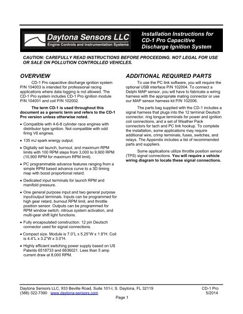
Installation <strong>Instructions</strong> for<br />
<strong>CD</strong>-1 <strong>Pro</strong> <strong>Capacitive</strong><br />
<strong>Discharge</strong> <strong>Ignition</strong> System<br />
CAUTION: CAREFULLY READ INSTRUCTIONS BEFORE PROCEEDING. NOT LEGAL FOR USE<br />
OR SALE ON POLLUTION CONTROLLED VEHICLES.<br />
OVERVIEW<br />
<strong>CD</strong>-1 <strong>Pro</strong> capacitive discharge ignition system<br />
P/N 104003 is intended for professional racing<br />
applications where data logging is not allowed. The<br />
<strong>CD</strong>-1 <strong>Pro</strong> system includes <strong>CD</strong>-1 <strong>Pro</strong> ignition module<br />
P/N 104001 and coil P/N 102002.<br />
The term <strong>CD</strong>-1 is used throughout this<br />
document as a generic term and refers to the <strong>CD</strong>-1<br />
<strong>Pro</strong> version unless otherwise noted.<br />
Compatible with 4-6-8 cylinder race engines with<br />
distributor type ignition. Not compatible with odd<br />
firing V6 engines.<br />
135 mJ spark energy output.<br />
Digitally set launch, burnout, and maximum RPM<br />
limits with 100 RPM steps from 3,000 to 9,900 RPM<br />
(10,900 RPM for maximum RPM limit).<br />
PC programmable advance features ranging from a<br />
simple RPM based advance curve to a 3D timing<br />
map with boost proportional retard.<br />
Dedicated input terminals for launch RPM and<br />
manifold pressure.<br />
One general purpose input and two general purpose<br />
input/output terminals. Inputs can be programmed for<br />
high gear retard, burnout RPM limit, and throttle<br />
position sensor. Outputs can be programmed for<br />
RPM window switch, nitrous system activation, and<br />
multi-gear shift light functions.<br />
Fully encapsulated construction. 12 pin Deutsch<br />
connector used for signal connections.<br />
Compact size. Module is 7.0”L x 5.25”W x 1.9”H. Coil<br />
is 4.4”L x 3.2”W x 3.0”H.<br />
Highly efficient switching power supply based on US<br />
Patents 6518733 and 6636021. Less than 5 amp<br />
current draw at 8,000 RPM.<br />
ADDITIONAL REQUIRED PARTS<br />
To use the PC link software, you will require the<br />
optional USB interface P/N 102004. To connect a<br />
Delphi MAP sensor, you will have to fabricate a wiring<br />
harness with the appropriate mating connector or use<br />
our MAP sensor harness kit P/N 102006.<br />
The parts bag supplied with the <strong>CD</strong>-1 includes a<br />
signal harness that plugs into the 12 terminal Deutsch<br />
connector, ring tongue terminals for power and ignition<br />
coil connections, and a set of Weather Pack<br />
connectors for tach and PC link hookup. To complete<br />
the installation, some applications may require<br />
additional wire, crimp terminals, fuses, switches, and<br />
relays. The Appendix includes a list of recommended<br />
parts and suppliers.<br />
Some applications utilize throttle position sensor<br />
(TPS) signal connections. You will require a vehicle<br />
wiring diagram to locate these signal connections.<br />
<strong>Daytona</strong> Sensors LLC, 933 Beville Road, Suite 101-I, S. <strong>Daytona</strong>, FL 32119<br />
<strong>CD</strong>-1 <strong>Pro</strong><br />
(386) 322-7390 www.daytona-sensors.com 5/2014<br />
Page 1
WIRING OVERVIEW<br />
Power Connections<br />
Heavy (12<br />
AWG) Red<br />
Heavy (12<br />
AWG) Black<br />
Battery+<br />
Ground<br />
<strong>Ignition</strong> Coil Primary Connections<br />
Connects to battery positive terminal. Do not connect to the<br />
alternator. If leads must be extended, add filter capacitor as<br />
shown in basic hookup diagrams.<br />
Connects to chassis ground.<br />
Orange Coil+ Connects to coil positive terminal<br />
Black Coil- Connects to coil negative terminal<br />
Deutsch Connector Signals<br />
Red (Pin 1)<br />
Blue (Pin 2)<br />
<strong>Ignition</strong><br />
Switch<br />
Launch RPM<br />
Limit<br />
Connects to ignition switch<br />
Orange (Pin 3) GPI1 General purpose input 1<br />
Connects to launch RPM limit circuit. Supplied 1N4007 diode<br />
must be installed if circuit includes a solenoid valve.<br />
Gray (Pin 4) GPIO2 General purpose input/output 2. Used for burnout RPM limit.<br />
Supplied 1N4007 diode must be installed if circuit includes a<br />
solenoid valve.<br />
Yellow (Pin 5) GPIO3 General purpose input/output 3<br />
Violet (Pin 6)<br />
Green (Pin 7)<br />
Pin 8<br />
Magnetic<br />
Trigger+<br />
Magnetic<br />
Trigger-<br />
Sensor<br />
Ground<br />
Connects to magnetic pickup distributor or crank trigger. If the<br />
magnetic trigger inputs are used, the module trigger input on<br />
pin 12 must be left open.<br />
Connects to magnetic pickup distributor or crank trigger. If the<br />
magnetic trigger inputs are used, the module trigger input on<br />
pin 12 must be left open.<br />
Connects to MAP sensor ground<br />
Pin 9 MAP Sensor Connects to 0-5V MAP sensor signal<br />
Pin 10 +5V Power Connects to MAP sensor power<br />
Brown (Pin 11) Tach/RS-232<br />
White (Pin 12)<br />
Module<br />
Trigger<br />
Connects to tach and optional USB interface<br />
Connects to trigger output from engine control module. If the<br />
module trigger input is used, the magnetic trigger inputs on<br />
pins 6 and 7 must be left open.<br />
<strong>Daytona</strong> Sensors LLC, 933 Beville Road, Suite 101-I, S. <strong>Daytona</strong>, FL 32119<br />
<strong>CD</strong>-1 <strong>Pro</strong><br />
(386) 322-7390 www.daytona-sensors.com 5/2014<br />
Page 2
1<br />
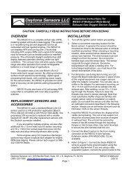
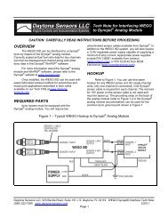
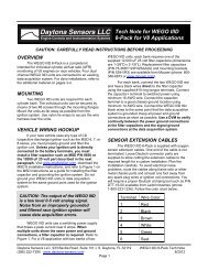
Figure 2 – Basic Magnetic Trigger Hookup<br />
DISTRIBUTOR<br />
WITH MAGNETIC<br />
PICKUP<br />
CRANK TRIGGER<br />
SYSTEM WITH<br />
MAGNETIC PICKUP<br />
<strong>CD</strong>-1 VIOLET MAG+<br />
<strong>CD</strong>-1 GREEN MAG-<br />
REFER TO INSTRUCTIONS<br />
FOR COMMON MAGNETIC<br />
TRIGGER COLOR CODES<br />
AMP CONNECTORS<br />
VIOLET (PIN 6) AND<br />
GREEN (PIN 7)<br />
TWISTED PAIR<br />
TACH<br />
+12V<br />
IGNITION SWITCH<br />
RED (PIN1)<br />
WEATHER PACK<br />
CONNECTORS<br />
FEMALE<br />
TERMINAL<br />
MALE<br />
TERMINAL<br />
RPM<br />
BROWN<br />
(PIN 11)<br />
TO OPTIONAL USB<br />
INTERFACE USED<br />
FOR PC LINK<br />
BLACK<br />
<strong>CD</strong>-1 IGNITION<br />
ORANGE<br />
OPTIONAL FILTER CAPACITOR REQUIRED<br />
IF POWER WIRES MUST BE EXTENDED<br />
TO BATTERY+<br />
RED<br />
<strong>CD</strong>-1 IGNITION COIL<br />
BLACK<br />
CHASSIS GROUND<br />
<strong>Daytona</strong> Sensors LLC, 933 Beville Road, Suite 101-I, S. <strong>Daytona</strong>, FL 32119<br />
<strong>CD</strong>-1 <strong>Pro</strong><br />
(386) 322-7390 www.daytona-sensors.com 5/2014<br />
Page 3
1<br />
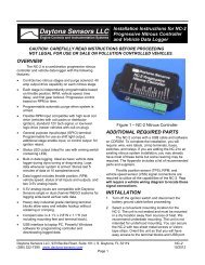
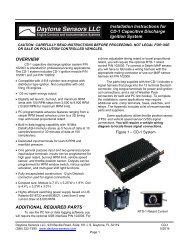
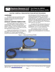
Figure 3 – Basic Module Trigger Hookup<br />
ENGINE<br />
CONTROL<br />
MODULE<br />
TRIGGER<br />
OUTPUT<br />
WHITE (PIN 12)<br />
WEATHER PACK<br />
CONNECTORS<br />
TACH<br />
+12V<br />
IGNITION SWITCH<br />
RED (PIN 1)<br />
FEMALE<br />
TERMINAL<br />
MALE<br />
TERMINAL<br />
RPM<br />
BROWN<br />
(PIN 11)<br />
TO OPTIONAL USB<br />
INTERFACE USED<br />
FOR PC LINK<br />
BLACK<br />
<strong>CD</strong>-1 IGNITION<br />
ORANGE<br />
OPTIONAL FILTER CAPACITOR REQUIRED<br />
IF POWER WIRES MUST BE EXTENDED<br />
TO BATTERY+<br />
RED<br />
<strong>CD</strong>-1 IGNITION COIL<br />
BLACK<br />
CHASSIS GROUND<br />
<strong>Daytona</strong> Sensors LLC, 933 Beville Road, Suite 101-I, S. <strong>Daytona</strong>, FL 32119<br />
<strong>CD</strong>-1 <strong>Pro</strong><br />
(386) 322-7390 www.daytona-sensors.com 5/2014<br />
Page 4
INSTALLATION<br />
1. Turn off the ignition switch and disconnect the<br />
battery ground cable before proceeding.<br />
2. Select a convenient mounting location for the <strong>CD</strong>-1<br />
module and coil. The <strong>CD</strong>-1 module is fully<br />
encapsulated and waterproof, but should be<br />
mounted in a dry location away from sources of<br />
heat. We recommend under dash mounting and<br />
using rubber shock mounts such as McMaster-Carr<br />
(www.mcmaster.com) P/N 9376K72. Orient the<br />
unit so that you will have easy access to the rotary<br />
switches. The <strong>CD</strong>-1 coil can be mounted in the<br />
engine compartment near the distributor.<br />
3. Refer to Figures 2 or 3 for basic hookup.<br />
WARNING: Do not cut the power or coil<br />
wires shorter than 12 inches. Doing so<br />
makes the unit impossible to test and<br />
will void the warranty.<br />
4. Power connections. Race vehicles should be<br />
equipped with a battery disconnect switch.<br />
Connect the 12 AWG red wire to the battery<br />
disconnect switch or the battery cable at the starter<br />
solenoid. If the battery is mounted in the trunk, a<br />
filter capacitor is required and minimum 12 AWG<br />
wire should be used for the connection to the<br />
disconnect switch or power block. You can use a<br />
10000 UF 25V electrolytic capacitor such as our<br />
P/N 102007 capacitor kit or Mouser<br />
(www.mouser.com) P/N 539-CGS103U025RC3<br />
and bracket P/N 539-VR3A. Connect the 12 AWG<br />
black wire to chassis ground near the engine,<br />
preferably where the battery ground cable is<br />
attached. Do not extend the black ground wire.<br />
Verify that the engine is properly grounded to the<br />
chassis. Separate ground straps are<br />
recommended for each cylinder head.<br />
5. <strong>Ignition</strong> switch connection. Connect the red wire<br />
from Deutsch connector pin 1 to the ignition switch<br />
as shown.<br />
6. Trigger signal connections. The violet/green<br />
magnetic pickup cable is supplied with an AMP<br />
connector that will mate with common MSD<br />
magnetic pickup distributors and crank trigger<br />
systems. For other magnetic pickups, cut off the<br />
connector and refer to the color code table below.<br />
For module triggered applications from engine<br />
control modules such as Haltech or Motec, the <strong>CD</strong>-<br />
1 requires a 0-12V square wave signal and fires on<br />
the rising edge. The module trigger input on pin 12<br />
is tolerant of high voltage pulses and has an<br />
internal 150 ohm pull-up resistor to +12V.<br />
Magnetic Trigger Color Codes<br />
System Mag- Mag+<br />
Accel/Chrysler<br />
Distributor<br />
Black Orange/White<br />
Accel Crank<br />
Trigger<br />
Moroso Crank<br />
Trigger<br />
MSD Crank<br />
Trigger<br />
MSD/Ford<br />
Distributor<br />
Black<br />
White<br />
Green/Black<br />
Violet<br />
White<br />
Black<br />
Violet/Orange<br />
Orange<br />
GM Distributor Green White<br />
7. Coil connections. Connect the black and orange<br />
coil wires to the ignition coil as shown.<br />
DANGER: High voltage is present at the<br />
coil primary and secondary terminals<br />
whenever the ignition switch is on. Do<br />
not touch or connect any test<br />
equipment to the coil terminals.<br />
8. Tach connection. Use the supplied Weather Pack<br />
connectors as shown to connect the brown wire<br />
from Deutsch connector pin 11 to the vehicle tach<br />
as shown. The tach output is also used for PC link<br />
communications before the engine is started by<br />
means of an optional USB interface P/N 102004.<br />
When the engine is running an industry standard<br />
0-12V square wave signal appears on the tach<br />
output with one tach pulse per trigger event. The<br />
rising edge of tach pulse is synchronized with the<br />
trigger event. This tach output is compatible with all<br />
aftermarket tachometers such as Autometer and<br />
can also be used to trigger other RPM activated<br />
accessories.<br />
9. Application specific signal connections. Refer<br />
to the following sections and Figures 4-10.<br />
10. Completing the installation. Remove any<br />
unused wires from the Deutsch connector and<br />
install supplied terminal seals. Reconnect the<br />
battery. Set the <strong>CD</strong>-1 switches and upload any<br />
required setup program. Start engine and check<br />
timing. If timing has changed significantly, MAG+<br />
and MAG- may be reversed.<br />
<strong>Daytona</strong> Sensors LLC, 933 Beville Road, Suite 101-I, S. <strong>Daytona</strong>, FL 32119<br />
<strong>CD</strong>-1 <strong>Pro</strong><br />
(386) 322-7390 www.daytona-sensors.com 5/2014<br />
Page 5
1<br />
1<br />
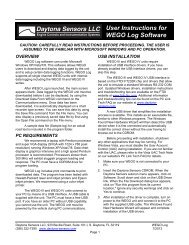
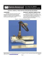
Figure 4 – MAP Sensor Hookup<br />
DELPHI<br />
MAP<br />
SENSOR<br />
BLACK<br />
A<br />
WHITE<br />
B<br />
C RED<br />
PIN<br />
A<br />
B<br />
C<br />
SIGNAL<br />
GROUND<br />
MAP OUTPUT<br />
+5V POWER<br />
10<br />
9<br />
8<br />
RED<br />
WHITE<br />
BLACK<br />
PIN SIGNAL<br />
8 SENSOR GROUND<br />
9 MAP INPUT<br />
10 +5V POWER<br />
<strong>CD</strong>-1 IGNITION<br />
Figure 5 – Automatic Transmission RPM Limit Switch Hookup<br />
SWITCHED +12V<br />
LINE LOCK<br />
OR BRAKE<br />
SWITCH<br />
GRAY<br />
SUPPLIED<br />
1N4007<br />
DIODE<br />
LINE LOCK<br />
SOLENOID<br />
VALVE<br />
GROUND<br />
4<br />
2<br />
BLUE<br />
SWITCHED +12V<br />
TRANS BRAKE<br />
TRIGGER<br />
SWITCH<br />
<strong>CD</strong>-1 IGNITION<br />
PIN SIGNAL<br />
2 LAUNCH RPM LIMIT<br />
4 GPIO2 (BURNOUT RPM LIMIT)<br />
SUPPLIED<br />
1N4007<br />
DIODE<br />
WARNING: FAILURE TO<br />
INSTALL DIODES WILL<br />
DAMAGE THE <strong>CD</strong>-1 AND<br />
VOID THE WARRANTY<br />
TRANS<br />
BRAKE<br />
SOLENOID<br />
VALVE<br />
GROUND<br />
<strong>Daytona</strong> Sensors LLC, 933 Beville Road, Suite 101-I, S. <strong>Daytona</strong>, FL 32119<br />
<strong>CD</strong>-1 <strong>Pro</strong><br />
(386) 322-7390 www.daytona-sensors.com 5/2014<br />
Page 6
1<br />
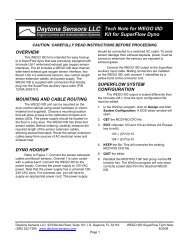
Figure 6 – Manual Transmission RPM Limit Switch Hookup<br />
SWITCHED +12V<br />
WARNING: FAILURE TO<br />
INSTALL DIODE WILL<br />
DAMAGE THE <strong>CD</strong>-1 AND<br />
VOID THE WARRANTY<br />
LINE LOCK<br />
SWITCH<br />
BLUE<br />
SUPPLIED<br />
1N4007<br />
DIODE<br />
LINE LOCK<br />
SOLENOID<br />
VALVE<br />
GROUND<br />
2<br />
4<br />
30 85<br />
<strong>CD</strong>-1 IGNITION<br />
SWITCHED +12V<br />
CLUTCH<br />
SWITCH<br />
87 86<br />
12V<br />
RELAY<br />
GROUND<br />
PIN SIGNAL<br />
2 LAUNCH RPM LIMIT<br />
4 GPIO2 (BURNOUT RPM LIMIT)<br />
GRAY<br />
BURNOUT<br />
RPM LIMIT<br />
SWITCH<br />
SWITCHED +12V<br />
<strong>Daytona</strong> Sensors LLC, 933 Beville Road, Suite 101-I, S. <strong>Daytona</strong>, FL 32119<br />
<strong>CD</strong>-1 <strong>Pro</strong><br />
(386) 322-7390 www.daytona-sensors.com 5/2014<br />
Page 7
1<br />
1<br />
Figure 7 – Nitrous Oxide System Hookup<br />
SWITCHED +12V<br />
BATTERY+<br />
ARMING<br />
SWITCH<br />
50 AMP<br />
MAXI FUSE<br />
4<br />
GRAY<br />
85 30<br />
86 87<br />
12V<br />
RELAY<br />
NITROUS<br />
SOLENOID<br />
3<br />
FUEL<br />
SOLENOID<br />
<strong>CD</strong>-1 IGNITION<br />
GROUND<br />
PIN SIGNAL<br />
3 GPI1 (NOS ENABLE)<br />
4 GPIO2 (NOS TRIGGER)<br />
ORANGE<br />
WIDE OPEN<br />
THROTTLE<br />
SWITCH<br />
THROTTLE<br />
POSITION<br />
SENSOR<br />
Figure 8 – Additional GPI1 Hookup Options<br />
3<br />
ORANGE<br />
SUPPLIED<br />
1N4007<br />
DIODE<br />
DIGITAL<br />
RETARD<br />
MODE<br />
HIGH GEAR<br />
RETARD<br />
SWITCH<br />
SWITCHED +12V<br />
<strong>CD</strong>-1 IGNITION<br />
FOR DIGITAL RETARD, DIODE IS<br />
REQUIRED IF AN INDUCTIVE DEVICE<br />
SUCH AS A SOLENOID IS PART OF THE<br />
CIRCUIT. WARNING: FAILURE TO<br />
INSTALL REQUIRED DIODE WILL<br />
DAMAGE THE <strong>CD</strong>-1 AND VOID THE<br />
WARRANTY<br />
<strong>Daytona</strong> Sensors LLC, 933 Beville Road, Suite 101-I, S. <strong>Daytona</strong>, FL 32119<br />
<strong>CD</strong>-1 <strong>Pro</strong><br />
(386) 322-7390 www.daytona-sensors.com 5/2014<br />
Page 8
1<br />
1<br />
Figure 9 – Additional GPIO2 Hookup Options<br />
SWITCHED +12V<br />
BATTERY+<br />
OPTIONAL<br />
ARMING<br />
SWITCH<br />
FUSE<br />
4 GRAY 85 30<br />
RPM WINDOW<br />
12V<br />
SWITCH MODE RELAY<br />
86 87<br />
<strong>CD</strong>-1 IGNITION<br />
LOAD<br />
GROUND<br />
Figure 10 – GPIO3 Hookup Options<br />
SHIFT LIGHT MODE<br />
SWITCHED<br />
+12V LED SHIFT LIGHT<br />
(AUTOMETER 5330)<br />
+ -<br />
5 YELLOW 85 30<br />
SWITCHED +12V<br />
BATTERY+<br />
OPTIONAL<br />
ARMING<br />
SWITCH<br />
FUSE<br />
<strong>CD</strong>-1 IGNITION<br />
RPM WINDOW<br />
SWITCH MODE<br />
86 87<br />
12V<br />
RELAY<br />
LOAD<br />
GROUND<br />
<strong>Daytona</strong> Sensors LLC, 933 Beville Road, Suite 101-I, S. <strong>Daytona</strong>, FL 32119<br />
<strong>CD</strong>-1 <strong>Pro</strong><br />
(386) 322-7390 www.daytona-sensors.com 5/2014<br />
Page 9
MAP Sensor Hookup<br />
A manifold absolute pressure (MAP) sensor is required<br />
for boost timing retard mode and all applications that<br />
use a 3D timing table uploaded with the PC link.<br />
The optional MAP sensor harness includes mating<br />
connector shells for Delphi 1 bar, 2 bar, and 3 bar MAP<br />
sensors (refer to the Appendix for recommended MAP<br />
sensor part numbers). Select the connector shell with<br />
the appropriate indexing features for your MAP sensor.<br />
Connect the ground, MAP signal, and +5V power wires<br />
as shown in Figure 4.<br />
Automatic Transmission RPM Limit<br />
Switch Hookup<br />
Figure 5 shows typical hookup of the line lock and<br />
trans brake solenoid valves for automatic transmission<br />
vehicles.<br />
1. Line lock and burnout RPM limit. Skip ahead if<br />
this feature is not used. The line lock is active<br />
during burnout and used to select the burnout<br />
RPM limit. GPIO2 must be programmed for<br />
burnout RPM limit mode by means of the PC link<br />
(refer to page 19 for details). Burnout RPM limit is<br />
selected when GPIO2 is at +12V.<br />
2. Trans brake and launch RPM limit. The trans<br />
brake is active before launching and used to select<br />
the launch RPM limit set on the <strong>CD</strong>-1 switches.<br />
The launch RPM limit is selected when the launch<br />
RPM limit input is at +12V.<br />
WARNING: Failure to install the diodes<br />
shown in Figure 5 will damage the <strong>CD</strong>-1<br />
and void the warranty.<br />
Manual Transmission RPM Limit<br />
Switch Hookup<br />
Figure 6 shows typical hookup of the line lock and<br />
burnout RPM limit switch for manual transmission<br />
vehicles.<br />
1. Burnout RPM limit. Skip ahead if this feature is<br />
not used. A switch is used to select the burnout<br />
RPM limit. GPIO2 must be programmed for<br />
burnout RPM limit mode by means of the PC link<br />
(refer to page 19 for details). Burnout RPM limit is<br />
selected when GPIO2 is at +12V<br />
2. Line lock and launch RPM limit. The line lock is<br />
active before launching and used to select the<br />
launch RPM limit set on the <strong>CD</strong>-1 switches. The<br />
hookup shown in Figure 6 uses a relay to hold the<br />
line lock on until the clutch is released. A normally<br />
open momentary pushbutton switch is used to<br />
initially set the line lock. The clutch switch is<br />
normally open and closes when the clutch pedal is<br />
down. The launch RPM limit is selected when the<br />
launch RPM limit input is at +12V.<br />
WARNING: Failure to install the diode<br />
shown in Figure 6 will damage the <strong>CD</strong>-1<br />
and void the warranty.<br />
Nitrous Oxide System (NOS) Hookup<br />
Figure 7 shows typical hookup of the single stage NOS<br />
controlled by the <strong>CD</strong>-1. The NOS is triggered based on<br />
throttle position and an RPM window. When the NOS<br />
is triggered on, timing can be automatically retarded up<br />
to 10 degrees. The use this capability, GPI1 must be<br />
programmed for NOS enable mode and GPIO2 must<br />
be programmed for NOS trigger mode by means of the<br />
PC link (refer to pages 18-19 for details). Either a wide<br />
open throttle switch or throttle position sensor can be<br />
used for NOS enable.<br />
1. Wide open throttle switch for NOS enable. The<br />
switch is normally open and closes at wide open<br />
throttle. This arrangement is typically used with<br />
carbureted vehicles. +12V for the wide open<br />
throttle switch is supplied by a separate NOS<br />
arming switch. +12V on GPI1 enables the NOS.<br />
2. Throttle position sensor (TPS) for NOS enable.<br />
Vehicles with electronic fuel injection typically have<br />
a TPS with 0-5V signal output. Refer to the vehicle<br />
wiring diagram for details. You can check the TPS<br />
signal with a DVM. The threshold TPS voltage for<br />
enabling the NOS is programmed by means of the<br />
PC link.<br />
3. NOS wiring. The arming switch should be<br />
connected to switched +12V so that the NOS<br />
cannot be armed when ignition power is off. A relay<br />
with a minimum 40 amp rating is required. If your<br />
nitrous system uses large solenoid valves, you<br />
should use the heavy duty P&B/Tyco VF7 series<br />
70 amp relay listed in the Appendix. The use of a<br />
50 amp fuse block such as the Littlefuse Maxi Fuse<br />
series listed in the Appendix is recommended.<br />
Power connections from the fuse block must go<br />
direct to the battery positive terminal or battery<br />
disconnect switch. The ground connection from the<br />
solenoids must go to a chassis ground stud or<br />
direct to the battery negative terminal. Use 12 or<br />
14 AWG wire. Keep power and ground<br />
connections as short as possible.<br />
<strong>Daytona</strong> Sensors LLC, 933 Beville Road, Suite 101-I, S. <strong>Daytona</strong>, FL 32119<br />
<strong>CD</strong>-1 <strong>Pro</strong><br />
(386) 322-7390 www.daytona-sensors.com 5/2014<br />
Page 10
Additional GPI1 Hookup Options<br />
Figure 8 shows additional hookup options for GPI1<br />
modes that can be programmed by means of the PC<br />
link when the GPI1 input is not used by the<br />
configuration shown in Figure 7. Refer to page 18 for<br />
programming details.<br />
Digital retard mode. This can be used as a high gear<br />
retard or retard function for a nitrous system. Connect<br />
a switch or relay contact to +12V to GPI1. Timing is<br />
retarded up to 10 degrees when GPI1 is at +12V.<br />
WARNING: If GPI1 is used as a digital<br />
input and some inductive device such<br />
as a solenoid is also part of the circuit,<br />
a diode is required to protect the input<br />
from transients. Failure to install the<br />
required diode will damage the <strong>CD</strong>-1<br />
and void the warranty.<br />
Additional GPIO2 Hookup Options<br />
Figure 9 shows additional hookup options for GPIO2<br />
modes that can be programmed by means of the PC<br />
link when the GPIO2 terminal is not used by one of the<br />
configurations shown in Figures 5-7. Refer to page 19<br />
for programming details.<br />
RPM window switch mode. Connect a relay as<br />
shown to control a load. You can connect an optional<br />
arming switch as shown. For direct battery power<br />
connections, you should also install a fuse. Refer to the<br />
Appendix for recommended relays and fuses.<br />
GPIO3 Hookup Options<br />
Figure 10 shows hookup options for GPIO3 modes that<br />
can be programmed by means of the PC link. Refer to<br />
page 19 for programming details.<br />
1. Shift light mode. Connect an LED shift light such<br />
as Autometer (www.autometer.com) P/N 5330 as<br />
shown. Maximum current draw should not exceed<br />
1 amp.<br />
2. RPM window switch mode. Connect a relay as<br />
shown to control a load. You can connect an<br />
optional arming switch as shown. For direct battery<br />
power connections, you should also install a fuse.<br />
Refer to the Appendix for recommended relays and<br />
fuses.<br />
SWITCH SETTINGS AND STATUS<br />
LED<br />
The left end panel of the <strong>CD</strong>-1 has five rotary<br />
switches used to set RPM limits and operating modes<br />
and a status LED. The status LED will illuminate when<br />
the ignition switch is turned on. If a fault condition<br />
occurs, such as a DC/DC converter (internal high<br />
voltage power supply used to charge the capacitor)<br />
fault or loss of trigger signal, the status LED will blink.<br />
Launch RPM Limit Switch Settings<br />
00 RPM limit disabled<br />
01 RPM limit and multi-spark disabled<br />
02 RPM limit, multi-spark, and timing functions<br />
disabled<br />
03-04 Reserved (not used)<br />
05 Boot load mode (used by factory to<br />
reprogram <strong>CD</strong>-1 module)<br />
06-99 Launch RPM limit setting X100 (i.e. switch<br />
setting 35 = 3,500 RPM)<br />
Maximum RPM Limit Switch Settings<br />
The maximum RPM limit setting is offset 1,000<br />
RPM to allow two switches to set the value between<br />
1,000 and 10,900 RPM<br />
00-99 Maximum RPM limit setting X100 + 1000 (i.e.<br />
switch setting 75 = 8,500 RPM and 99 =<br />
10,900 RPM)<br />
Mode Switch Settings<br />
0 8 cylinder engine and normal operation<br />
1 6 cylinder engine and normal operation<br />
2 4 cylinder engine and normal operation<br />
3-9 Reserved (not used)<br />
Mode switch settings 0-2 are used during normal<br />
operation of the <strong>CD</strong>-1 and allow full functionality of any<br />
selections made with the PC Link software.<br />
<strong>Daytona</strong> Sensors LLC, 933 Beville Road, Suite 101-I, S. <strong>Daytona</strong>, FL 32119<br />
<strong>CD</strong>-1 <strong>Pro</strong><br />
(386) 322-7390 www.daytona-sensors.com 5/2014<br />
Page 11
Figure 11 – Switches and Status LED<br />
hookup shown in Figure 2 will also require a tach<br />
adapter.<br />
9 0 1<br />
2<br />
3 4<br />
7 8<br />
5 6<br />
9 0 1<br />
2<br />
3 4<br />
7 8<br />
LAUNCH<br />
RPM LIMIT<br />
X100<br />
5 6<br />
9 0 1<br />
2<br />
3 4<br />
7 8<br />
5 6<br />
9 0 1<br />
2<br />
3 4<br />
7 8<br />
5 6<br />
MAXIMUM<br />
RPM LIMIT<br />
X100 + 1000<br />
9 0 1<br />
2<br />
3 4<br />
7 8<br />
5 6<br />
MODE<br />
STATUS<br />
PN 104001<br />
SPARK PLUGS AND WIRES<br />
To avoid electrical noise that may interfere with<br />
the <strong>CD</strong>-1 or other onboard computer and radio<br />
equipment, resistor spark plugs are recommended and<br />
spiral core RFI/EMI suppression type spark plug wires<br />
are required. Optimum spark plug gap is .045" for<br />
normally aspirated engines. Engines with high boost<br />
levels may require a smaller spark plug gap. Do not<br />
use solid copper or high resistance carbon core spark<br />
plug wires. Optimum spark plug wire resistance is 50-<br />
500 ohms per foot, such as Taylor Vertex<br />
(www.taylorvertex.com) ThunderVolt 50 or 8.2mm<br />
spiral core.<br />
APPLICATION ISSUES WITH<br />
VINTAGE RACE VEHICLES<br />
Application issues may occur with vintage race<br />
vehicles, especially 1970s and earlier Ford, GM, and<br />
Mopar vehicles that have original equipment charging<br />
systems. General information is given below. For<br />
assistance with specific applications, please contact<br />
our tech support.<br />
1. Tach hookup. Some original equipment tachs<br />
require a high voltage pulse and will require a<br />
commercially available tach adapter. GM vehicles,<br />
including all models with HEI coil-in-cap, have an<br />
inline tach filter. Disconnect the filter, trace the wire<br />
from the tach, and connect it to the <strong>CD</strong>-1 as shown<br />
in Figures 1 or 2.<br />
2. <strong>Ignition</strong> run-on. If the engine continues to run<br />
after the ignition switch is turned off, current is<br />
leaking back into the <strong>CD</strong>-1 through the charging<br />
system indicator lamp. GM or Ford models with an<br />
external voltage regulator will require installation of<br />
a diode.<br />
3. Import vehicles with electronic fuel injection or<br />
a fuel pump cut-out relay. Some systems require<br />
a tach signal with a high voltage pulse and will<br />
require a commercially available tach adapter.<br />
Some Japanese vehicles using the module trigger<br />
TROUBLESHOOTING<br />
Did the engine run properly before installation of<br />
the <strong>CD</strong>-1? If not, remove the <strong>CD</strong>-1, reinstall the original<br />
ignition system and then find and correct the original<br />
problem. Did the <strong>CD</strong>-1 function correctly before the<br />
problem occurred? If the answer is yes, did you<br />
change anything that may have affected it? To isolate<br />
the problem, go back to the last setup that was OK. If<br />
the engine will not start, runs intermittently, or misfires,<br />
use the following check list steps:<br />
Status LED Doesn’t Illuminate<br />
If the status LED doesn't illuminate after the<br />
ignition switch is turned on, check power and ground<br />
connections. Use a volt meter to verify +12V at the<br />
battery+ and ignition switch wires at the <strong>CD</strong>-1 with the<br />
ignition switch in both the run and start positions. The<br />
<strong>CD</strong>-1 requires a minimum of +9V when the ignition<br />
switch is first turned on. During cranking, the unit will<br />
continue to operate down to +4.5V.<br />
Engine Will Not Start<br />
If the status LED illuminates when the ignition<br />
switch is turned on but the engine will not start, verify<br />
that the status LED blinks while the engine is cranking.<br />
If the status LED doesn't blink during cranking, the unit<br />
is not getting a trigger signal. Verify that trigger signal<br />
wiring is not shorted together or to ground. If the status<br />
LED blinks, but engine will not start, recheck coil<br />
primary connections or replace coil.<br />
Import vehicles: if the engine momentarily starts<br />
and then dies, a fuel pump cut-out relay may not be<br />
operating properly. Please contact our tech support.<br />
Spark Testing<br />
K-D Tools HEI ignition test plug P/N 2756 is<br />
recommended for spark testing. Attach the alligator clip<br />
on the test plug to chassis ground and fabricate a short<br />
section of spark plug wire to connect the test plug to<br />
the coil.<br />
Intermittent Operation or Misfire at High RPM<br />
1. Misfire at high RPM is usually not an electrical<br />
problem with the <strong>CD</strong>-1. Common causes include:<br />
coil failure or arcing at spark plug boots or within<br />
the distributor.<br />
2. For vehicles without an alternator, low battery<br />
voltage may cause misfire at high RPM. Verify that<br />
<strong>Daytona</strong> Sensors LLC, 933 Beville Road, Suite 101-I, S. <strong>Daytona</strong>, FL 32119<br />
<strong>CD</strong>-1 <strong>Pro</strong><br />
(386) 322-7390 www.daytona-sensors.com 5/2014<br />
Page 12
the battery is fully charged or try replacing the<br />
battery.<br />
3. To avoid electrical noise problems, route magnetic<br />
trigger wiring away from any coil or spark plug<br />
wires. Use only spiral core spark plug wires. Do not<br />
use solid copper core or carbon core resistance<br />
wires.<br />
4. Check for broken, loose or corroded connections.<br />
Verify correct air gap for magnetic pickup. Check<br />
distributor for loose, missing, or jammed parts in<br />
advance mechanism.<br />
5. Verify that spark plugs are proper type, gap size,<br />
and heat range.<br />
6. Replace spark plugs, spark plug wires, and<br />
distributor rotor and cap.<br />
<strong>Daytona</strong> Sensors LLC, 933 Beville Road, Suite 101-I, S. <strong>Daytona</strong>, FL 32119<br />
<strong>CD</strong>-1 <strong>Pro</strong><br />
(386) 322-7390 www.daytona-sensors.com 5/2014<br />
Page 13
<strong>CD</strong>-1 SOFTWARE OVERVIEW<br />
The PC Link <strong>CD</strong> <strong>Pro</strong> software allows you to set<br />
module parameters that control overall operation of the<br />
system and override certain switch settings, program<br />
the functions of the general purpose input/output<br />
(GPIO) terminals, and program advance curves.<br />
Use of the software programs is optional and not<br />
required for basic operation of the <strong>CD</strong>-1 system. If you<br />
are not planning on using the software, you can skip<br />
the rest of the material in this instruction manual.<br />
The <strong>CD</strong>-1 <strong>Pro</strong> version cannot be used with the<br />
software for the standard <strong>CD</strong>-1 version that includes<br />
data logging capability. If you attempt to communicate<br />
with a <strong>CD</strong>-1 <strong>Pro</strong> unit using the standard PC Link <strong>CD</strong> or<br />
<strong>CD</strong> Log software, an error message will appear and<br />
communications will be aborted.<br />
PC REQUIREMENTS<br />
The <strong>CD</strong>-1 connects to your PC by means of an<br />
optional USB interface P/N 102004. The PC must have<br />
a free USB port. If you have an older PC without USB<br />
capability, you cannot use the <strong>CD</strong>-1 software.<br />
We recommend a laptop PC with Pentium<br />
processor and super VGA display (SVGA with 1024 x<br />
768 pixel resolution) running Windows XP/Vista/7.<br />
Data chart display is graphics intensive and a high<br />
speed Pentium processor is recommended.<br />
<strong>Pro</strong>cessors slower than 300 MHz will exhibit sluggish<br />
program loading and response. The PC must have a<br />
<strong>CD</strong>ROM drive for program loading.<br />
PC Link <strong>CD</strong> <strong>Pro</strong> software includes print<br />
commands to print downloaded data. The program has<br />
been tested with Hewlett-Packard laser and inkjet<br />
printers and Epson inkjet printers. We recommend<br />
using a color inkjet printer.<br />
USB INSTALLATION<br />
The USB interface for the <strong>CD</strong>-1 is based on the<br />
FTDI FT232R chip and drivers that allow the unit to<br />
emulate a standard Windows RS-232 COM port.<br />
Updated Windows drivers, installation instructions and<br />
troubleshooting tips are available on the FTDI website<br />
at www.ftdichip.com. Additional information and<br />
troubleshooting tips can be found on the PC Link Tech<br />
FAQ on our website at www.daytona-sensors.com.<br />
A new USB driver that simplifies the installation<br />
process is available. This installs as an executable file,<br />
similar to other Windows programs. The Windows<br />
Found New Hardware Wizard will then detect the USB<br />
device when it is first connected and automatically<br />
install the correct driver without the user having to<br />
browse out to the <strong>CD</strong>ROM.<br />
Before proceeding with installation, shutdown<br />
any other applications that may be running. For<br />
Windows Vista, you must disable the User Account<br />
Control (UAC) during installation. If you are not familiar<br />
with the UAC, please refer to the Vista UAC Tech Note<br />
on our website's PC Link Tech FAQ for details.<br />
1. Make sure your USB interface is not connected to<br />
your PC. Please note that the USB interface does<br />
not need to be connected to the <strong>CD</strong>-1 during the<br />
USB installation process.<br />
2. Insert the <strong>Daytona</strong> Sensors <strong>CD</strong>ROM. When the<br />
<strong>Daytona</strong> Sensors autorun menu appears, click on<br />
Software. Scroll down and click on the USB Driver<br />
link. When the File Download dialog box appears,<br />
click on "Run this program from its current<br />
location." Ignore any security warnings and click on<br />
Yes to continue.<br />
3. After installation of the driver is complete, connect<br />
the USB interface to the PC with the supplied USB<br />
cable. The Windows Found New Hardware Wizard<br />
will appear and complete installation of the USB<br />
interface.<br />
COM Port Configuration<br />
After completing the installation steps outlined<br />
above, you must configure the new COM port using<br />
Device Manager.<br />
1. Click Start, Settings, Control Panel, System,<br />
Hardware, and then Device Manager. Scroll down<br />
to Ports (COM and LPT).<br />
2. The new USB interface will as appear as USB<br />
Serial Port. Click on this new port.<br />
3. Click on the Port Settings tab.<br />
4. Click on Advanced. In most cases the wizard will<br />
have installed your new USB interface as COM5.<br />
Note the COM port number assigned for your<br />
system. For optimum performance, you should<br />
also change the BM Options Latency Timer to 2<br />
msec as shown in the Figure 12.<br />
5. Once you have configured a COM port number for<br />
your new unit, make sure that you use this same<br />
COM port selection in the <strong>CD</strong>-1 software by using<br />
the Port Setup command from the<br />
Communications menu.<br />
<strong>Daytona</strong> Sensors LLC, 933 Beville Road, Suite 101-I, S. <strong>Daytona</strong>, FL 32119<br />
<strong>CD</strong>-1 <strong>Pro</strong><br />
(386) 322-7390 www.daytona-sensors.com 5/2014<br />
Page 14
Figure 12 – COM Port Configuration<br />
SOFTWARE INSTALLATION<br />
The software is supplied on <strong>CD</strong>ROM media or in<br />
the form of a compressed file downloaded from our<br />
website. The installation process uses InstallShield.<br />
This industry standard installer is based the new<br />
Microsoft Windows Installer service that greatly<br />
reduces potential problems such as version conflicts<br />
and allows for application self-repair.<br />
Before proceeding with installation, shutdown any<br />
other applications that may be running. For Windows<br />
Vista, you must disable the User Account Control<br />
(UAC) during installation. If you are not familiar with the<br />
UAC, please refer to the Vista UAC Tech Note on our<br />
website's Tech FAQ for details.<br />
Use the Windows Explorer or the Run command<br />
from the Windows Start Menu to launch setup.exe in the<br />
PC_Link_<strong>CD</strong>_<strong>Pro</strong> folder on the <strong>CD</strong>ROM or the<br />
setup.exe file downloaded from our website. InstallShield<br />
will install the software in an appropriate folder under<br />
<strong>Pro</strong>gram Files.<br />
Once InstallShield has completed the<br />
installation, PC Link <strong>CD</strong> <strong>Pro</strong> will appear on the<br />
Windows Start Menu. You can then launch it just as<br />
you would any other Windows program.<br />
The program requires the Monospace 821 BT<br />
fixed pitch printer font in order to properly align<br />
columns when printing. The Monospace 821 BT font is<br />
included in the distribution media and automatically<br />
copied to your Windows Fonts folder during<br />
installation. A backup copy is also placed in the<br />
program folder. If you accidentally delete this font, use<br />
the Install New Font command from the Fonts folder<br />
File menu. The filename associated with Monospace<br />
821 BT is monos.ttf.<br />
PC LINK <strong>CD</strong> PRO SOFTWARE<br />
The brown tachometer wire (Deutsch connector<br />
pin 11) from the <strong>CD</strong>-1 is used connect to the USB<br />
interface. Mating single pin Packard Weather Pack<br />
connectors are supplied with the <strong>CD</strong>-1 to facilitate<br />
disconnecting the brown wire from the vehicle<br />
tachometer and connecting it to the USB interface as<br />
shown in Figures 1 and 2. PC communications is<br />
possible when the ignition is turned on and the engine<br />
has not yet been started. Once the engine is started,<br />
the brown wire resumes its normal function of driving<br />
the tachometer. Note that no damage occurs if the<br />
engine is inadvertently started while the USB interface<br />
is connected.<br />
After PC Link <strong>CD</strong> <strong>Pro</strong> is launched, the main<br />
screen appears blank. You have three options for<br />
obtaining setup data for editing. You can open a<br />
previously saved setup file by using the Open Table<br />
command on the File menu. You can create a new<br />
setup file by using (as applicable) the Edit Module<br />
Parameters and Edit GPIO Parameters commands<br />
from the Edit menu and the New Timing Table<br />
command on the File menu. You can also download<br />
data from an attached <strong>CD</strong>-1 module by using the<br />
Download From EEPROM command on the<br />
Communications menu.<br />
Note that setup files use a .tbl extension. You<br />
should create a separate folder to store these files.<br />
If you have enabled a 2D or 3D timing table<br />
under module parameters, you can use the Edit Timing<br />
Table command from the Edit menu. You can edit the<br />
timing table data by clicking on and dragging individual<br />
points on the chart display or you can directly edit<br />
numeric data on the spreadsheet grid.<br />
Once the appropriate parameters and timing<br />
table data have been entered, you can print the data<br />
using the Print Parameters and Timing Table<br />
command on the Print Menu. You can save the edited<br />
setup file by using the Save Table command on the<br />
File menu.<br />
You can upload the setup data to an attached<br />
<strong>CD</strong>-1 module by using the Upload to EEPROM<br />
command on the Communications menu.<br />
A setup file (<strong>CD</strong>1_Sample.tbl) is included in the<br />
program folder.<br />
DOWNLOADING DATA FROM<br />
EEPROM<br />
Connect the USB interface. An adapter harness<br />
is supplied with the USB interface. Connect the<br />
<strong>Daytona</strong> Sensors LLC, 933 Beville Road, Suite 101-I, S. <strong>Daytona</strong>, FL 32119<br />
<strong>CD</strong>-1 <strong>Pro</strong><br />
(386) 322-7390 www.daytona-sensors.com 5/2014<br />
Page 15
alligator clip on the black wire to ground and the<br />
Packard Weather Pack connector to the brown tach<br />
wire from the <strong>CD</strong>-1 wire harness. If the tach wire is not<br />
equipped with a Weather Pack connector, you can use<br />
the supplied brown jumper wire with an alligator clip to<br />
make the required connection. Set the switch on the<br />
USB interface to the "A" position. Turn the ignition<br />
switch on to provide power to the <strong>CD</strong>-1. Do not start<br />
the engine.<br />
When launched for the first time, the program<br />
uses COM1 as the default port. In most cases, you will<br />
have configured the USB interface to use a different<br />
COM port, such as COM5. Use the Port Setup<br />
command on the Communications menu to select the<br />
correct COM port. The program will remember the new<br />
port setup.<br />
Download data by using the Download From<br />
EEPROM command on the Communications menu.<br />
If the download process is successful, the<br />
module parameters are displayed. You can then edit<br />
setup data as explained in subsequent sections.<br />
Figure 13 – Module Parameters<br />
<strong>CD</strong>-1 units are shipped from the factory with<br />
default parameters and timing tables loaded into<br />
EEPROM memory. If you have never uploaded any<br />
custom setup file to EEPROM memory, these defaults<br />
are what you will see.<br />
MODULE PARAMETERS<br />
Module parameters are displayed in a dialog box<br />
by using the Edit Module Parameters command on the<br />
Edit menu. Module parameters control the overall<br />
operation of the <strong>CD</strong>-1 unit.<br />
When PC Link <strong>CD</strong> <strong>Pro</strong> is first started, default<br />
module parameters are loaded. Module parameters<br />
are updated whenever you download data from a <strong>CD</strong>-1<br />
unit or open a setup file. Module parameters are saved<br />
along with the GPIO parameters and timing table data<br />
when you save a setup file. Always check the<br />
module parameters before uploading data to the<br />
<strong>CD</strong>-1.<br />
<strong>Daytona</strong> Sensors LLC, 933 Beville Road, Suite 101-I, S. <strong>Daytona</strong>, FL 32119<br />
<strong>CD</strong>-1 <strong>Pro</strong><br />
(386) 322-7390 www.daytona-sensors.com 5/2014<br />
Page 16
General Options<br />
Disable RPM Limit - all RPM limit functions are<br />
disabled (including any fixed maximum RPM limit<br />
selection).<br />
Disable Multi-Spark - multi-spark is disabled. Multispark<br />
should always be disabled when an external<br />
engine control that generates the trigger signal for the<br />
<strong>CD</strong>-1 also limits RPM. Missing trigger pulses could<br />
cause false multi-spark and result in cross-firing within<br />
the distributor.<br />
Disable Timing Functions - all timing functions<br />
including the automatic start retard and any timing<br />
table are disabled.<br />
Fixed Maximum RPM Limit - selecting this option<br />
overrides all other RPM limit values set on the switches<br />
and the RPM limit slider and cylinder number select<br />
options are displayed. However a lower launch or<br />
burnout RPM limit can still be selected.<br />
4, 6, or 8 Cylinder Engine - sets the engine type. 8<br />
cylinder engine is the default. You must select the<br />
correct engine type for proper scaling of RPM limit and<br />
timing control functions. Note that when the fixed<br />
maximum RPM limit is not enabled, cylinder number<br />
selection is by means of the Mode switch on the <strong>CD</strong>-1.<br />
Automatic Start Retard - selecting this option<br />
enables the automatic start retard and the start retard<br />
slider is displayed. You can set a start retard value<br />
from zero to 10 degrees. The automatic start retard is<br />
active for 10 engine revolutions after engine start while<br />
the engine is running below 450 RPM.<br />
Cranking Pulses - the slider sets the number of trigger<br />
pulses (events) before the <strong>CD</strong>-1 fires the first spark.<br />
For a V8 engine, there are 4 trigger pulses per<br />
revolution. To prevent spurious firing when the ignition<br />
key is turned on, you should always use a value of 2 or<br />
higher.<br />
Retard Comp - the slider allows fine tuning the timing<br />
to eliminate the effects of spark firing delay and the<br />
intrinsic delay of some magnetic pickup systems. A<br />
typical value is 1.5 degrees. Check the timing with a<br />
timing light. If a noticeable retard is observed between<br />
2,000 RPM and the upper RPM range of the engine,<br />
use a higher value for retard compensation.<br />
Timing Table Options<br />
Disable Timing Table - no timing table is active.<br />
2D Timing Table - enables a 2D timing table with<br />
timing based on engine RPM.<br />
3D Timing Table - enables a 3D timing table with<br />
timing based on engine RPM and manifold absolute<br />
pressure (MAP). The MAP sensor option box appears.<br />
You can select a 1 bar, 2 bar, or 3 bar MAP sensor. To<br />
use the 3D timing table, a MAP sensor must be<br />
connected. Refer to Figure 4 and page 10 for details.<br />
Trigger Timing<br />
The <strong>CD</strong>-1 and similar competitive products<br />
require a trigger signal (magnetic pickup or 12V<br />
module output) with a single pulse per firing event. The<br />
rising edge of the trigger pulse is the most advanced<br />
timing (earliest spark firing) that the unit can generate.<br />
All timing curves and other timing functions are based<br />
on delaying the spark firing referenced to the trigger<br />
pulse. Refer to page 23 for additional information on<br />
trigger timing.<br />
Set the Trig (Trigger) Timing slider value to<br />
correspond to the actual advanced timing point<br />
(degrees BTDC) of your trigger signal. The trigger<br />
timing value represents the most advanced timing that<br />
the <strong>CD</strong>-1 can generate. The default value is 30<br />
degrees BTDC, but you must enter the actual value for<br />
your engine (or adjust your trigger system so that it<br />
generates a trigger signal at 30 degrees BTDC).<br />
Timing table data “tracks” the trigger timing<br />
value. The table values always represent the actual<br />
engine timing that will result if the trigger system<br />
generates a pulse corresponding to the trigger timing<br />
value.<br />
<strong>Daytona</strong> Sensors LLC, 933 Beville Road, Suite 101-I, S. <strong>Daytona</strong>, FL 32119<br />
<strong>CD</strong>-1 <strong>Pro</strong><br />
(386) 322-7390 www.daytona-sensors.com 5/2014<br />
Page 17
GENERAL PURPOSE<br />
INPUT/OUTPUT PARAMETERS<br />
General purpose input/output (GPIO)<br />
parameters are displayed in a dialog box by using the<br />
Edit GPIO Parameters command on the Edit menu.<br />
GPIO parameters control the function of the GPI1,<br />
GPIO2, and GPIO3 terminals on the <strong>CD</strong>-1 unit.<br />
Figure 14 – GPIO Parameters<br />
When PC Link <strong>CD</strong> <strong>Pro</strong> is first started, default<br />
GPIO parameters are loaded. GPIO parameters are<br />
updated whenever you download data from a <strong>CD</strong>-1<br />
unit or open a setup file. GPIO parameters are saved<br />
along with the module parameters and timing table<br />
data when you save a setup file. Always check the<br />
GPIO parameters before uploading data to the <strong>CD</strong>-<br />
1.<br />
General Purpose Input 1 (GPI1)<br />
GPI1 is on the Deustch connector pin 3. GPI1<br />
has five modes:<br />
Off (Default) - the GPI1 input is ignored.<br />
Digital NOS Enable - this mode is used in combination<br />
with the NOS trigger mode on GPIO2. When GPIO2 is<br />
configured for NOS trigger mode, the NOS system will<br />
be triggered on when a +12V level is detected on GPI1<br />
and all the trigger conditions set for GPIO2 are<br />
satisfied. You can enter a retard value from zero to 10<br />
degrees. The retard will be active whenever the NOS<br />
system is triggered.<br />
TPS Analog NOS Enable - this mode is used in<br />
combination with the NOS trigger mode on GPIO2. A<br />
zero to +5V throttle position sensor (TPS) is connected<br />
to GPI1. When GPIO2 is configured for NOS trigger<br />
mode, the NOS system will be triggered on when a<br />
GPI1 detects a TPS signal greater than the TPS on<br />
level. If the TPS signal drops below the TPS off level,<br />
the NOS system will be turned off. This allows some<br />
hysteresis to prevent cycling the NOS system when the<br />
throttle position is near the on level. You can enter a<br />
retard value from zero to 10 degrees. The retard will be<br />
active whenever the NOS system is triggered.<br />
Digital Retard - you can enter a retard value from zero<br />
to 10 degrees. The retard will be active whenever a<br />
+12V signal level is detected on GPI1. This mode can<br />
be used as high gear retard.<br />
<strong>Daytona</strong> Sensors LLC, 933 Beville Road, Suite 101-I, S. <strong>Daytona</strong>, FL 32119<br />
<strong>CD</strong>-1 <strong>Pro</strong><br />
(386) 322-7390 www.daytona-sensors.com 5/2014<br />
Page 18
General Purpose Input/Output 2 (GPIO2)<br />
GPIO2 is on the Deustch connector pin 4.<br />
When configured as an output, GPIO2 can switch a 2<br />
amp load to ground. A relay must be used to control<br />
larger loads, such as solenoid valves. GPIO2 has four<br />
modes:<br />
Off (Default) - the GPIO2 terminal is inactive.<br />
Burnout RPM Limit Input - the burnout RPM limit will<br />
be active and override any launch RPM limit setting or<br />
higher maximum RPM limit setting whenever a +12V<br />
signal is detected on GPIO2.<br />
RPM Window Switch - the GPIO2 output will be active<br />
(switched to ground) whenever engine RPM is within<br />
the minimum and maximum values.<br />
NOS Trigger - the GPIO2 output will be active<br />
(switched to ground) whenever all the NOS trigger<br />
conditions are satisfied. NOS trigger conditions include<br />
any NOS enable mode configured on GPI1, engine<br />
RPM within the minimum and maximum values, and<br />
the NOS delay elapsed. If the one-shot delay option is<br />
not selected, the NOS delay will occur each time the<br />
NOS system is triggered on. If the one-shot-delay<br />
option is selected, the NOS delay will only occur the<br />
first time the NOS system is triggered on after the<br />
launch input is released. In most drag race<br />
applications, a one-shot delay is appropriate.<br />
General Purpose Input/Output 3 (GPIO3)<br />
GPIO3 is on the Deustch connector pin 5.<br />
When configured as an output, GPIO3 can switch a 2<br />
amp load to ground. A relay must be used to control<br />
larger loads, such as solenoid valves. GPIO3 has four<br />
modes:<br />
Off (Default) - the GPIO3 terminal is inactive.<br />
RPM Window Switch - the GPIO3 output will be active<br />
(switched to ground) whenever engine RPM is within<br />
the minimum and maximum values.<br />
Basic Shift Light - the GPIO3 output can directly drive<br />
a LED type shift light. Refer to Figure 10 and page 11<br />
for details. The GPIO3 output active will be active<br />
(switched to ground) and the shift light will come on<br />
whenever engine RPM exceeds the gear 1 shift RPM<br />
value.<br />
Multi-Stage Shift Light - the GPIO3 output can<br />
directly drive a LED type shift light. Refer to Figure 10<br />
and page 11 for details. The GPIO3 output active will<br />
be active (switched to ground) and the shift light will<br />
come on whenever engine RPM exceeds the selected<br />
RPM value. Gear detection is based on a signal from a<br />
line lock solenoid connected to the launch input and<br />
sensing RPM drop between gears. This mode of<br />
operation is only suitable for drag racing. The launch<br />
RPM value is active while the line lock solenoid is<br />
energized and +12V is applied to the launch input. The<br />
shift light will illuminate at the launch RPM and start<br />
rapidly blinking 100 RPM higher. Energizing the line<br />
lock solenoid also resets the gear counter. When the<br />
line lock solenoid is released, the launch function is<br />
disabled and the multi-stage shift light function<br />
becomes active. You can set individual shift RPM<br />
values for up to five gears. If your transmission has<br />
less than six gears, just set the unused shift points to<br />
the same value as used for your upper gear. The Short<br />
Shift Window value provides protection in case you<br />
shift before the shift point is reached. For the sample<br />
data shown, the unit would correctly sense a short shift<br />
from 1st into 2nd gear as low as 5,700 RPM. The<br />
Minimum Shift Drop value is the minimum RPM drop<br />
that must occur between gears for the unit to sense a<br />
shift.<br />
CREATING A NEW TIMING TABLE<br />
If you are creating a new setup file, you must<br />
first select the 2D or 3D timing table option under<br />
module parameters as explained in the Module<br />
Parameters section. You can then use the New Timing<br />
Table command on the File menu. A dialog box<br />
appears as shown in Figure 15 or 16 depending on the<br />
type of timing table you selected.<br />
Figure 15 – New 2D Timing Table Dialog<br />
New 2D Timing Table<br />
For a new 2D timing table, you can enter the<br />
trigger timing, start and final RPM, and start and final<br />
advance. A new value of trigger timing overrides and<br />
updates whatever value you may have previously<br />
entered under module parameters. Set the trigger<br />
timing value to correspond to the actual advanced<br />
timing point (degrees BTDC) of your trigger signal. The<br />
trigger timing value represents the most advanced<br />
timing that the <strong>CD</strong>-1 can generate. The default value is<br />
<strong>Daytona</strong> Sensors LLC, 933 Beville Road, Suite 101-I, S. <strong>Daytona</strong>, FL 32119<br />
<strong>CD</strong>-1 <strong>Pro</strong><br />
(386) 322-7390 www.daytona-sensors.com 5/2014<br />
Page 19
30 degrees BTDC, but you must enter the actual value<br />
for your engine (or adjust your trigger system so that it<br />
generates a trigger signal at 30 degrees BTDC).<br />
Trigger timing is shown on the graph as a straight blue<br />
line. The actual timing advance curve is shown in red.<br />
Since trigger timing represents the most advanced<br />
timing, the red timing curve can never go above the<br />
blue trigger timing line. The total timing range of the<br />
<strong>CD</strong>-1 is limited to 22 degrees to prevent possible<br />
crossfiring into the next cylinder. For example, if you<br />
set trigger timing to 30 degrees, the actual advance<br />
range is 8.0 to 30 degrees. The program will not allow<br />
you to enter values outside this range.<br />
Each time you click on Update, the<br />
corresponding timing advance table is displayed. You<br />
will find the New Timing Table command useful for<br />
generating a timing advance table that will serve as a<br />
starting point for further edits. When you are ready to<br />
proceed with editing, click on OK.<br />
Figure 16 – New 3D Timing Table Dialog<br />
New 3D Timing Table<br />
For a new 3D timing table, you can enter the<br />
trigger timing and a base timing value. The base timing<br />
value is used to generate a flat timing table. A new<br />
value of trigger timing overrides and updates whatever<br />
value you may have previously entered under module<br />
parameters. Set the trigger timing slider to correspond<br />
to the actual advanced timing point (degrees BTDC) of<br />
your trigger signal. The trigger timing value represents<br />
the most advanced timing that the <strong>CD</strong>-1 can generate.<br />
The default value is 30 degrees BTDC, but you must<br />
enter the actual value for your engine (or adjust your<br />
trigger system so that it generates a trigger signal at 30<br />
degrees BTDC). Since trigger timing represents the<br />
most advanced timing, the 3D timing table values can<br />
never exceed the trigger timing. The total timing range<br />
of the <strong>CD</strong>-1 is limited to 22 degrees to prevent possible<br />
crossfiring into the next cylinder. For example, if you<br />
set trigger timing to 30 degrees, the actual advance<br />
range is 8.0 to 30 degrees. The program will not allow<br />
you to enter values outside this range.<br />
Each time you click on Update, the<br />
corresponding timing advance table is displayed. You<br />
will find the New Timing Table command useful for<br />
generating a timing advance table that will serve as a<br />
starting point for further edits. When you are ready to<br />
proceed with editing, click on OK.<br />
EDITING TIMING TABLE DATA<br />
Once you have timing advance table data, you<br />
can edit the data by clicking on and dragging individual<br />
points on the chart display or you can directly edit<br />
numeric data on the spreadsheet grid.<br />
2D Timing Table<br />
The table consists of 21 columns corresponding<br />
to 500 RPM increments from zero to 10,000 RPM. The<br />
10,000 RPM timing value is used at all higher RPM<br />
levels.<br />
The trigger timing value represents the most<br />
advanced timing that the <strong>CD</strong>-1 can generate. The<br />
default value is 30 degrees BTDC, but you must use<br />
the actual value for your engine (or adjust your trigger<br />
system so that it generates a trigger signal at 30<br />
degrees BTDC). If you need to change the trigger<br />
timing value, go back to module parameters. Trigger<br />
timing is shown on the graph as a straight blue line.<br />
The actual timing advance curve is shown in red. Since<br />
trigger timing represents the most advanced timing, the<br />
red timing curve can never go above the blue trigger<br />
timing line. The total timing range of the <strong>CD</strong>-1 is limited<br />
to 22 degrees to prevent possible crossfiring into the<br />
next cylinder. For example, if you set trigger timing to<br />
30 degrees, the actual advance range is 8.0 to 30<br />
degrees. The program will not allow you to enter<br />
values outside this range.<br />
There is a slight signal delay within the <strong>CD</strong>-1<br />
unit. This affects the maximum advance that can be<br />
generated at high RPM. You should leave about 1<br />
degree headroom between the maximum advance<br />
value on your table and the reference (trigger) timing<br />
value. For example, if your reference timing is 30<br />
degrees, you should not use timing table values<br />
exceeding 29 degrees above 3,000 RPM.<br />
<strong>Daytona</strong> Sensors LLC, 933 Beville Road, Suite 101-I, S. <strong>Daytona</strong>, FL 32119<br />
<strong>CD</strong>-1 <strong>Pro</strong><br />
(386) 322-7390 www.daytona-sensors.com 5/2014<br />
Page 20
Figure 17 – 2D Timing Table<br />
PC Link <strong>CD</strong> <strong>Pro</strong> is intended to be an open<br />
system and uses the Component One Chart 7.0 2D<br />
charting control. The adventurous user can experiment<br />
with the chart property pages by right clicking on the<br />
chart. Almost any chart property can be changed. Click<br />
on the Help button for more information. If you corrupt<br />
the chart, exit and restart PC Link <strong>CD</strong> <strong>Pro</strong>.<br />
<strong>Daytona</strong> Sensors LLC, 933 Beville Road, Suite 101-I, S. <strong>Daytona</strong>, FL 32119<br />
<strong>CD</strong>-1 <strong>Pro</strong><br />
(386) 322-7390 www.daytona-sensors.com 5/2014<br />
Page 21
3D Timing Table<br />
The 3D timing advance table consists of 21<br />
columns corresponding to 500 RPM increments from<br />
zero to 10,000 RPM and 8 manifold pressure (MAP)<br />
rows. The MAP range depends on the type of MAP<br />
sensor selected under module parameters. The timing<br />
value at 10,000 RPM is used at all higher RPM levels<br />
and the timing value in the lowest MAP row is used at<br />
all lower MAP levels. Note that 30 In-Hg corresponds<br />
to atmospheric pressure (zero boost). Normally<br />
aspirated engines will not exceed 30 In-Hg and not all<br />
supercharged engines will reach the maximum MAP<br />
level for 2 bar or 3 bar MAP sensors. You can use the<br />
<strong>CD</strong> Log software to check the actual MAP values when<br />
the engine is running under various load and throttle<br />
settings.<br />
The trigger timing value represents the most<br />
advanced timing that the <strong>CD</strong>-1 can generate. The<br />
default value is 30 degrees BTDC, but you must use<br />
the actual value for your engine (or adjust your trigger<br />
system so that it generates a trigger signal at 30<br />
degrees BTDC). If you need to change the trigger<br />
timing value, go back to module parameters. Since<br />
trigger timing represents the most advanced timing, the<br />
3D timing table values can never go exceed the trigger<br />
timing. The total timing range of the <strong>CD</strong>-1 is limited to<br />
22 degrees to prevent possible crossfiring into the next<br />
cylinder. For example, if you set trigger timing to 30<br />
degrees, the actual advance range is 8.0 to 30<br />
degrees. The program will not allow you to enter<br />
values outside this range.<br />
There is a slight signal delay within the <strong>CD</strong>-1<br />
unit. This affects the maximum advance that can be<br />
generated at high RPM. You should leave about 1<br />
degree headroom between the maximum advance<br />
value on your table and the reference (trigger) timing<br />
value. For example, if your reference timing is 30<br />
degrees, you should not use timing table values<br />
exceeding 29 degrees above 3,000 RPM.<br />
Figure 18 – 3D Timing Table<br />
<strong>Daytona</strong> Sensors LLC, 933 Beville Road, Suite 101-I, S. <strong>Daytona</strong>, FL 32119<br />
<strong>CD</strong>-1 <strong>Pro</strong><br />
(386) 322-7390 www.daytona-sensors.com 5/2014<br />
Page 22
You can rotate the 3D chart display for a better<br />
view of a particular region by dragging the mouse while<br />
holding both mouse buttons down. PC Link <strong>CD</strong> <strong>Pro</strong> is<br />
intended to be an open system and uses the<br />
Component One Chart 7.0 3D charting control. The<br />
adventurous user can experiment with the chart<br />
property pages by right clicking on the chart. Almost<br />
any chart property can be changed. Click on the Help<br />
button for more information. If you corrupt the chart,<br />
exit and restart PC Link <strong>CD</strong> <strong>Pro</strong>.<br />
Editing Spreadsheet Table Data<br />
You can edit table data using standard Windows<br />
copy and paste operations by selecting cells and then<br />
clicking the right mouse button to pop-up the edit<br />
menu. You can select cells by dragging the mouse with<br />
the left button down. You can also use the Modify<br />
command on the pop-up menu. When you enter a<br />
value, the presence of optional sign (+ or -) or percent<br />
(%) characters affects the outcome of the Modify<br />
command.<br />
Figure 19 – Modify Command<br />
Upload data by using the Upload To EEPROM<br />
command on the Communications menu. A status<br />
message is displayed when the upload process has<br />
been successfully completed.<br />
TRIGGER TIMING<br />
CONSIDERATIONS<br />
Refer to Figure 20. The trigger timing value set<br />
under module parameters must correspond to the<br />
actual timing point (degrees BTDC) of your trigger<br />
signal. The trigger signal can come from a magnetic<br />
pickup crankshaft position sensor, magnetic distributor<br />
pickup, or 12V module trigger signal from another<br />
system such as an electronic engine control module<br />
(ECM). The trigger timing value represents the most<br />
advanced timing that the <strong>CD</strong>-1 can generate. The<br />
default value is 30 degrees BTDC, but you must enter<br />
the actual value for your engine (or adjust your trigger<br />
system so that it generates a trigger signal at 30<br />
degrees BTDC). Since trigger timing represents the<br />
most advanced timing, the timing table values can<br />
never exceed the trigger timing. The total timing range<br />
of the <strong>CD</strong>-1 is limited to 22 degrees to prevent possible<br />
cross firing into the next cylinder. For example, if you<br />
set trigger timing to 30 degrees, the actual advance<br />
range is 8.0 to 30 degrees (shaded area in Figure 20).<br />
Figure 20 – Trigger Timing<br />
Data Export and Import by Means of Copy<br />
and Paste<br />
You might want to export or import table data to<br />
or from another application such as Microsoft Excel<br />
and other programs with tables that support copy and<br />
paste operations. You can directly copy and paste data<br />
to and from the PC Link <strong>CD</strong> <strong>Pro</strong> program. In the PC<br />
Link <strong>CD</strong> <strong>Pro</strong> program, you can select a range of cells<br />
with the mouse and right click to bring up a copy and<br />
paste menu. When you paste data into the PC Link <strong>CD</strong><br />
<strong>Pro</strong> program, the data is automatically checked and<br />
any out-of-range data corrected.<br />
UPLOADING DATA TO EEPROM<br />
Refer to the Downloading Data from EEPROM<br />
section on page 15 for details about USB interface<br />
cable hookup and COM port setup. Before uploading,<br />
make sure the parameters and timing tables are<br />
correct.<br />
TDC<br />
BDC<br />
22°<br />
RANGE<br />
SPARK FIRING<br />
TRIGGER TIMING<br />
CRANKSHAFT<br />
ROTATION<br />
<strong>Daytona</strong> Sensors LLC, 933 Beville Road, Suite 101-I, S. <strong>Daytona</strong>, FL 32119<br />
<strong>CD</strong>-1 <strong>Pro</strong><br />
(386) 322-7390 www.daytona-sensors.com 5/2014<br />
Page 23
Magnetic Pickup Crankshaft Position<br />
(CKP) Sensor<br />
You can accurately establish the position of the<br />
CKP sensor by temporarily disabling multi-spark and<br />
any timing table in module parameters (remember to<br />
upload to <strong>CD</strong>-1). Use a timing light to check the timing<br />
and adjust the position of the CKP sensor as required<br />
so that your observed engine timing is the same as the<br />
trigger timing value. For best accuracy, we suggest<br />
that you set the timing at 1,500-2,000 RPM. While you<br />
are conducting this test, you should also check the<br />
distributor phasing. Use a spare distributor cap and drill<br />
or mill a large hole on the top or side so that you can<br />
observe the rotor tip position at cylinder 1 with the<br />
timing light. If you are using a dial-back timing light, set<br />
the dial-back to zero while observing rotor tip position.<br />
The leading edge of the rotor should just touch the cap<br />
terminal.<br />
Magnetic Pickup Distributor without<br />
Advance Mechanism<br />
You can accurately establish the position of the<br />
distributor by temporarily disabling multi-spark and any<br />
timing table in module parameters (remember to<br />
upload to <strong>CD</strong>-1). Use a timing light to check the timing<br />
and adjust the position of the distributor as required so<br />
that your observed engine timing is the same as the<br />
trigger timing value. For best accuracy, we suggest<br />
that you set the timing at 1,500-2,000 RPM.<br />
Magnetic Pickup Distributor with Advance<br />
Mechanism<br />
In this case, you will not be using a timing table,<br />
but you might still want to use the retard features. Set<br />
the trigger timing value to correspond to the maximum<br />
distributor advance at high RPM.<br />
Module Trigger from an ECM<br />
In this case, you will not be using a timing table,<br />
but you might still want to use the retard features. Set<br />
the trigger timing value to correspond to the maximum<br />
advance generated by the ECM at high RPM.<br />
<strong>Daytona</strong> Sensors LLC, 933 Beville Road, Suite 101-I, S. <strong>Daytona</strong>, FL 32119<br />
<strong>CD</strong>-1 <strong>Pro</strong><br />
(386) 322-7390 www.daytona-sensors.com 5/2014<br />
Page 24
APPENDIX – RECOMMENDED<br />
PARTS AND SUPPLIERS<br />
MAP SENSORS<br />
To connect a Delphi MAP sensor for boost<br />
timing retard mode or for implementing a 3D timing<br />
table, you will have to fabricate a wiring harness with<br />
the appropriate mating connector or use our MAP<br />
sensor harness kit P/N 102006. Recommended Delphi<br />
MAP sensors, and equivalent aftermarket parts are<br />
listed in the table below. Note that Wells is stocked by<br />
Autozone (www.autozone.com) and SMP (Standard<br />
Motor <strong>Pro</strong>ducts) is stocked by RockAuto<br />
(www.rockauto.com).<br />
Range Delphi P/N Aftermarket P/Ns<br />
1 bar<br />
(normally<br />
aspirated<br />
engines)<br />
2 bar (0-15<br />
psi boost)<br />
3 bar (0-30<br />
psi boost)<br />
12219927,<br />
16254719,<br />
16175339,<br />
12247561<br />
16009886<br />
12223861<br />
Wells SU105<br />
SMP AS165<br />
Wells SU129<br />
SMP AS4<br />
Wells SU504<br />
SMP AS210<br />
WIRE<br />
Wire supplied with most automotive accessories<br />
is usually un-tinned copper with a low number of<br />
strands. The unprotected copper in this inexpensive<br />
wire quickly oxidizes, especially when in contact with<br />
dissimilar metals on terminals. The low number of<br />
strands limits life in applications where flexing occurs.<br />
We recommend the use of high quality industrial grade<br />
wire with tinned copper strands and a high strand<br />
count.<br />
18-20 AWG sizes can be used for all signal and<br />
low current applications. 16-18 AWG is adequate for<br />
line lock and trans brake solenoid wiring. 14 AWG<br />
should be used for high current fuel and nitrous<br />
solenoid wiring. Carol UL grade 1007/1015 wire is<br />
available from Digi-Key.<br />
P/N<br />
Description<br />
C2040X-100<br />
20 AWG wire (100 foot spool)<br />
C2064X-100<br />
18 AWG wire (100 foot spool)<br />
C2104X-100<br />
16 AWG wire (100 foot spool)<br />
C2105X-100<br />
14 AWG wire (100 foot spool)<br />
Note: replace X with color code B=Black,<br />
W=White, R=Red, G=Green, A=Orange,<br />
Y=Yellow, L=Blue, N=Brown, S=Gray,<br />
V=Violet<br />
CRIMP TERMINALS<br />
High quality crimp terminals and a proper<br />
crimping tool are required to make reliable electrical<br />
connections. Crimp terminals commonly sold in<br />
automotive and hardware stores have brittle vinyl<br />
insulation that easily cracks. We recommend the use of<br />
high quality industrial grade nylon insulated crimp<br />
terminals. The following parts are available from Digi-<br />
Key.<br />
P/N<br />
Description<br />
A27241 16-20 AWG #10 ring tongue terminal<br />
A27246 16-20 AWG 1/4” ring tongue terminal<br />
A27248 16-20 AWG 3/8” ring tongue terminal<br />
A27262 14-16 AWG 1/4” ring tongue terminal<br />
A27264 14-16 AWG 3/8” ring tongue terminal<br />
A27288 10-12 AWG 1/4” ring tongue terminal<br />
A27291 10-12 AWG 3/8” ring tongue terminal<br />
A0911 18-22 AWG .110” female quick<br />
disconnect terminal<br />
MNU18-187DFIK 18-22 AWG .187” female quick<br />
disconnect terminal<br />
MNU18-250DFIK 18-22 AWG 1/4” female quick<br />
disconnect terminal<br />
MNU14-250DFIK 14-16 AWG 1/4” female quick<br />
disconnect terminal<br />
A1069 16-22 AWG butt splice<br />
A1080 14-16 AWG butt splice<br />
A1086 10-12 AWG butt splice<br />
RELAYS<br />
The typical import brand 30-40 amp relays leave<br />
little safety margin. When used to switch heavy<br />
inductive solenoid loads, arcing can result in the<br />
contacts welding together – a potentially catastrophic<br />
failure mode. We recommend using Tyco/P&B<br />
automotive OE grade relays available from Newark<br />
Electronics and Digi-Key. Use the 40 amp version for<br />
most applications and the 70 amp version for<br />
fuel/nitrous solenoid activation. We recommend that<br />
you use the relay sockets and crimp terminals listed<br />
along with the relays.<br />
P/N<br />
Description<br />
1432791-1 40 amp VF4 series relay<br />
VCF4-1001 Socket for VF4 series relay<br />
<strong>Daytona</strong> Sensors LLC, 933 Beville Road, Suite 101-I, S. <strong>Daytona</strong>, FL 32119<br />
<strong>CD</strong>-1 <strong>Pro</strong><br />
(386) 322-7390 www.daytona-sensors.com 5/2014<br />
Page 25
60249-1 12-16 AWG terminal for VF4<br />
VF7-41F11 70 amp VF7 series relay<br />
VCF7-1000 Socket for VF7 series relay<br />
42281-1 14-18 AWG terminal for VF4 coil<br />
connections (2 required)<br />
280756-4 10-14 AWG terminal for VF7<br />
contact connections (2 required)<br />
FUSES AND FUSE TAPS<br />
ATC series fuses and fuse holders commonly<br />
used for automotive applications are only available in<br />
40 amp and lower ratings. For high current<br />
applications, we recommend the heavy duty 50 amp<br />
Littlefuse Maxi Fuse series available from Digi-Key.<br />
P/N<br />
Description<br />
F1085 Maxi fuse block<br />
F1038 50 amp Maxi fuse<br />
RELIABLE CONNECTIONS TO EXISTING<br />
SIGNALS<br />
For some applications, you may have to tap into<br />
existing signal wires on the vehicle. We caution against<br />
using any of the so called “vampire clips” that make an<br />
insulation displacement connection. These have<br />
proven very unreliable in racing applications. They may<br />
even cause the original wire to fray and break. We<br />
suggest soldering any connections to existing signals.<br />
Use a stripping tool to cut through and push back<br />
about 1/4” of insulation at the spot on the original wire<br />
where you plan to make the connection. Wrap several<br />
turns of the new wire around, solder, insulate with self<br />
vulcanizing electrical tape, and use two cable ties to<br />
secure the splice as shown. Regular electrical tape will<br />
tend to unravel. Self vulcanizing electrical tape is<br />
available from Digi-Key as their P/N W213.<br />
SWITCHES<br />
All switches used in performance applications<br />
should be sealed. Representative sealed toggle and<br />
rocker style switches available from Digi-Key are listed<br />
below.<br />
P/N<br />
Description<br />
480-2191 Honeywell SPDT toggle switch<br />
360-2278 NKK SPDT rocker switch<br />
SUPPLIERS<br />
Suppliers referenced in the Appendix are listed<br />
in the table below. Additional suppliers for connectors,<br />
electronic tools, mechanical hardware, and test<br />
equipment are listed on our website at<br />
www.daytona-sensors.com/tech_tools.htm.<br />
Supplier Phone Website<br />
Digi-Key 1-800-344-4539 www.digi-key.com<br />
Mouser 1-800-346-6873 www.mouser.com<br />
Newark 1-800-463-9275 www.newarkinone.com<br />
State Wire<br />
& Terminal<br />
1-800-922-6527 www.statewire.com<br />
<strong>Daytona</strong> Sensors LLC, 933 Beville Road, Suite 101-I, S. <strong>Daytona</strong>, FL 32119<br />
<strong>CD</strong>-1 <strong>Pro</strong><br />
(386) 322-7390 www.daytona-sensors.com 5/2014<br />
Page 26