product installation instructions - Ron Francis Wiring
product installation instructions - Ron Francis Wiring
product installation instructions - Ron Francis Wiring

You also want an ePaper? Increase the reach of your titles
YUMPU automatically turns print PDFs into web optimized ePapers that Google loves.
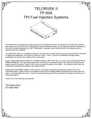
TELORVEK EFI<br />
4.6 Sequential Fuel Injection<br />
System (FT-92)<br />
Page #1<br />
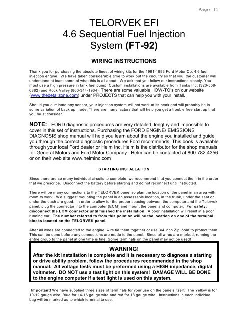
WIRING INSTRUCTIONS<br />
Thank you for purchasing the absolute finest of wiring kits for the 1991-1993 Ford Motor Co. 4.6 fuel<br />
injection engine. W e have taken considerable time to work out the circuitry so that you, the customer will<br />
understand at least some of what this is all about. We ask that you follow our <strong>instructions</strong> closely. You<br />
must use a high pressure in tank fuel pump. Custom <strong>installation</strong>s are available from Tanks Inc. (320-558-<br />
6882) and Rock Valley (800-344-1934). There are some valuable HOW-TO’s on our website<br />
(www.thedetailzone.com) under PROJECTS that can help you with your install.<br />
Should you eliminate any sensor, your injection system will not work at its peak and will probably be in<br />
some variation of back up mode. There are many factors that will help you get a trouble free start up that<br />
you must consider.<br />
NOTE: FORD diagnostic procedures are very detailed, lengthy and impossible to<br />
cover in this set of <strong>instructions</strong>. Purchasing the FORD ENGINE/ EMISSIONS<br />
DIAGNOSIS shop manual will help you learn about the engine you installed and guide<br />
you through the correct diagnostic procedures Ford recommends. This book is available<br />
through your local Ford dealer or Helm Inc. Helm is the distributor for the shop manuals<br />
for General Motors and Ford Motor Company. Helm can be contacted at 800-782-4356<br />
or on their web site www.helminc.com<br />
STARTING INSTALLATION<br />
Since there are so many individual circuits to complete, we recommend that you connect them in the order<br />
that we prescribe. Disconnect the battery before starting and do not reconnect until instructed.<br />
There will be many connections to the TELORVEK panel so plan the location of the panel in an area with<br />
room to work. We suggest mounting the panel in an assessable location, in the trunk, under the seat or<br />
under the dash are good. In order to allow for the proper spacing between the computer and the Telorvek<br />
panel, plug the connector into the computer (ECM) and mount the panel and computer. For safety,<br />
disconnect the ECM connector until finished the <strong>installation</strong>. A poor <strong>installation</strong> will result in a poor<br />
running car. The number referred to from this point on will be the location on one of the terminal<br />
blocks located on the TELORVEK panel.<br />
After all wires are connected to the engine, wire tie them together or use 3/4 inch Zip loom to protect them.<br />
This can be done before any connections are made to the panel. Since all wires are marked, running the<br />
entire group to the panel at one time is fine. Some terminals on the panel may not be used!<br />
WARNING!<br />
After the kit <strong>installation</strong> is complete and it is necessary to diagnose a starting<br />
or drive ability problem, follow the procedures recommended in the shop<br />
manual. All voltage tests must be preformed using a HIGH impedance, digital<br />
voltmeter. DO NOT use a test light on this system! DAMAGE WILL BE DONE<br />
to the engine computer if a test light is used on this system.<br />
Important! W e have supplied three sizes of terminals for your use on the panels itself. The Yellow is for<br />
10-12 gauge wire, Blue for 14-16 gauge wire and red for 18 gauge wire. Instructions in each individual<br />
bag will be marked as to which terminal to use.
Page #2<br />
NOTE <br />
You will be moving around to different terminals on the TELORVEK panel to<br />
make connections. For this reason extra care is needed when making all<br />
connections to the panel.<br />
Bag #60. INJECTORS: The injector wiring is made up in two harnesses, one for the left bank of injectors<br />
and one for the right bank. Locate the right injector connector with the Red and Tan wires and connect it to<br />
cylinder number (1) injector one. Now plug in the rest of the injector connectors (injectors 2, 3, 4) in that<br />
half of the harness. In the left injector harness locate the injector connector with the Red and Black wires<br />
and connect it to injector number (5). Plug in the rest of the injector connectors (injectors 6, 7, 8) and run<br />
all the wires from both haves of the harness to the Telorvek Panel. Using the blue terminals connect the<br />
Red wires (INJ 1->1) and (INJ 5->1) to #1. Now connect the remaining eight wires as follows using the red<br />
terminals, Tan (INJ 1->23) to #23, White (INJ 2->24) to #24, Brown (INJ 3->25) to #25, Lt Blue (INJ 4->26)<br />
to #26, Black (INJ 5->27) to #27, Lt Green (INJ 6->28) to #28, Dk Blue (INJ 7->29) to #29 and Dk Green<br />
(INJ 8->30) to #30.<br />
Bag #61. IGNITION COIL: The 4.6 engine has two coil packs, one for the left spark plugs and one for the<br />
right spark plugs. The coil packs are mounted to each head in front of the engine. The left coil pack<br />
connector has Red, Tan and Lt Blue wires and the right coil pack connector has Red, White and Orange<br />
wires. After attaching the connectors to the coils run the wires back to the Telorvek panel. Connect the<br />
Red wire (LF IGN COIL->6) and (RT IGN COIL->6) using the blue terminals to #6. Using the red terminals<br />
connect the Tan (LF IGN COIL->8) to #8, Lt Blue (LF IGN COIL->9) to #9, White (RT IGN COIL->10) to<br />
#10 and the Orange wire (RT IGN COIL->11) to #11.<br />
Bag #62. IGNITION CONTROL MODULE CONNECTION: The ICM requires some of the wires to be<br />
shielded from any electrical interference, that is why six of the wires (Pink, Gray, Purple, Dk Blue, Dk<br />
Green, Solid Strand) in the connector are wrapped.<br />
Carefully uncoil the harness and plug it into the ICM then run all the wires to the Telorvek panel. Remove<br />
the tape and shielding material back only as far as it is necessary for the length of the wire to be cut and<br />
allowing enough wire to make the connections on the panel. In the shielded harness there is a solid strand<br />
wire with no insulation, install a blue terminal on it and connect it to #22. After the connection is made<br />
wrap the exposed wire from the shielded harness to #22 with electrical tape. Using red terminals the other<br />
five wires in the shielded harness are connected as follows, Pink (ICM 3->12) to #12, Gray (ICM 1->13) to<br />
#13, Purple (ICM 7->14) to #14, Dk Blue (ICM 5->15) to #15 and the Dk Green (ICM 4->16) to #16.<br />
Connect the seven remaining wires running from the ICM connector as follows: Red (ICM 6->4) to #4,<br />
Yellow (ICM 2->7) to #7, Tan (ICM 11->8) to #8, Lt Blue (ICM 12->9) to #9, White (ICM 8->10) to #10,<br />
Orange (ICM 9->11) to #11 and Black (ICM 10->19) to #19.<br />
If desired a tach can be wired into the system by connecting the Yellow wire (7->TACH) to #7<br />
on the panel and run it to the tach.<br />
WARNING !!!<br />
The distributorless ignition system (DIS) on this engine is a high energy<br />
system operating in a dangerous voltage range which could prove to be fatal if<br />
exposed terminals or live parts are contacted. Use extreme caution when<br />
working on the vehicle with the ignition on or the engine running.
Bag #63 CRANK POSITION SENSOR (CPS) : requires the wires to be shielded from any electrical<br />
interference.<br />
Page #3<br />
Carefully uncoil the harness and plug it into the CPS located on the right front of the engine. Run the<br />
wires to the Telorvek panel. Remove the tape and shielding material back only as far as it is necessary for<br />
the length of the wire to be cut and allowing enough wire to make the connections on the panel. In the<br />
shielded harness there is a solid strand wire with no insulation, install a blue terminal on it and connect it<br />
to #22. After the connection is made wrap the exposed wire from the shielded harness to #22 with<br />
electrical tape. Connect the remaining two wires as follows: Dk Blue (CPS->15) to #15 and the Dk Green<br />
wire (CPS->16 to #16.<br />
Bag #64. MASS AIR FLOW SENSOR: Attach the connector to the M.A.F sensor located in the air intake<br />
tube between the intake manifold and air cleaner. Using a blue terminal, connect the Red wire (MAF->4)<br />
to #4. Now using the red terminals, connect the Black (MAF->21) to #21, Tan (MAF->18) to #18 and the<br />
Lt Blue (MAF->17) to #17.<br />
Bag #65. CYLINDER ID SENSOR: requires the wires to be shielded from any electrical interference.<br />
Carefully uncoil the harness and plug it into the sensor located on the left front of the engine. Run the<br />
wires to the Telorvek panel. Remove the tape and shielding material back only as far as it is necessary for<br />
the length of the wire to be cut and allowing enough wire to make the connections on the panel. In the<br />
shielded harness there is a solid strand wire with no insulation, install a blue terminal on it and connect it<br />
to #19. After the connection is made wrap the exposed wire from the shielded harness to #19 with<br />
electrical tape. Connect the remaining two wires as follows: Dk Blue (CYL ID->40) to #40 and the Gray<br />
(CYL ID->57) to #57.<br />
Bag #66.ENGINE COOLANT TEMPERATURE SENSOR (ECT): After attaching the plug to the sensor<br />
located on the lower front of the engine, near the alternator run the two wires to the panel. Connect them<br />
using the red terminals, Lt Green wire (ECT->35) to #35 and the Gray wire (ECT->56) to #56.<br />
Bag #67. THROTTLE POSITION SENSOR (TPS): Plug into the sensor located in the rear of the engine<br />
on the throttle body and run the wires back to the panel. Using the red terminals, connect the Brown (TPS-<br />
>37) to #37, White (TPS->36) to #36 and Gray (TPS->56) to #56.<br />
Bag #68. EXHAUST GAS RECIRCULATION VALVE POSITION SENSOR & EGR SOLENOID: Plug in<br />
the connector to the EGRVP located on the rear of the engine. Using red terminals, connect the Lt Green<br />
wire (EGRVP->38) to #38, Brown wire (EGRVP->37) to #37 and the Gray (EGRVP->57) to #57.<br />
Plug the connector into the EGR solenoid located on the rear of the engine. Using a the red terminals<br />
connect the Red wire (EGR SOL->2) to #2 and the Brown wire (EGR SOL->39) to #39.<br />
Bag #69. INTAKE AIR TEMPERATURE SENSOR (IAT): Plug the connector onto the IAT sensor located<br />
in the air intake tube. Run the wires to the Telorvek Panel and using the red terminals connect the Yellow<br />
wire (IAT->41) to #41 and the Gray wire (IAT->58) to #58.<br />
Bag #70. FUEL PUMP RELAY & INERTIA SWITCH: The EEC module controls the fuel pump relay.<br />
Turning the ignition switch to the run position and not starting the engine, the EEC will cycle the pump for<br />
2-4 seconds. Once the engine starts to crank, the EEC will then turn the pump on. NOTE: You must install<br />
a fuel pump relay into the housing or the pump will not operate. Use the Ford part<br />
#E3FZ-9345-B fuel pump relay.<br />
Mount the relay near the Telorvek panel. Connect the Red wire (FP RELAY->31) to #31, Light Blue (FP<br />
RELAY->48) to #48, Tan (FP RELAY->33) to #33 and the Yellow (FP RELAY->32) to #32.
Page #4<br />
INERTIA SWITCH: The inertia switch is designed to disconnect the ignition voltage from the fuel pump in<br />
the event of a accident. This obviously kills the engine to prevent fire.<br />
Mount the inertia switch in the trunk and run the wires to the Telorvek panel. Connect the Tan wire<br />
(INERTIA->33) to #33 and the other Tan wire (INERTIA SW->FP) to the positive terminal on the fuel<br />
pump. A wire must be connected to the negative terminal on the pump and run to a good ground. Use<br />
Ford inertia switch part #F2AZ-9341-A.<br />
Bag #71. OXYGEN SENSOR (2): This area of the vehicle is hot so keep the wires away from the<br />
exhaust. Two sensors are required per engine. NOTE: If you are using headers, mount the O2 sensors in<br />
the collectors. Plug in the connectors into the O2 sensors following the wording printed on the wires and<br />
run the wires to the Telorvek panel. Using the blue terminals connect the Orange wires (LEFT O2->5) and<br />
(RIGHT O2->5) to #5, Black Wires (LEFT O2->20) and (RIGHT O2->20 to #20. Using the red terminals<br />
connect the Gray wires (LEFT O2->59) and (RIGHT O2->59) to #59. Connect the Dark Blue (LEFT O2-<br />
>42) to #42 and the Light Blue (RIGHT O2->43) to #43.<br />
Bag #72. IDLE SPEED CONTROL: The ISC is located on the rear of the engine in the throttle body. Plug<br />
in the connector and run the wires back to the panel. Using the red terminals, connect the White wire<br />
(ISC->51) to #51 and the Red wire (IAC->3) to #3.<br />
Bag #73. DATA LINK CONNECTOR: Mount the connector inside the vehicle under the dash and run the<br />
wires to the Telorvek Panel. Using the red terminals connect the Tan (VIP 1->47) to #47, Gray (VIP 1-<br />
>58) to #58, Pink (VIP 1->46) to #46, Light Green (VIP 1->49) to #49, Light Blue (VIP 1->48) to #48 and<br />
the White (VIP 2->50) to #50.<br />
The remaining two wires are for the service engine soon (SES) light. You must use a wire un-grounded<br />
light.<br />
S.E.S LT: Connect the Lt Green wire (49->SES LT) to #49 on the Telorvek Panel and run it to a dash<br />
indicator light and connect it to one of the wires running from the light. The Red wire (3->SES LT)<br />
connects to #3 on the panel and run to the other wire running from the light. This light is not required as<br />
the yellow light on top of the Telorvek Panel has the same function.<br />
Bag #74 OCTANE ADJUST: The ECM measures voltage across the octane adjust connector and uses<br />
this information to modify ignition spark advance. Leave this connector plugged together but if you<br />
experience detonation while driving, un-plug this connector or use higher octane gasoline. Using the red<br />
terminals connect the Gray (OCTA ADJ->60) to #60 and the Dk Green (OCTA ADJ->52) to #52.<br />
Bag #75. VEHICLE SPEED SENSOR: Install the connector onto the speed sensor located in the<br />
speedometer assembly on the transmission and run the wires back to the Telorvek panel. Using the red<br />
terminals, connect the Black wire (VEH SPD SEN->21) to #21 and the Dark Green wire (VEH SPD SEN-<br />
>45) to #45.<br />
Bag #76. CANISTER PURGE SOLENOID: Plug the connector into the Canister Purge Solenoid. Using<br />
the using red terminals, connect the Red wire (CAN PURGE->2) to #2 and the Gray wire (CAN PURGE-<br />
>44) to #44.
Page #5<br />
Bag #77. PARK/NEUTRAL RELAY: This system was developed to allow a regular park / neutral switch to<br />
tell the computer when the vehicle is in park, neutral or drive. Since the signals are different, we have<br />
made this small circuit that will connect to a stock Ford neutral switch or splice to just about any two wire<br />
neutral switch. The signal input controls the idle air control (IAC), vehicle speed sensor diagnostics (VSS)<br />
and exhaust gas recirculation (EGR).<br />
The regular car wiring that normally runs to the neutral safety now connects to the P/N relay kit. If you are<br />
installing this relay into a vehicle that has a <strong>Ron</strong> <strong>Francis</strong> Wire Works wiring kit, in that kit wires were<br />
supplied to be connected to a neutral safety switch. These wires will plug directly into the 12 gauge purple<br />
and blue wires running from the relay and will be a color for color match. Now connect the 18 gauge blue<br />
wire running from the relay to the white/pink wire running from the neutral safety switch. Connect the<br />
black wire to the red/blue wire running from the neutral safety switch and connect it to a good ground.<br />
Connect the White wire to #53 on the Telorvek Panel.<br />
NOTE: Using any other standard neutral switch requires only removing the plug and splicing. If the<br />
connector on the wires doesn't fit your application then remove it and connect the wires to the switch.<br />
<br />
<br />
<br />
<br />
The 12 gauge blue wire in the plug must be connected to the 12 volt supply from the ignition<br />
switch. This wire becomes hot (12 Volts) when you turn the key to crank.<br />
The 12 gauge purple wire is connected to the wire that runs to the starter solenoid.<br />
The 18 gauge blue wire connects to one of the terminals on the neutral safety switch.<br />
The 18 gauge black wire connects to the other terminal on the neutral safety switch and run to<br />
a good ground.<br />
Run the White wire to #53 on the panel. The relay used in this kit is a GM (part #14100455).<br />
FINISHING UP<br />
Connect the large pre-wired orange wire to the ignition circuit of your ignition switch. This is an ignition<br />
feed that is controlled by the ignition switch. This is not an accessory feed and must remain hot even<br />
when the engine is cranking.<br />
Connect the large pre-wired red battery feed wire to a battery feed. This is a battery feed that must remain<br />
hot even with the key off. Make sure this is a good connection. If you have a Master Disconnect switch,<br />
install this wire on the battery side of the switch so it will remain hot with the Disconnect off.<br />
The black ground wire from the TELORVEK Panel runs direct to the battery. Run the battery ground<br />
directly to the engine not the frame first. This includes rear mounted batteries.<br />
STARTING THE ENGINE<br />
You have now made all of the connections necessary to TRY to start your car. If you try now, you will be<br />
disappointed since you did not hook up the battery. You can do so now.<br />
Priming the Fuel System<br />
The fuel system can be primed by removing the Tan wire (INERTIA->33) from terminal #33 and applying<br />
12 volts to this wire. After the fuel system is primed, be sure to re-install the Tan wire back onto terminal<br />
#33.<br />
CARE SHOULD BE TAKEN TO AVOID ANY SPILLAGE OR INJURY WHILE<br />
FOLLOWING THIS PROCEDURE.
Page #6<br />
We're trying...<br />
The Detail Zone has made every effort to assure a quality <strong>product</strong> and can assure you that this system<br />
works well in your application. Most of the 'problem' calls we have had to date are basic trouble shooting<br />
questions which have nothing to do with the TELORVEK system we sold you.<br />
We are committed to offering the most user friendly wiring systems available and support this with many<br />
years experience in the wiring and fuel injection fields. Please be certain that all connections are correct<br />
and tests run before calling. Your unit can be tested at any Ford Dealership with no difficulty.<br />
USING THE CHECK ENGINE LIGHT<br />
The check engine light performs just the same as it would in any newer car, when the key is turned on<br />
(engine not running) the light will stay on until the engine starts.<br />
W hen the check engine light comes on during engine operation, it is an indication of a fault in the system.<br />
It will be necessary to have the computer perform a self test diagnostic procedure. The self test is divided<br />
into three specialized tests:<br />
KEY ON ENGINE OFF SELF TEST (KOEO): For this test the fault must be present at the time of testing.<br />
For intermittent , refer to continuous memory codes.<br />
ENGINE RUNNING ("R") SELF TEST: The sensors are checked under operating conditions and at<br />
normal operating temperatures.<br />
CONTINUOUS ("C") MEMORY CODES: These codes are issued as a result of information stored while<br />
the vehicle was in normal operation.<br />
READING THE CHECK ENGINE LIGHT: A service code is reported by a flash of the check engine light.<br />
All service codes are three digit numbers, such as 112. The light will display one flash, then, after a two<br />
second pause, the light will flash twelve times. All self test codes (if any) will be displayed and then a<br />
delay of six seconds, a single half second separator flash and another six second delay and then the<br />
continuous memory codes will be flashed.<br />
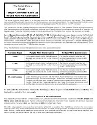
If the light remains on after the<br />
engine is running then follow the<br />
procedures below to have the check<br />
engine light flash trouble<br />
codes.Locate the V.I.P connector &<br />
connect a jumper wire between the<br />
terminals shown in the drawing.<br />
Trouble Code Chart<br />
Listed below is a trouble code chart that pertains to all models of Ford vehicles. Some of the codes listed<br />
below DO NOT pertain to your application.<br />
ECM<br />
CODE<br />
CONDITIONS<br />
KEY:<br />
O= Key On Engine Off<br />
R= Engine Running<br />
C= Continuous Memory<br />
Definition<br />
111 O R C System Pass<br />
112 O C Intake Air Temp sensor circuit below minimum voltage<br />
113 O C Intake Air Temp sensor circuit above maximum voltage<br />
114 O R Intake Air Temp higher or lower than expected<br />
116 O R Engine Coolant temp higher or lower than expected<br />
117 O C Engine Coolant temp sensor circuit below minimum voltage
Page #7<br />
ECM<br />
CODE<br />
CONDITIONS<br />
KEY:<br />
O= Key On Engine Off<br />
R= Engine Running<br />
C= Continuous Memory<br />
Definition<br />
118 O C Engine Coolant temp sensor circuit above maximum voltage<br />
121 O R C Closed throttle voltage higher or lower than expected<br />
Indicates throttle position voltage inconsistent with the MAF<br />
sensor<br />
122 O C Throttle position sensor circuit below minimum voltage<br />
123 O C Throttle position sensor circuit above maximum voltage<br />
124 C Throttle position sensor voltage higher than expected<br />
125 C Throttle position sensor voltage lower than expected<br />
126 O R C MAP / BARO sensor higher or lower than expected<br />
128 R MAP sensor vacuum hose damaged or disconnected<br />
129 R Insufficient MAP / Mass Air Flow change during dynamic<br />
response test<br />
136 R Lack of heated oxygen sensor switch during KOER, indicates lean<br />
(Bank #2)<br />
137 R Lack of heated oxygen sensor switch during KOER, indicates rich<br />
(Bank #2)<br />
139 C No heated oxygen sensor switches detected (Bank #2)<br />
144 C No heated oxygen sensor switches detected (Bank #1)<br />
157 C Mass Air Flow sensor circuit below minimum voltage<br />
158 O C Mass Air Flow sensor circuit above maximum voltage<br />
159 O R Mass Air Flow higher or lower than expected<br />
167 R Insufficient throttle position change during dynamic response test<br />
171 C Fuel system at adaptive limits, heated O2 sensor unable to switch<br />
(Bank #1)<br />
172 R C Lack of heated O2 switches, indicates lean (Bank #1)<br />
173 R C Lack of heated O2 switches, indicates rich (Bank #1)<br />
175 C Fuel system at adaptive limits, heated O2 sensor unable to switch<br />
(Bank #2)<br />
176 C Lack of heated O2 switches, indicates lean (Bank #2)<br />
177 C Lack of heated O2 switches, indicates rich (Bank #2)<br />
179 C Fuel system at lean adaptive limit at part throttle, system rich<br />
(Bank #1)<br />
181 C Fuel system at lean adaptive limit at part throttle, system lean<br />
(Bank #1)<br />
184 C Mass Air Flow higher than expected
Page #8<br />
ECM<br />
CODE<br />
CONDITIONS<br />
KEY:<br />
O= Key On Engine Off<br />
R= Engine Running<br />
C= Continuous Memory<br />
Definition<br />
185 C Mass Air Flow lower than expected<br />
186 C Injector pulsewidth higher than expected<br />
187 C Injector pulsewidth lower than expected<br />
188 C Fuel system at lean adaptive limit at part throttle, system rich<br />
(Bank #2)<br />
189 C Fuel system at rich adaptive limit at part throttle, system lean<br />
(Bank #2)<br />
193 C Flexible fuel sensor circuit failure<br />
211 C Profile ignition pick up circuit failure<br />
212 C Loss off ignition diagnostic monitor input to PCM/Spout circuit<br />
grounded<br />
213 R Spout circuit open<br />
214 C Cylinder identification circuit failure<br />
215 C PCM detected coil #1 primary circuit failure<br />
216 C PCM detected coil #2 primary circuit failure<br />
217 C PCM detected coil #3 primary circuit failure<br />
218 C Loss of ignition diagnostic monitor signal left side<br />
219 C Spark timing defaulted to 10 degrees - Spout circuit open<br />
221 C Spark timing error<br />
222 C Loss of ignition diagnostic monitor signal right side<br />
223 C Loss of dual plug inhibit control<br />
224 C PCM detected coil 1,2,3 or 4 primary circuit failure<br />
225 R Knock not sensed during dynamic response test<br />
226 O Ignition diagnostic module signal not received<br />
232 C PCM detected coil 1,2,3 or 4 primary circuit failure<br />
238 C PCM detected coil 4 primary circuit failure<br />
241 C ICM to PCM pulse width transmission error<br />
244 C CID circuit fault present when cylinder balance test requested<br />
311 R Air system inoperative (Bank #1)<br />
312 R Air system misdirected<br />
313 R Air system not bypassed<br />
314 R Air system inoperative (Bank #2)<br />
326 R C EGR circuit voltage lower than expected
Page #9<br />
ECM<br />
CODE<br />
CONDITIONS<br />
KEY:<br />
O= Key On Engine Off<br />
R= Engine Running<br />
C= Continuous Memory<br />
Definition<br />
327 O R C EGR circuit below minimum voltage<br />
328 O R C EGR closed valve voltage lower than expected<br />
332 R C Insufficient EGR flow detected<br />
334 O R C EGR closed valve voltage higher than expected<br />
335 O EGR sensor voltage higher or lower than expected<br />
336 R C Exhaust pressure high / EGR circuit voltage higher than expected<br />
337 O R C EGR circuit above maximum voltage<br />
338 C Engine coolant temperature lower than expected (thermostat test)<br />
339 C Engine coolant temperature higher than expected (thermostat test)<br />
341 O Octane adjust service pin open<br />
411 R Cannot control RPM during KOER low RPM check<br />
412 R Cannot control RPM during KOER high RPM check<br />
415 O R Idle air control system at maximum adaptive lower limit<br />
416 O R Idle air control system at upper adaptive learning limit<br />
452 C Insufficient input from vehicle speed sensor<br />
511 O PCM read only memory test failure<br />
512 C PCM keep alive memory test failure<br />
513 C PCM internal voltage failure<br />
519 O Power steering pressure switch circuit open<br />
521 C Power steering pressure switch circuit did not change states<br />
during KOER<br />
522 O Vehicle not in park or neutral during KOEO test<br />
524 O C Low speed fuel pump circuit open (battery to PCM)<br />
525 O Vehicle was either in gear or A/C was on during self test<br />
527 O Park / neutral position switch circuit open or A/C on during self<br />
test<br />
529 C Data communication link or PCM circuit failure<br />
532 C Cluster control assembly circuit failure<br />
533 C Data communication link or electronic instrument cluster circuit<br />
failure<br />
536 R C Brake on / off circuit failure / not actuated during KOER test
Page #10<br />
ECM<br />
CODE<br />
CONDITIONS<br />
KEY:<br />
O= Key On Engine Off<br />
R= Engine Running<br />
C= Continuous Memory<br />
Definition<br />
538 R Insufficient RPM change during KOER dynamic response test<br />
539 O A/C on during self test<br />
542 O C Fuel pump secondary circuit failure<br />
543 O C Fuel pump secondary circuit failure<br />
551 O Idle air control circuit failure<br />
552 O Secondary air injection bypass circuit failure<br />
553 O Secondary air injection diverter circuit failure<br />
554 O Fuel pressure regulator control circuit failure<br />
556 O C Fuel pump relay primary circuit failure<br />
557 O C Low speed fuel pump primary circuit failure<br />
558 O EGR vacuum regulator circuit failure<br />
559 O A/C on relay circuit failure<br />
563 O High speed fan control circuit failure<br />
564 O Fan control circuit failure<br />
565 O Canister Purge circuit failure<br />
566 O 3-4 shift solenoid circuit failure<br />
578 O R A/C pressure sensor circuit shorted (VCRM)<br />
579 O R Insufficient A/C pressure change (VCRM)<br />
581 O R Power to fan circuit over current (VCRM)<br />
582 O R Fan circuit open (VCRM)<br />
583 O R Power to fuel pump over current (VCRM)<br />
584 O R Power ground circuit open (pin #1) (VCRM)<br />
585 O R Power to A/C clutch over current (VCRM)<br />
586 O R A/C clutch circuit open (VCRM)<br />
587 O R C Variable control relay module communication failure<br />
617 C 1-2 shift error<br />
618 C 2-3 shift error<br />
619 C 3-4 shift error<br />
621 O Shift solenoid 1 circuit failure<br />
622 O Shift solenoid 2 circuit failure<br />
624 O C Electronic pressure control circuit failure<br />
625 O Electronic pressure control driver open in PCM
Page #11<br />
ECM<br />
CODE<br />
CONDITIONS<br />
KEY:<br />
O= Key On Engine Off<br />
R= Engine Running<br />
C= Continuous Memory<br />
Definition<br />
626 O Coast clutch solenoid circuit failure<br />
627 O C Torque converter clutch solenoid circuit failure<br />
628 O C Excessive converter clutch slippage<br />
629 O Torque converter clutch solenoid circuit failure<br />
631 O Transmission control indicator lamp circuit failure<br />
632 R Transmission control switch circuit did not change states during<br />
KOER test<br />
634 C Manual lever position switch voltage higher or lower than<br />
expected<br />
636 O R Transmission oil temp higher or lower than expected<br />
637 O C Transmission oil temp sensor circuit above maximum voltage (-40<br />
F indicated circuit open)<br />
638 O C Transmission oil temp sensor circuit below minimum voltage (-<br />
290 F indicated circuit shorted)<br />
639 R C Insufficient input from transmission speed sensor<br />
641 O Shift solenoid 3 circuit failure<br />
643 O C Torque converter clutch circuit failure<br />
645 C Incorrect gear ratio obtained for first gear<br />
646 C Incorrect gear ratio obtained for second gear<br />
647 C Incorrect gear ratio obtained for third gear<br />
648 C Incorrect gear ratio obtained for fourth gear<br />
649 C Electronic pressure control higher or lower than expected<br />
651 C Electronic pressure control circuit failure<br />
652 O Torque converter clutch solenoid circuit failure<br />
654 O Manual lever position sensor not indicating park<br />
656 C Torque converter clutch continuous slip error<br />
657 C Transmission over temperature condition occurred<br />
998 C Hard fault present (FMEM mode)
Page #12<br />
Breakout Box Circuit Diagnosis<br />
The Telorvek panel can be used as a BREAKOUT BOX for testing circuits running to and from the EEC<br />
Processor. Listed below is the Ford circuit number, circuit description, E.E.C processor pin number,<br />
Telorvek panel number the circuit runs to, Ford wire color and the color of wire we used. Following the<br />
diagnostic procedures that can be found in the ENGINE / EMISSIONS DIAGNOSIS SHOP MANUAL that<br />
can be purchased at your local Ford dealer all trouble codes can be diagnosed.<br />
Circuit Description EEC pin# Panel # Ford Color TDZ Color<br />
361 Ign, Lf/Rt Injectors 1 Red Red<br />
361 Ign, Can Purge, EGR Sol 2 Red Red<br />
361 Ign, IAC, S.E.S LT 3 Red Red<br />
361 Ign, ICM, MAF 37,57 4 Red Red<br />
361 Ign, LFT O2,RT O2 5 Red Red<br />
361 Ign, Coils 6 Red Red<br />
11 ICM 2 4 7 Tan/Yellow Yellow<br />
97 LF ign coil,ICM 11 8 Tan/Lt Green Tan<br />
98 LF ign coil,ICM 12 9 Tan/Lt Blue Lt Blue<br />
95 RT ign coil, ICM 8 10 Tan/Red White<br />
96 RT ign coil, ICM 9 11 Tan/Orange Orange<br />
929 ICM 3 36 12 Pink Pink<br />
395 ICM 1 56 13 Gray/Orange Gray<br />
259 ICM 7 16 14 Orange/Red Purple<br />
349 ICM 5,CKP Sensor 15 Dk Blue Dk Blue<br />
350 ICM 4,CKP Sensor 16 Gray Dk Green<br />
967 MAF 50 17 Lt Blue/Red Lt Blue<br />
968 MAF 9 18 Tan/LT Blue Tan<br />
570 ICM 10,CID Shield 19 Black/White Black<br />
570 LF & RT O2 40,60 20 Black/White Black<br />
570 MAF,VSS 6,20 21 Black/White Black<br />
48 ICM, CRK POS Shield 22 Black Solid<br />
555 Injector 1 58 23 Tan Tan<br />
556 Injector 2 59 24 White White<br />
557 Injector 3 39 25 Brown/Yellow Brown<br />
558 Injector 4 35 26 Brown/Lt Blue Lt Blue<br />
559 Injector 5 15 27 Tan/Black Black<br />
560 Injector 6 12 28 Lt Green/Orange Lt Green<br />
561 Injector 7 13 29 Tan/Red Dk Blue<br />
562 Injector 8 14 30 Lt Blue Dk Green<br />
361 Ign, F/P Relay 31 Red Red<br />
37 Batt Feed, F/P Relay 1 32 Yellow Yellow<br />
239 F/P Relay, Inertia Sw 8 33 Dk Green/Yellow Tan<br />
73 A/C Cut out Relay 54 34 Orange/Lt Blue ----<br />
354 ECT Sensor 7 35 Lt Green/Red Lt Green<br />
355 TPS 47 36 Gray/White White<br />
351 TPS,EGRVP 26 37 Brown/White Brown<br />
352 EGRVP 27 38 Brown/Lt Green Lt Green<br />
360 EGR 33 39 Brown/Pink Brown<br />
795 CID 24 40 Dk Green Dk Blue<br />
743 IAT 25 41 Lt Green/Pink Yellow<br />
94 LF O2 43 42 Red/Black Dk Blue<br />
74 RT O2 44 43 Gray/Lt Blue Lt Blue<br />
101 Canister Purge 11 44 Gray/Yellow Gray<br />
150 VSS 3 45 Gray/Black Dk Green<br />
915 VIP 1 19 46 Pink/Lt Blue Pink<br />
914 VIP 1 18 47 Tan/Orange Tan<br />
926 VIP 1,FP Relay 22 48 Lt Blue/Orange Lt Blue<br />
201 S.E.S Lt,VIP 1 17 49 Tan/Red Lt Green<br />
209 VIP 2 48 50 White/Pink White<br />
264 IAC 21 51 White/Lt Blue White<br />
240 Octane Adjust 29 52 White/Red Dk Green<br />
33 MLPS 30 53 White/Pink White<br />
737 Check Temp Ind. 53 54 White/Lt Blue White<br />
198 A/C Clutch 10 55 Dk Green/Orange ----<br />
359 ECT,TPS 46 56 Gray/Red Gray<br />
359 EGRVP,CID 57 Gray/Red Gray<br />
359 IAT,VIP 1 58 Gray/Red Gray<br />
359 LF,RT O2 59 Gray/Red Gray<br />
359 Octane Adjust 30 Gray/Red Gray
Page #13<br />
Fuse Designation & Size<br />
The harness has a total of eight fuses. Shown below is a diagram of what each fuse protects. The<br />
illustration is the front view of the Telorvek panel.<br />
Fuse Block #1 Fuse Block #2<br />
Fuse<br />
Designation<br />
Fuse Size<br />
Block #1<br />
Fuse<br />
Designation<br />
Fuse Size<br />
Block #2<br />
Left & Right Injectors 15 AMP Left & Right O2 Sensors 20 AMP<br />
Canister Purge & EGR Solenoids 10 AMP Ignition Coil Wires 20 AMP<br />
IAC, Service Engine Soon LT 10 AMP Fuel Pump Relay 10 AMP<br />
Ignition Control Module, Mass Air<br />
Flow Sensor, Electronic Engine<br />
Control Module<br />
15 AMP Fuel Pump Relay, Electronic Engine<br />
Control Module<br />
20 AMP<br />
Copyright Infringement<br />
The Detail Zone has taken the extra effort to produce a quality, easy to<br />
understand <strong>instructions</strong>. We will aggressively prosecute any other harness<br />
supplier who attempts to copy this material!!<br />
COPYRIGHT<br />
©1994 The Detail Zone