Nonlinear dynamic behavior of structural frames constructed with 3D ...
Nonlinear dynamic behavior of structural frames constructed with 3D ...
Nonlinear dynamic behavior of structural frames constructed with 3D ...

You also want an ePaper? Increase the reach of your titles
YUMPU automatically turns print PDFs into web optimized ePapers that Google loves.
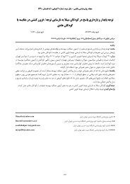
1 St international conference on seismic retr<strong>of</strong>itting, Tabriz-Iran, 20-22 October 2008<br />
<strong>Nonlinear</strong> <strong>dynamic</strong> <strong>behavior</strong> <strong>of</strong> <strong>structural</strong> <strong>frames</strong> <strong>constructed</strong> <strong>with</strong><br />
<strong>3D</strong> wall panels <strong>with</strong> Vertical Irregular arrangement<br />
Omid Rezaifar 1 , Majid Gholhaki 2<br />
1,2- Assistant Pr<strong>of</strong>essor, Faculty <strong>of</strong> Civil Engineering, Semnan University, Semnan, Iran<br />
rezayfar@yahoo.com<br />
mgholhaki@semnan.ac.ir<br />
ABSTRACT<br />
The current study investigates the hysteresis <strong>behavior</strong> for combined systems, RC frame, and pre-cast <strong>3D</strong> wall<br />
sandwich panels, in non-linear material properties. The seismic <strong>behavior</strong> <strong>of</strong> building <strong>constructed</strong> by <strong>3D</strong> wall<br />
panels is studied for absorb <strong>of</strong> energy and dissipation <strong>of</strong> it <strong>with</strong> material nonlinearities. The results are compared<br />
regular bending RC <strong>frames</strong> to complete box type shotcrete sandwich panels system and present the differences <strong>of</strong><br />
hysteresis <strong>behavior</strong> for each system and any <strong>of</strong> cases <strong>with</strong> irregularity in vertical stiffness such as s<strong>of</strong>t story. In<br />
this study, material nonlinearity simulated <strong>with</strong> Drucker-Prager failure criteria. Behavior <strong>of</strong> FEM model verified<br />
<strong>with</strong> experimental result. Seventy-three <strong>frames</strong> analyzed and result were investigated and compared. Compare <strong>of</strong><br />
energy dissipation for stories and influence <strong>of</strong> s<strong>of</strong>t story are presented.<br />
Keywords: panel structures, <strong>dynamic</strong> <strong>behavior</strong>, nonlinear analysis.<br />
1. INTRODUCTION<br />
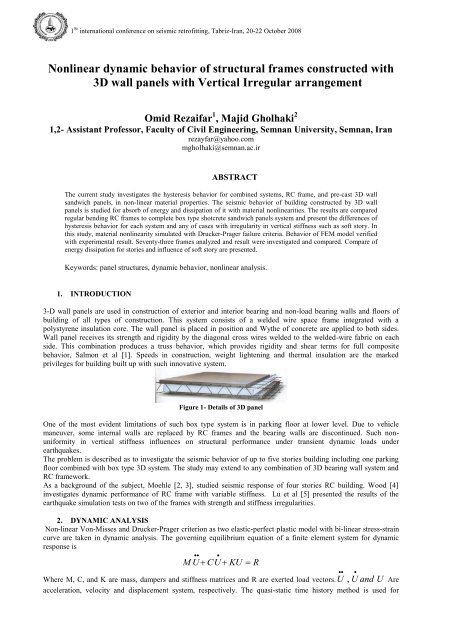
3-D wall panels are used in construction <strong>of</strong> exterior and interior bearing and non-load bearing walls and floors <strong>of</strong><br />
building <strong>of</strong> all types <strong>of</strong> construction. This system consists <strong>of</strong> a welded wire space frame integrated <strong>with</strong> a<br />
polystyrene insulation core. The wall panel is placed in position and Wythe <strong>of</strong> concrete are applied to both sides.<br />
Wall panel receives its strength and rigidity by the diagonal cross wires welded to the welded-wire fabric on each<br />
side. This combination produces a truss <strong>behavior</strong>, which provides rigidity and shear terms for full composite<br />
<strong>behavior</strong>, Salmon et al [1]. Speeds in construction, weight lightening and thermal insulation are the marked<br />
privileges for building built up <strong>with</strong> such innovative system.<br />
Figure 1- Details <strong>of</strong> <strong>3D</strong> panel<br />
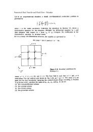
One <strong>of</strong> the most evident limitations <strong>of</strong> such box type system is in parking floor at lower level. Due to vehicle<br />
maneuver, some internal walls are replaced by RC <strong>frames</strong> and the bearing walls are discontinued. Such nonuniformity<br />
in vertical stiffness influences on <strong>structural</strong> performance under transient <strong>dynamic</strong> loads under<br />
earthquakes.<br />
The problem is described as to investigate the seismic <strong>behavior</strong> <strong>of</strong> up to five stories building including one parking<br />
floor combined <strong>with</strong> box type <strong>3D</strong> system. The study may extend to any combination <strong>of</strong> <strong>3D</strong> bearing wall system and<br />
RC framework.<br />
As a background <strong>of</strong> the subject, Moehle [2, 3], studied seismic response <strong>of</strong> four stories RC building. Wood [4]<br />
investigates <strong>dynamic</strong> performance <strong>of</strong> RC frame <strong>with</strong> variable stiffness. Lu et al [5] presented the results <strong>of</strong> the<br />
earthquake simulation tests on two <strong>of</strong> the <strong>frames</strong> <strong>with</strong> strength and stiffness irregularities.<br />
2. DYNAMIC ANALYSIS<br />
Non-linear Von-Misses and Drucker-Prager criterion as two elastic-perfect plastic model <strong>with</strong> bi-linear stress-strain<br />
curve are taken in <strong>dynamic</strong> analysis. The governing equilibrium equation <strong>of</strong> a finite element system for <strong>dynamic</strong><br />
response is<br />
<br />
<br />
M U<br />
CU<br />
KU R<br />
Where M, C, and K are mass, dampers and stiffness matrices and R are exerted load vectors. U<br />
<br />
, U <br />
and U Are<br />
acceleration, velocity and displacement system, respectively. The quasi-static time history method is used for<br />
1
Acc. cm/s 2<br />
1 St international conference on seismic retr<strong>of</strong>itting, Tabriz-Iran, 20-22 October 2008<br />
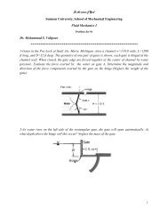
analysis. Ground acceleration record as it shown is adopted, figure 2. The duration <strong>of</strong> record is totally 21 seconds<br />
<strong>with</strong> the maximum amplitude <strong>of</strong> 700.8 Gall. The major exerted energy is occurred at the first 10 second.<br />
800<br />
600<br />
400<br />
200<br />
0<br />
-200<br />
5 10 15 20 25<br />
-400<br />
-600<br />
-800<br />
Figure 2- used ground acceleration record<br />
Both linear and non-linear material models are considered in current study. The analysis is performed in ANSYS<br />
environment and two non-linear elements, shell 91 and solid 65 are adopted for concrete at system and component<br />
level, respectively. The orthogonal wire meshes are modeled by beam 23.<br />
Material properties <strong>of</strong> shotcrete and wire meshes are tabulated in table 1. All details are those experimentally<br />
measured, [6].<br />
Table 1- Material properties used in analysis(stresses in kg/cm 2 )<br />
Material Poisson<br />
ratio<br />
Specific<br />
Gravity T/m 3<br />
Young<br />
Modulus<br />
Yield stress Tensile<br />
strength<br />
Compression<br />
strength<br />
Steel bars 0.28 7.855 2.06e6 4700 - -<br />
Concrete 0.2 2.4 2.4e5 - 30 300<br />
Shotcrete 0.15 2.2 1.5e5 - 28 180<br />
In addition, the stress-strain curves for welded wire meshes are obtained through tensile test. It was based on ASTM.<br />
The final diameter <strong>of</strong> wires after cold drawing manufacturing is 3.5 mm. There is one stage annealing work have to<br />
be done to release the residual stresses.<br />
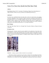
3. VERIFYING MODELING WITH EXPERIMENT RESULT<br />
Fem model <strong>of</strong> one panel is analyzed <strong>with</strong> drucker-prager criteria. This panel was <strong>constructed</strong> and tested versus shear<br />
loading. Panel in various dimensions tested. Setup <strong>of</strong> panel test can be seen in figure 3.<br />
Figure 3- setup <strong>of</strong> panel test<br />
Result <strong>of</strong> experiment obtained. FEM model result and test result compared. It can be seen that result <strong>of</strong> FEM<br />
modeling is compatible and verified. Accuracy <strong>of</strong> modeling in nonlinear material <strong>with</strong> drucker-prager for concrete<br />
compared <strong>with</strong> experimental.<br />
4. SENSITIVITY ANALYSIS<br />
To reduce the executive time <strong>of</strong> analysis, using <strong>of</strong> panel symmetry in thickness, only one-half <strong>of</strong> the <strong>3D</strong> panel is<br />
modeled for shear loading. the analysis <strong>of</strong> full panel and one-half thickness have same shear and bending <strong>behavior</strong>.<br />
In <strong>dynamic</strong> analysis, especially when material <strong>behavior</strong> is considered as non-linear, the time step sizing in the<br />
analysis becomes important to get results that are more accurate. Therefore, it should be chosen infinitesimal. In The<br />
2
1 St international conference on seismic retr<strong>of</strong>itting, Tabriz-Iran, 20-22 October 2008<br />
present study, t is taken as identical for all cases and equal 0.005 sec.. Table 2 shows the sensitivity analysis to<br />
obtain minimum it for all models.<br />
Table 2 - Sensitivity <strong>of</strong> Base absorbed shear to the time interval it<br />
t (sec.) 0.02 0.01 0.005 0.002 0.001<br />
Base absorbed shear (Ton) 1019 753 530 522 520<br />
In order to evaluate <strong>dynamic</strong>al characterizing e.g. periods and mode shapes <strong>of</strong> all <strong>frames</strong>, the Modal analysis is<br />
conducted. As example for the model <strong>with</strong> four stories and three spans, that has 12 meters height. The period<br />
obtained from linear analysis is 0.509 sec.. The theoretical period is equal to 0.451 sec from equation 1.<br />
3<br />
4<br />
(1) T H<br />
For concrete <strong>frames</strong> is equal to 0.07, that shows low percentage <strong>of</strong> error and adequate precision for modeling.<br />
F2S1<br />
Table 3- figure <strong>of</strong> models<br />
F*S*001 F*S*002 F*S*003 F*S*004 F*S*005 F*S*006 F*S*007<br />
F2S2<br />
F5S2<br />
F5S3<br />
F5S4<br />
5. NUMERICAL MODELS<br />
To investigate the changes in building stiffness <strong>constructed</strong> in combination <strong>of</strong> <strong>3D</strong> panels and RC <strong>frames</strong>, the<br />
following figures are eight types <strong>of</strong> <strong>frames</strong> <strong>with</strong> different panel distribution in spans. All beams and column cross<br />
sections are 30 by 30 cm dimensions <strong>with</strong> 2.5% reinforcement density. The <strong>frames</strong> span length is identical for all<br />
models and plan <strong>of</strong> each floor is 400 centimeters. Figures <strong>of</strong> all models are presented in table 3.<br />
Different stiffness in level <strong>of</strong> each system leads to different base shear for each case; furthermore, distribution <strong>of</strong><br />
shear is different because <strong>of</strong> mass distribution. Applying the base acceleration record to all models in both linear and<br />
non-linear analysis, it can estimate the distribution <strong>of</strong> base shear, which could balance the <strong>dynamic</strong>al equilibrium <strong>of</strong><br />
the <strong>structural</strong> system.<br />
To investigate the real <strong>behavior</strong> <strong>of</strong> structure, <strong>dynamic</strong>al analysis on models are performed by incorporate the<br />
material nonlinearity for concrete by drucker-prager criteria.<br />
6. HYSTERESIS BEHAVIOR OF FRAMES UNDER EARTHQUAKE RECORDS<br />
Applying the NAGHAN base acceleration record to all models in both linear and non-linear analysis, one can<br />
estimate the base shear that could balance the <strong>dynamic</strong>al equilibrium <strong>of</strong> the <strong>structural</strong> system. Hysteresis <strong>of</strong> <strong>frames</strong><br />
investigated and compared in this section. Energy dissipation and overall behaves <strong>of</strong> models is obtained. It has only<br />
presented three models and some results <strong>of</strong> it.<br />
Models have some different value <strong>of</strong> frequency. Bare frame frequency is 4.0, s<strong>of</strong>t storey frame 5.84, semi s<strong>of</strong>t storey<br />
30, and full panel is about 40 Hz. Some <strong>of</strong> these frequencies are presented in table 4. It shows that full panel systems<br />
have higher frequency in compare <strong>of</strong> bare <strong>frames</strong> and s<strong>of</strong>t story <strong>frames</strong>. S<strong>of</strong>t storey <strong>frames</strong> have frequency higher<br />
than bare frame and little than full panel systems. S<strong>of</strong>t storey frequency is more similar to bare frame. It is because<br />
<strong>of</strong> low stiffness <strong>of</strong> concrete columns in first story. The value <strong>of</strong> frequency is increased by increasing height <strong>of</strong><br />
system generally. F2S1001, bare frame absorbed 73.725 kN base shear. It deformed 33.51 mm at upper point <strong>of</strong><br />
frame. It shows that hysteresis curve <strong>of</strong> frame is fat. Energy Dissipation <strong>of</strong> frame is higher than other models, and is<br />
same <strong>of</strong> bare frame models in theoretically. The complete list <strong>of</strong> top displacement and base shear is presented in<br />
table 5.<br />
3
Resul<br />
ts<br />
1 St international conference on seismic retr<strong>of</strong>itting, Tabriz-Iran, 20-22 October 2008<br />
Table 4- Models frequencies<br />
Name BARE FRAME SOFT STOREY FULL PANEL<br />
F2S1 4.38 6.60 27.52<br />
F2S2 3.99 5.84 39.99<br />
F2S3 3.87 5.56 45.50<br />
F4S4 1.97 3.82 23.00<br />
F5S3 1.58 3.47 14.78<br />
F5S4 1.56 3.40 17.22<br />
Table 5- linear and nonlinear top displacement and base shear <strong>of</strong> <strong>frames</strong><br />
001 002 003 004 005 006<br />
Name<br />
Lin. NonL. Lin. NonL. Lin. NonL. Lin. NonL. Lin. NonL. Lin. NonL.<br />
T.D. 20.41 18.88 19.41 10.37 0.34 0.30<br />
F2S1<br />
B.S. 82.86 45.44 212.71 44.05 52.60 43.16<br />
T.D. 154.39 67.50 88.95 39.70 36.70 9.46 2.87 11.07 3.63<br />
F5S2<br />
B.S. 335.03 74.14 489.78 603.18 81.27 581.29 187.85 935.82 292.31<br />
T.D. 157.04 72.70 99.89 53.04 23.99 10.97 1.40 5.68 1.02 6.31 2.78<br />
F5S3<br />
B.S. 471.99 101.95 839.32 1170.20 98.50 1430.00 216.58 961.86 244.31 1519.20 647.55<br />
T.D.: Top Displacement in unit <strong>of</strong> mm, B.S.: Base Shear in unit <strong>of</strong> kN<br />
Bare frame (001) <strong>of</strong> F2S2 models sustain earthquake by plastic residual deformation and have 33.51 mm<br />
displacement for top point. Its relative base shear is 73.73 kN. It can be seen that linear analysis obtained different<br />
value for top displacement and base shear. Linear top displacement for this model is 20.84 mm and its base shear is<br />
130.9 kN. It has some adequate strength for sustain records but deformed non-elastic. Its top displacement for<br />
nonlinear analysis is about 22.00 mm in 74.96 kN base shear. The linear analysis <strong>of</strong> this model lead to 14.03 mm in<br />
241.75 kN base shear for respective point. Other models <strong>of</strong> <strong>frames</strong> <strong>with</strong> various percent <strong>of</strong> panel in its spans have<br />
good response in analysis. Full panel system in this model has 0.23 mm top displacement in 147.16 kN <strong>of</strong> base<br />
shear. The linear analysis obtained 0.13 mm top point displacement and 94.33 kN <strong>of</strong> base shear, that is not correct in<br />
compare <strong>of</strong> nonlinear analysis. It shows that nonlinear analysis is necessary for this type <strong>of</strong> systems, and linear<br />
results are not truthful.<br />
In this model, hysteresis curve at first cycles <strong>of</strong> records is linear and lied on elastic line <strong>of</strong> frame <strong>behavior</strong>. Frames<br />
deformed plastic at the next cycles <strong>of</strong> record <strong>with</strong> higher magnitude <strong>of</strong> acceleration. After pick <strong>of</strong> acceleration,<br />
deformation has residual component that shake structure around another zero point in hysteresis diagram. After this<br />
time in record <strong>structural</strong> energy loop is turn around second zero point that shows plastic residual deformation. In this<br />
secondary loop curve slope is same <strong>with</strong> initial curve slope. Investigate <strong>of</strong> curves shows that frame have linear<br />
<strong>behavior</strong> up to 20 kN base shear. After this point plastic deformation caused descent <strong>of</strong> base shear, absorb. It shows<br />
that linear analysis is not useful for the <strong>frames</strong>. The hysteresis loop shape is compatible <strong>with</strong> another bare frame in<br />
theoretically.<br />
Base shear in s<strong>of</strong>t floor model <strong>of</strong> this series, 003, is 74.964 kN by 18.92 mm deformation. Structure deformed<br />
linearly less than 25 kN <strong>of</strong> base shear. This model has residual plastic deformation and structure has linear<br />
delocalized hysteresis curve.<br />
Table 6- compare <strong>of</strong> bare frame and s<strong>of</strong>t floor for F2S2(units are in kN,mm)<br />
<strong>frames</strong> Base shear Pick disp. Max. disp. Energy<br />
F2S2001(Bare frame) 73.725 33.51 45 3400<br />
F2S2003(S<strong>of</strong>t floor) 74.964 18.92 24 2250<br />
003/001 (S<strong>of</strong>t/bare) 1.02 0.57 0.53 0.66<br />
Compare <strong>of</strong> 001 and 003 shows in table 6. Base shear <strong>of</strong> s<strong>of</strong>t floor frame is 2 % more than bare frame. S<strong>of</strong>t floor<br />
drift for top point is 57 percent <strong>of</strong> bare frame. It shows that s<strong>of</strong>t floor system have different <strong>dynamic</strong> property and<br />
behaves too different. In s<strong>of</strong>t floor, base shear is more than bare frame and drift is less than it is. Based on hysteresis<br />
curve <strong>of</strong> s<strong>of</strong>t floor frame, it bears seismic excite on the limit capacity <strong>of</strong> s<strong>of</strong>t floor. By the other word, little change<br />
in excited motion can destroyed frame from first story. Area <strong>of</strong> hysteresis diagram shows the capacity <strong>of</strong> earthquake<br />
resistance <strong>of</strong> frame. Flexibility <strong>of</strong> s<strong>of</strong>t <strong>frames</strong> is too less than bare frame and top drifts <strong>of</strong> structure shows that bare<br />
frame drift is 2 times <strong>of</strong> correspondent point in s<strong>of</strong>t floor. Secondary slope after plastic residual deformation in<br />
frame is similar to initial linear loops <strong>of</strong> hysteresis curve.<br />
Based on result <strong>of</strong> analyzing using <strong>of</strong> wall panels in half spans <strong>of</strong> first floor (F2S2004) is changed base shear up to<br />
86.5 kN and decrease ro<strong>of</strong> displacement to 2 mm. This structure almost behaves linearly. Shear deformation that<br />
caused the linear deformation make hysteresis curves linear <strong>with</strong> no energy dissipation. It shows that in more than<br />
80 kN loading structure initials to deformed non-linearly. Linear hysteresis curve shows that most <strong>of</strong> input energy<br />
must be supported by <strong>structural</strong> element.<br />
4
FORCE (kN)<br />
FORCE (kN)<br />
FORCE (kN)<br />
FORCE (kN)<br />
1 St international conference on seismic retr<strong>of</strong>itting, Tabriz-Iran, 20-22 October 2008<br />
F2S2001<br />
F2S2003<br />
100<br />
80<br />
60<br />
40<br />
100<br />
80<br />
60<br />
40<br />
20<br />
20<br />
0<br />
-0.05 -0.04 -0.03 -0.02 -0.01 0 0.01 0.02<br />
-20<br />
-40<br />
0<br />
-0.025 -0.02 -0.015 -0.01 -0.005 0 0.005<br />
-20<br />
-40<br />
-60<br />
-80<br />
-60<br />
ROOF DISP. (m)<br />
ROOF DISP. (m)<br />
Figure 4- hysteresis loops <strong>of</strong> force-displacement <strong>of</strong> F2S2001 and F2S2003<br />
-100<br />
F2S2004<br />
100<br />
15<br />
F2S2005<br />
80<br />
60<br />
10<br />
40<br />
20<br />
5<br />
0<br />
-0.00025 -0.0002 -0.00015 -0.0001 -0.00005 0 0.00005 0.0001 0.00015 0.0002 0.00025<br />
-20<br />
-40<br />
0<br />
-0.0003 -0.0002 -0.0001 0 0.0001 0.0002 0.0003<br />
-5<br />
-60<br />
-80<br />
-10<br />
-100<br />
-15<br />
ROOF DISP. (m)<br />
ROOF DISP. (m)<br />
Figure 5- hysteresis loops <strong>of</strong> force-displacement <strong>of</strong> F2S2004 and F2S2005<br />
Full panel structure, “005” model, absorbed base shear is increased to 147 kN and ro<strong>of</strong> displacement is 2.5 mm.<br />
Energy curve in this model is fatter than 004 models, but it has little energy dissipation in compare <strong>with</strong> full frame.<br />
Structural responses for F5S4 shows higher capacity for energy loss in compare <strong>with</strong> 2 and three spans models.<br />
It can be seen, the hysteresis center changes because plastic deformation <strong>of</strong> structure. The record is caused the bare<br />
frame structure reach to yield point at 25 mm. Failure mechanism is taken place at 75 mm. as shows in ro<strong>of</strong><br />
displacement history the frame material lead to plastic form at 1.6 time <strong>of</strong> record. Secondary horizontal axis shows<br />
the plastic deformation.<br />
S<strong>of</strong>t story frame, 003, has same base shear like bare frame, but s<strong>of</strong>t story frame cannot sustain the record. Failure<br />
mechanism occurred at 1.4 sec. <strong>of</strong> record by 25 mm deformation in ro<strong>of</strong> level.<br />
S<strong>of</strong>t story frame more stiffened than bare frame. This fact can be seen in the hysteresis loops by first slope <strong>of</strong> curves.<br />
“004” model, that has some walls in first story absorbed more base shear than bare and s<strong>of</strong>t story frame.<br />
Deformation response <strong>of</strong> frame is almost linear and has little damping by narrow hysteresis loops. Maximum ro<strong>of</strong><br />
displacement is 1 mm for this frame. Mechanism <strong>of</strong> failure is taken place at 1.6 time <strong>of</strong> record.<br />
“005” and “006” models responses are similar to “004”. In these models, deformation and damping increased by<br />
added panel in compare to “004”. Full panel frame, “007” has complete response <strong>with</strong> record. No failure occurred in<br />
full panel model. The energy dissipation is more than s<strong>of</strong>t storey <strong>frames</strong> such as 004 and 005 and 006, but is less<br />
than bare frame.<br />
Structures response after 450 kN base shear indicated non-linear <strong>behavior</strong>.<br />
Damping <strong>of</strong> full panel system is only 7% <strong>of</strong> bare frame. S<strong>of</strong>t story frame in this case has 10% damping <strong>of</strong> full panel<br />
system. Table 4 shows the maximum base shear and top displacement in hysteresis curves <strong>of</strong> systems.<br />
Some <strong>of</strong> these frequencies are presented in table 4. Frequency contents <strong>of</strong> these models are same as mentioned<br />
before.<br />
This model behaves like as three spans <strong>with</strong> five stories buildings. It sustained earthquake up to 1 mm could be<br />
shown the influence <strong>of</strong> panel in s<strong>of</strong>t floor. Full frame in this series deformed 7.7 cm at ro<strong>of</strong> when the record reach to<br />
1.5 second and followed by plastic stable deformation and caused change the zero point <strong>of</strong> building shakes.<br />
Top displacement Time history <strong>of</strong> F5S4 models is presented in figure 6 and 7. Plastic deformation in 001 model<br />
shows the nonlinear <strong>behavior</strong> <strong>of</strong> columns. In 003 model <strong>with</strong> s<strong>of</strong>t storey after 25 mm deformation structure failed.<br />
S<strong>of</strong>t story frame is shaking as one degree <strong>of</strong> freedom structures in this series. Deformation <strong>of</strong> ro<strong>of</strong> for s<strong>of</strong>t story type<br />
was about 2.6 cm in first level, at 1.4 th second <strong>of</strong> record. After this time, structure collapsed and destroyed. In<br />
compare <strong>of</strong> s<strong>of</strong>t story first level deformation by full frame, it should be notice that first floor deformation in full<br />
frame is about 3.2 cm. By adding 30% panel in s<strong>of</strong>t story, it can be seen that <strong>structural</strong> <strong>behavior</strong> is not compatible<br />
by one degree <strong>of</strong> freedom, and deformation <strong>of</strong> floors is uniformly. F5S4006 model <strong>with</strong> three filled spans <strong>of</strong> four<br />
spans (75 % <strong>of</strong> spans filled <strong>with</strong> panel) in first floor, deformed compatible <strong>with</strong> records. Its drift in ro<strong>of</strong> level is 0.95<br />
mm at time <strong>of</strong> 1.5 sec. <strong>of</strong> record.<br />
5
DISPLACEMENT (mm)<br />
DISPLACEMENT (mm)<br />
DISPLACMENT (mm)<br />
DISPLACEMENT (mm)<br />
1 St international conference on seismic retr<strong>of</strong>itting, Tabriz-Iran, 20-22 October 2008<br />
F5S4001<br />
F5S4003<br />
100<br />
30<br />
FIRST STORY<br />
80<br />
60<br />
FIRST STORY<br />
SECOND STORY<br />
THIRD STORY<br />
FOURTH STORY<br />
FIVTH STORY<br />
25<br />
20<br />
SECOND STORY<br />
THIRD STORY<br />
FOURTH STORY<br />
FIVTH STORY<br />
40<br />
15<br />
20<br />
10<br />
0<br />
-20<br />
0.0 0.5 1.0 1.5 2.0 2.5 3.0 3.5<br />
5<br />
0<br />
0.0 0.2 0.4 0.6 0.8 1.0 1.2 1.4 1.6<br />
-40<br />
-5<br />
TIME (sec.)<br />
TIME (sec)<br />
Figure 6- time history <strong>of</strong> displacement for F5S4001 and F5S4003 storey<br />
F5S4006<br />
F5S4007<br />
0.80<br />
0.60<br />
0.40<br />
1.50<br />
1.00<br />
FIRST STORY<br />
SECOND STORY<br />
THIRD STORY<br />
FOURTH STORY<br />
FIVTH STORY<br />
0.20<br />
0.50<br />
0.00<br />
0.0 0.2 0.4 0.6 0.8 1.0 1.2 1.4 1.6<br />
-0.20<br />
-0.40<br />
0.00<br />
0.0 0.5 1.0 1.5 2.0 2.5 3.0<br />
-0.60<br />
-0.80<br />
-1.00<br />
FIRST STORY<br />
SECOND STORY<br />
THIRD STORY<br />
FOURTH STORY<br />
FIVTH STORY<br />
-0.50<br />
-1.00<br />
-1.20<br />
-1.50<br />
TIME (sec.)<br />
TIME (sec.)<br />
Figure 7- time history <strong>of</strong> displacement for F5S4006 and F5S4007 storey<br />
Storey drifts in this model are equal in height <strong>of</strong> frame. F5S4007 sustained record fully <strong>with</strong>out any failure<br />
mechanism. Its deformation in ro<strong>of</strong> level is 1.2 mm. in this model first storey drift is less than upper stories, by 25 %<br />
decrease in lateral deformation. It behaves in first mode and deforms 12 mm at time <strong>of</strong> 2.2 <strong>of</strong> record. It shows the<br />
enough capacity <strong>of</strong> frame in earthquake record.<br />
7. STRESS VARIATION IN MODELS DURING RECORD<br />
In this section, for some selected <strong>frames</strong> <strong>with</strong> different type stress treatment and strain is investigated. The critical<br />
point <strong>of</strong> structure related to stress would be described. Failure mechanism in material is occurred in this critical<br />
point.<br />
It can be seen that maximum lateral displacement is 24 mm at 1.393 time <strong>of</strong> record. Because <strong>of</strong> relatively rigidity in<br />
second and higher levels, almost all <strong>of</strong> displacement is occurred in first level. First story deformed because <strong>of</strong><br />
reinforced concrete columns that allowed story to have more drifts in compare <strong>of</strong> upper rigid levels. Upper levels<br />
have no drifts related to first story level. The structure treats such as one-degree-<strong>of</strong>-freedom system.<br />
in this frame(F5S4) conjunction <strong>of</strong>, beams and columns have maximum <strong>of</strong> stress. In-plane compressive stress in<br />
bottom <strong>of</strong> second floor walls is maximum and its value reach to 54.4 kg/cm 2 . Maximum tensile stress restricted to<br />
28.8 kg/cm 2 because <strong>of</strong> crack is occurred.<br />
Models<br />
F5S4003<br />
F5S4004<br />
F5S4005<br />
Type<br />
<strong>of</strong><br />
analysis<br />
Table 7- stress variation in models<br />
Stress (kg/cm2)<br />
Top drift<br />
Principal Sxy<br />
(mm)<br />
Vonmisses<br />
Comp. Tens. Pos. Neg.<br />
non-linear 24 54.40 28.8 21.60 22.8 96.80<br />
linear 22.6 84.90 28.8 47.41 35.7 54.70<br />
non-linear 1.16 54.00 28.8 41.00 24.8 86.60<br />
linear 1.11 186.80 28.8 43.90 26.3 99.41<br />
non-linear 1.00 54.00 28.8 46.70 28.8 100.00<br />
linear 0.69 54.00 28.8 47.00 28.8 56.60<br />
Maximum value <strong>of</strong> stress in F5S4003 is 84.9 kg/cm 2 takes place in first conjunction <strong>of</strong> first story beams and<br />
columns. No point <strong>of</strong> frame reach to yield or crack stresses, but the level <strong>of</strong> stress in linear analysis is 37 percents<br />
more than nonlinear analysis result. It shows that linear analysis is not commercial. It has no accurate related to<br />
nonlinear analysis.<br />
Linear stress Shear stress Sxy, in F5S4003 is 47.41 kg/cm 2 in positive and 35.7 kg/cm2 in negative. <strong>Nonlinear</strong><br />
positive stress is 21.6 kg/cm2 and 22.8 kg/cm2 in negative. It shows 54 % decrease for positive stress. <strong>Nonlinear</strong><br />
6
1 St international conference on seismic retr<strong>of</strong>itting, Tabriz-Iran, 20-22 October 2008<br />
maximum negative stress restricted to crack stress and this fact is not seen in linear analysis. As it shows, stress<br />
distribution is changed in nonlinear analysis because <strong>of</strong> crack effect.<br />
Any stress figure shows the critical corner at first story level in frame <strong>with</strong> s<strong>of</strong>t story. Conjunction in corner <strong>of</strong> first<br />
story level reaches to crack stress during record. In linear analysis stress, variation is symmetric and has similar<br />
tensile and compressive maximum stress. Tensile stress cannot be got more value than crack limit, and it shows the<br />
non-realistic result <strong>of</strong> linear analysis in compare to nonlinear analysis.<br />
Figure 8- F5S4003 von-misses nonlinear stress variation<br />
Von-misses stress in linear analysis is 57.4 kg/cm2 and 96.8 kg/cm2 in nonlinear analysis. This value first occurs in<br />
first corner and then developed to another first story conjunction. Higher value <strong>of</strong> stresses in nonlinear analysis<br />
shows the realistic treat in nonlinear analysis and danger <strong>of</strong> linear analysis because <strong>of</strong> non-realistic response that is<br />
shown <strong>of</strong> frame. This fact is because <strong>of</strong> crack control and increase <strong>of</strong> non-symmetric stresses in tensile and<br />
compressive.<br />
F5S4004 models have 25% wall surface in first floor. Drift rate <strong>of</strong> this model shows the more homogeneous than<br />
s<strong>of</strong>t story frame. In fact, base shear in semi-s<strong>of</strong>t story frame distributed in height <strong>of</strong> frame. Opposite <strong>of</strong> s<strong>of</strong>t story<br />
frame types drift is not occurs in first floor. The form <strong>of</strong> columns deformations shows the different <strong>behavior</strong> <strong>of</strong> them<br />
respected to its location. Corner columns treated in flexural deformation but middle columns have shear <strong>behavior</strong>.<br />
Maximum drift in nonlinear analysis is 1.16 mm. in linear analysis this values decreased to 1.11 mm. maximum<br />
principal stress value in this structure is 54 kg/cm2 in nonlinear analysis. Linear analysis shows 246% increase in<br />
principal stress value. Maximum stresses for this model and F5S4003 models are same and equal to 54 kg/cm2.<br />
Distribution <strong>of</strong> tensile stresses shows that occurred cracks are first started from corner <strong>of</strong> first story level in beams<br />
conjunction. Secondary point <strong>of</strong> failure is in walls in first floor. In fact, critical point is wall panels in first story after<br />
conjunction <strong>of</strong> first story corners.<br />
Distribution <strong>of</strong> nonlinear shear stress in walls shows the maximum negative stress equal to 24.8 kg/cm2 and positive<br />
stresses as 41 kg/cm2. These stresses in linear analysis manner are 26.3 kg/cm2 and 43.9 kg/cm2, respectively.<br />
A von-misses stress in this structure shows that nonlinear analysis return 86.6 kg/cm2 value for it. Linear analysis<br />
von-misses stresses are equal to 99.41 kg/cm2 at maximum point.<br />
In fact, adding walls in first floor makes nonlinear result near to linear, but those have shown some difference<br />
between them yet. Von-misses stresses in linear analysis are 12.8% more than nonlinear stresses.<br />
Figure 9- F5S4005 Non-linear von-misses stresses. (Linear, Non-linear)<br />
F5S4005 frame Lateral top deformation is 1.0 mm. Deformation <strong>of</strong> columns shows fewer shears than 003 and 004<br />
columns. Linear analysis shows 0.69 mm for lateral deformation and is different <strong>with</strong> nonlinear deformation.<br />
Greater lateral deformation in nonlinear analysis shows the energy loss in structure because <strong>of</strong> material nonlinearity.<br />
The maximum <strong>of</strong> principal stress in nonlinear and linear analysis is almost same and equal to 54 kg/cm2. in fact, this<br />
observation shows that adding panel in first floor leads <strong>frames</strong> to be treated as linear and don’t have nonlinear<br />
<strong>behavior</strong>. However, maximum stress is equal in linear and nonlinear analysis, but distribution <strong>of</strong> them is not same<br />
7
1 St international conference on seismic retr<strong>of</strong>itting, Tabriz-Iran, 20-22 October 2008<br />
and nonlinear analysis cause the extended stress in wall surface because <strong>of</strong> limited tensile stress. In both analyses,<br />
linear and nonlinear, critical point is first corner <strong>of</strong> first story.<br />
Maximum shear stress in nonlinear analysis is 46.7 kg/cm2 in positive. Important observation is difference <strong>of</strong><br />
distribution between linear and nonlinear analysis.<br />
Von-misses stress value for nonlinear analysis is 100 kg/cm2 and linear analysis von-misses stress value is 56.6<br />
kg/cm2. Distributing <strong>of</strong> stress in both linear and nonlinear are shows that frame bear loads <strong>with</strong> arch act and conduct<br />
it to basic corners.<br />
In fact, all <strong>of</strong> models such as F5S4005 show the critical point in the first corner <strong>of</strong> s<strong>of</strong>t floor.<br />
Comparing <strong>of</strong> stress and strains in F5S4004 model shows that cracks are taken place in 45-degree direction related<br />
to frame axis.<br />
8. DISCUSSION<br />
Compare <strong>of</strong> models under nonlinear analysis shows it have different <strong>behavior</strong> related to usage percent <strong>of</strong> walls.<br />
Bare <strong>frames</strong> reach to plastic point in columns during record. Different <strong>behavior</strong> <strong>of</strong> <strong>frames</strong> cause <strong>of</strong> lateral<br />
displacement shows that homogenous stiffness in height <strong>of</strong> <strong>frames</strong>, first mode <strong>of</strong> deformation is governed. For s<strong>of</strong>t<br />
story high <strong>frames</strong> because <strong>of</strong> height <strong>of</strong> <strong>frames</strong>, second mode in lateral deformation is participated. By adding panel,<br />
first mode would be the governed mode in frame.<br />
Specific characteristics <strong>of</strong> <strong>frames</strong> lead to different <strong>behavior</strong> and it would cause to resonant, if characteristics <strong>of</strong><br />
record were compatible <strong>with</strong> frame characteristics.<br />
S<strong>of</strong>t story <strong>frames</strong> have failure mechanism in first floor columns. However, maximum response time for all models<br />
are not same, but in this record most <strong>of</strong> <strong>frames</strong> has maximum response at 2 second <strong>of</strong> record length. Percent <strong>of</strong> total<br />
drift in s<strong>of</strong>t story frame is occurred in first floor and upper levels deformed almost same.<br />
Based on this study maximum relation <strong>of</strong> length to height <strong>of</strong> <strong>frames</strong> are better to be 1.25. Frame height more than<br />
1.25 times <strong>of</strong> length <strong>of</strong> frame because <strong>of</strong> more absorbed base shear in compare <strong>of</strong> bearing walls in first floor lead to<br />
mechanism for it. The ratio <strong>of</strong> H/L and relative base shear is presented in table 8.<br />
Models because <strong>of</strong> different stiffness have various bas shear. As it mentioned, those have not been same in absorbed<br />
base shear. In addition, nonlinear analysis leads to more accurate results than linear analysis. This panels because <strong>of</strong><br />
its special internal elements dont usually use in construction, has special <strong>behavior</strong>. Model, that has some walls in<br />
first story absorbed base shear more than bare and s<strong>of</strong>t story frame. Deformation response <strong>of</strong> frame is almost linear<br />
and has little damping by narrow hysteresis loops.<br />
Table 8- ratio <strong>of</strong> base shear to frame weight<br />
Name W<br />
(kN)<br />
H/L<br />
ratio<br />
FULL<br />
Frame<br />
SOFT<br />
Storey<br />
25%<br />
PSS<br />
33%<br />
PSS<br />
50%<br />
PSS<br />
66%<br />
PSS<br />
75%<br />
PSS<br />
FULL<br />
Panel<br />
F2S1 64 1.50 0.71 0.69 0.67<br />
F2S2 128 0.75 0.58 0.59 0.68 1.15<br />
F2S3 192 0.50 0.49 0.44 0.76 0.82 0.96<br />
F5S2 320 1.88 0.23 0.25 0.59 0.91<br />
F5S3 480 1.25 0.21 0.21 0.45 0.51 1.35<br />
F5S4 640 0.94 0.21 0.15 0.49 0.50 0.65 0.89<br />
Hysteresis curve for base shear indicated versus top lateral deformation. It was considered to determine the nonviscous<br />
damping and energy loss <strong>of</strong> <strong>frames</strong>. Based on the hysteresis curves bare <strong>frames</strong> has most energy loss in<br />
compare <strong>of</strong> another frame. S<strong>of</strong>t story <strong>frames</strong> has energy dissipation more than full panel system and less than bare<br />
<strong>frames</strong>. Hysteresis curves <strong>of</strong> <strong>frames</strong> shows the level <strong>of</strong> material stress and capacity <strong>of</strong> systems, s<strong>of</strong>t <strong>frames</strong> <strong>with</strong><br />
some spans filled <strong>with</strong> panels has linear responses and has less energy loss. Full panel system response based on<br />
hysteresis curve is linear and has little damping.<br />
Hysteresis curves shows that energy loss <strong>of</strong> homogenous systems are more than another frame.<br />
Critical point <strong>of</strong> <strong>frames</strong> for s<strong>of</strong>t story systems are in corners <strong>of</strong> first level at conjunction <strong>of</strong> beams and columns.<br />
Maximum stresses in beams and walls are occurred between first corner and L/4 <strong>of</strong> spans. These points are cracked<br />
first during record and should be considered accurate.<br />
In this models linear analysis lead to non-realistic <strong>behavior</strong> <strong>of</strong> system and has different distribution <strong>of</strong> stresses and<br />
crack in compare <strong>with</strong> nonlinear analysis. This incorrect stresses leads to non-realistic absorbed base shear and so<br />
incorrect shear distribution in height.<br />
9. CONCLUSIONS<br />
Hysteresis <strong>of</strong> <strong>frames</strong> investigated and compared in this section. Energy dissipation and overall behaves <strong>of</strong> models is<br />
obtained.<br />
By adding 30% panel in s<strong>of</strong>t story, it can be seen that <strong>structural</strong> <strong>behavior</strong> is not compatible by one degree<br />
<strong>of</strong> freedom, and deformation <strong>of</strong> floors is uniformly. Hysteresis <strong>of</strong> <strong>frames</strong> investigated and compared in this<br />
section. Energy dissipation and overall behaves <strong>of</strong> models are obtained.<br />
8
1 St international conference on seismic retr<strong>of</strong>itting, Tabriz-Iran, 20-22 October 2008<br />
In F2s2003, s<strong>of</strong>t storey model, Structure deformed linearly less than 25 kN <strong>of</strong> base shear. This model has<br />
residual plastic deformation and structure has linear delocalized hysteresis curve.<br />
Base shear <strong>of</strong> s<strong>of</strong>t floor frame is 2 % more than bare frame. In s<strong>of</strong>t floor, base shear is more than bare frame<br />
and drift is less than it is.<br />
Flexibility <strong>of</strong> s<strong>of</strong>t <strong>frames</strong> are too less than bare frame and top drifts <strong>of</strong> structure shows that bare frame drift<br />
is 2 times <strong>of</strong> correspondent point in s<strong>of</strong>t floor.<br />
In half-span wall in first floor, Shear deformation that caused the linear deformation makes hysteresis<br />
curves linear <strong>with</strong> no energy dissipation.<br />
Full panel structure, “F2S2005” model, absorbed base shears are increased. Energy curve in this model is<br />
fatter than 004 models, but it has little energy dissipation in compare <strong>with</strong> full frame.<br />
S<strong>of</strong>t story frame, F5S4003, has same base shear like bare frame, but s<strong>of</strong>t story frame cannot sustain the<br />
record.<br />
Model, that has some walls in first story absorbed base shear more than bare and s<strong>of</strong>t story frame.<br />
Deformation response <strong>of</strong> frame is almost linear and has little damping by narrow hysteresis loops.<br />
Deformation and damping increased by added panel. No failure occurred in full panel model. The energy<br />
dissipation is more than s<strong>of</strong>t storey <strong>frames</strong>, but less than bare frame.<br />
Damping <strong>of</strong> full panel system is only 7% <strong>of</strong> bare frame. S<strong>of</strong>t story frame in this case has 10% damping <strong>of</strong><br />
full panel system.<br />
Linear analysis is not commercial. It has no accurate related to nonlinear analysis for these models. As it<br />
shows, stress distribution is changed in nonlinear analysis because <strong>of</strong> crack effect. Linear analysis does not<br />
have correct response for base shear. In full frame structure maximum base shear in nonlinear is equal to<br />
0.55 <strong>of</strong> linear analysis <strong>with</strong> same deformation value. In nonlinear cases <strong>with</strong> s<strong>of</strong>t story, base shear is<br />
reduced in compare <strong>of</strong> linear analysis, 2 to 3 times.<br />
Any stress figure shows the critical corner at first story level in frame <strong>with</strong> s<strong>of</strong>t story. Conjunction in corner<br />
<strong>of</strong> first story level reaches to crack stress during record. In linear analysis stress, variation is symmetric and<br />
has similar tensile and compressive maximum stress. Tensile stress cannot be got more value than crack<br />
limit, and it shows the non-realistic result <strong>of</strong> linear analysis in compare to nonlinear analysis.<br />
Models that have 25% wall surface in first floor. Drift rate <strong>of</strong> this model shows the more homogeneous<br />
drifts than s<strong>of</strong>t story frame. Opposite <strong>of</strong> s<strong>of</strong>t story frame most <strong>of</strong> drifts is not occurs in first floor. Corner<br />
columns treated in flexural deformation but middle columns have shear <strong>behavior</strong>.<br />
Bare <strong>frames</strong> reach to plastic point in columns during record. Different <strong>behavior</strong> <strong>of</strong> <strong>frames</strong> cause <strong>of</strong> lateral<br />
displacement shows that homogenous stiffness in height <strong>of</strong> <strong>frames</strong>, first mode <strong>of</strong> deformation is governed.<br />
For s<strong>of</strong>t story high <strong>frames</strong> because <strong>of</strong> height <strong>of</strong> <strong>frames</strong>, second mode in lateral deformation is participated.<br />
By adding panel, first mode would be the governed mode in frame.<br />
Based on this study maximum relation <strong>of</strong> length to height <strong>of</strong> <strong>frames</strong> are better to be 1.25.<br />
Based on the hysteresis curves bare <strong>frames</strong> has most energy loss in compare <strong>of</strong> another frame. S<strong>of</strong>t story<br />
<strong>frames</strong> has energy dissipation more than full panel system and less than bare <strong>frames</strong>. Full panel system<br />
response based on hysteresis curve is linear and has little damping.<br />
Maximum stresses in beams and walls are occurred between first corner and L/4 <strong>of</strong> spans.<br />
For s<strong>of</strong>t story frame, the value <strong>of</strong> base shear in nonlinear analysis is 0.21 <strong>of</strong> linear analysis, and this value is<br />
0.85 for full panels. It shows that full panel structures have a linear <strong>behavior</strong> in compare <strong>of</strong> s<strong>of</strong>t story and<br />
frame structures.<br />
10. REFERENCES<br />
1. Salmon, D. C., And Einea A. ” Partially Composite Sandwich Panel Deflections”, ASCE, Journal Of<br />
Structural Engineering, Vol. 121, No. 4, 1995;778-783<br />
2. Moehle, J.P.,” Seismic Analysis <strong>of</strong> R/C Frame-Wall Structures”, ASCE, Journal <strong>of</strong> Structural Engineering,<br />
Vol. 110, No. 11, 1984; 2619-2634<br />
3. Moehle, J.P. “Seismic Response <strong>of</strong> Vertically Irregular Structures”, ASCE Journal <strong>of</strong> Structural Engineering,<br />
Vol. 110, No. 9, 1984; 2002-2014<br />
4. Lu, Yong,” Comparative Study <strong>of</strong> Seismic Behavior <strong>of</strong> Multistory Reinforced Concrete Framed Structures”,<br />
ASCE, Vol. 128, No. 2 2002; 169-178<br />
5. Wood Sharon L, "Seismic Response Of RC Frames With Irregular Pr<strong>of</strong>iles”, Journal Of Structural<br />
Engineering. Vol.118, No. 2, 1992, PP 545-566<br />
6. Jahanpoor, A.R.," An Estimate Of Ductility Behavior Of <strong>3D</strong> Wall Panels Subjected To Cyclic Shear Loads" ,<br />
M.Sc. Dissertation , Amirkabir University Of Technology ,March 2003<br />
7. Rezaifar, Omid, "<strong>Nonlinear</strong> Dynamic Behavior <strong>of</strong> Combined System (<strong>3D</strong>wall Panel +Frame) Under Cyclic<br />
Loading", M.Sc. Thesis, Amirkabir University Of Technology, September 2003.<br />
8.M. Z. Kabir, Omid RezaiFar And M. R. Rahbar, " Non-Linear Dynamic Behavior Of Combined System On<br />
RC Frame Pre-cast 3d Wall Panels With Irregularities In Vertical Stiffness",13th World Conference On<br />
Earthquake Engineering, Vancouver, B.C., Canada, August 1-6, 2004,Paper No. 3134<br />
9