PID Design for the DC Motor Position Modeling DC Motor Position
PID Design for the DC Motor Position Modeling DC Motor Position
PID Design for the DC Motor Position Modeling DC Motor Position

You also want an ePaper? Increase the reach of your titles
YUMPU automatically turns print PDFs into web optimized ePapers that Google loves.
<strong>DC</strong> <strong>PID</strong> : <br />
<br />
<strong>PID</strong> <strong>Design</strong> <strong>for</strong> <strong>the</strong> <strong>DC</strong> <strong>Motor</strong> <strong>Position</strong><br />
<strong>Modeling</strong> <strong>DC</strong> <strong>Motor</strong> <strong>Position</strong><br />
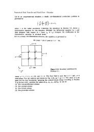
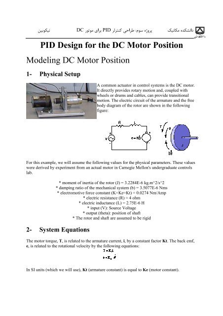
1- Physical Setup<br />
A common actuator in control systems is <strong>the</strong> <strong>DC</strong> motor.<br />
It directly provides rotary motion and, coupled with<br />
wheels or drums and cables, can provide transitional<br />
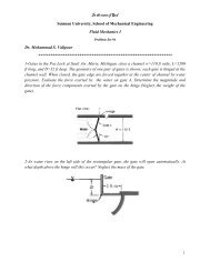
motion. The electric circuit of <strong>the</strong> armature and <strong>the</strong> free<br />
body diagram of <strong>the</strong> rotor are shown in <strong>the</strong> following<br />
figure:<br />
For this example, we will assume <strong>the</strong> following values <strong>for</strong> <strong>the</strong> physical parameters. These values<br />
were derived by experiment from an actual motor in Carnegie Mellon's undergraduate controls<br />
lab.<br />
* moment of inertia of <strong>the</strong> rotor (J) = 3.2284E-6 kg.m^2/s^2<br />
* damping ratio of <strong>the</strong> mechanical system (b) = 3.5077E-6 Nms<br />
* electromotive <strong>for</strong>ce constant (K=Ke=Kt) = 0.0274 Nm/Amp<br />
* electric resistance (R) = 4 ohm<br />
* electric inductance (L) = 2.75E-6 H<br />
* input (V): Source Voltage<br />
* output (<strong>the</strong>ta): position of shaft<br />
* The rotor and shaft are assumed to be rigid<br />
2- System Equations<br />
The motor torque, T, is related to <strong>the</strong> armature current, i, by a constant factor Kt. The back emf,<br />
e, is related to <strong>the</strong> rotational velocity by <strong>the</strong> following equations:<br />
In SI units (which we will use), Kt (armature constant) is equal to Ke (motor constant).
<strong>DC</strong> <strong>PID</strong> : <br />
<br />
From <strong>the</strong> figure above we can write <strong>the</strong> following equations based on Newton's law combined<br />
with Kirchhoff's law:<br />
1. Transfer Function<br />
Using Laplace Trans<strong>for</strong>ms <strong>the</strong> above equations can be expressed in terms of s.<br />
By eliminating I(s) we can get <strong>the</strong> following transfer function, where <strong>the</strong> rotating speed is <strong>the</strong><br />
output and <strong>the</strong> voltage is an input.<br />
However during this example we will be looking at <strong>the</strong> position, as being <strong>the</strong> output. We can<br />
obtain <strong>the</strong> position by integrating Theta Dot, <strong>the</strong>re<strong>for</strong>e we just need to divide <strong>the</strong> transfer<br />
function by s.<br />
2. State Space<br />
These equations can also be represented in state-space <strong>for</strong>m. If we choose motor position, motor<br />
speed, and armature current as our state variables, we can write <strong>the</strong> equations as follows:<br />
J=3.2284E-6;<br />
b=3.5077E-6;<br />
K=0.0274;<br />
R=4;<br />
L=2.75E-6;<br />
num=K;<br />
den=[(J*L) ((J*R)+(L*b)) ((b*R)+K^2) 0];
<strong>DC</strong> <strong>PID</strong> : <br />
<br />
.! " ! #" $% & ' ! () ) * +, -. /. $&0 1 !2.0 <br />
:7 .<br />
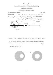
7 89 kp=1.7, kd=0,ki=0 1 .<br />
%/. -. 4 %/ $* 56<br />
.<br />
%" ! ;< / ; "
<strong>DC</strong> <strong>PID</strong> : <br />
<br />
.<br />
%" ! ;< => ; -. : 4
<strong>DC</strong> <strong>PID</strong> : <br />
<br />
:* " %/ 1 ;A ; - -? ;@ ; <strong>PID</strong> -19<br />
We will want to be able to position <strong>the</strong> motor very precisely, thus <strong>the</strong> steady-state error of <strong>the</strong><br />
motor position should be zero. We will also want <strong>the</strong> steady-state error due to a disturbance, to<br />
be zero as well. The o<strong>the</strong>r per<strong>for</strong>mance requirement is that <strong>the</strong> motor reaches its final position<br />
very quickly. In this case, we want it to have a settling time of 50ms. We also want to have an<br />
overshoot smaller than 10%. If we simulate <strong>the</strong> reference input (R) by a unit step input, <strong>the</strong>n <strong>the</strong><br />
motor speed output should have:<br />
Settling time less than 50 milliseconds, Overshoot less than 10% , No steady-state error, No<br />
steady-state error due to a disturbance, Settling time of disturbance rejection less than 60<br />
milliseconds<br />
/ ;7 -7. : ; D % .! ? B / ; -. : E% F;< <br />
;7 -. : -1 ;< ; -. : -1 #G21 ; ; 1 H / ;I<br />
;7 7A G7 E% J ; / ;I I< / % ! % .<br />
8<br />
.<br />
* 1A J A