Tests of Two Three-Story Ductile Steel Plate Shear Walls
Tests of Two Three-Story Ductile Steel Plate Shear Walls
Tests of Two Three-Story Ductile Steel Plate Shear Walls

You also want an ePaper? Increase the reach of your titles
YUMPU automatically turns print PDFs into web optimized ePapers that Google loves.
Structures 2008: Crossing Borders<br />
© 2008 ASCE<br />
<strong>Tests</strong> <strong>of</strong> <strong>Two</strong> <strong>Three</strong>-<strong>Story</strong> <strong>Ductile</strong> <strong>Steel</strong> <strong>Plate</strong> <strong>Shear</strong> <strong>Walls</strong><br />
Authors:<br />
Saied Sabouri-Ghomi, K.N.T. University <strong>of</strong> Technology, Tehran, Iran, sabouri@kntu.ac.ir<br />
Majid Gholhaki, Semnan University, Semnan, Iran, mgholhaki@semnan.ac.ir<br />
ABSTRACT<br />
<strong>Two</strong> three-story unstiffened ductile steel plate shear walls were tested under cyclic loading.<br />
The shear walls had two types <strong>of</strong> beam-to-column connections consisting <strong>of</strong> rigid (SPSW-R)<br />
and simple (SPSW-S). Low and high strengths steel were used in the plates <strong>of</strong> panels and<br />
boundary frames, respectively. Both specimens endured many cycles <strong>of</strong> loading most <strong>of</strong><br />
which were in the inelastic range. They showed excellent ductility and energy dissipation<br />
characteristics and exhibited stable behavior at very large deformations.<br />
KEY WORDS<br />
Thin <strong>Steel</strong> <strong>Plate</strong> <strong>Shear</strong> Wall, Low Strength <strong>Steel</strong>, Hysteretic Behavior, Beam-to-Column<br />
Connection.<br />
INTRODUCTION<br />
During the past 3 decades, interest has grown globally in the application <strong>of</strong> steel plate shear<br />
walls (SPSWs) as lateral load resisting system. The system consists <strong>of</strong> steel plates one story<br />
high and one bay wide connected to the adjacent beams and columns. The plates are installed<br />
in one or more bays for the full height <strong>of</strong> a building, thereby forming a stiff cantilever wall<br />
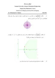
(e.g. Figure 1).<br />
FIGURE 1 - OVERALL SHAPE OF SPSW (COURTESY OF M. GILMORE)<br />
The beam-to-column connections may be rigid or simple in the surrounding steel frame,<br />
depending on the design philosophy. <strong>Steel</strong> plate shear walls are well-suited for either new<br />
construction or as a means for the seismic upgrading <strong>of</strong> existing steel and concrete structures.<br />
1
Structures 2008: Crossing Borders<br />
© 2008 ASCE<br />
SPSWs possess properties that are fundamentally beneficial to resisting seismically<br />
induced loads. As is demonstrated herein, these include superior ductility, robust resistance to<br />
degradation under cyclic loading, high initial stiffness, and inherent redundancy and<br />
significant energy dissipation.<br />
Until the 1980s, the design limit state for SPSW in North America was out-<strong>of</strong>-plane<br />
buckling <strong>of</strong> the infill plates. Although it has been shown that stiffening the panel heavily can<br />
increase the amount <strong>of</strong> energy dissipated under cyclic loading significantly [1], the cost<br />
involved is likely to be prohibitive in most markets. However, it has been known for a long<br />
time that buckling does not necessarily represent the limit <strong>of</strong> useful behavior and there is<br />
considerable post buckling strength in an unstiffened shear panel [2].<br />
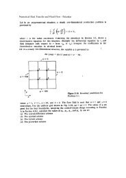
At the point <strong>of</strong> critical elastic buckling, the load-resisting mechanism changes from inplane<br />
shear to an inclined tension field. Finally by yielding <strong>of</strong> the steel panel significant<br />
amount <strong>of</strong> energy dissipate in cyclic loading.<br />
In recent years, SPSWs have been used in a number <strong>of</strong> buildings as part <strong>of</strong> the lateral load<br />
resisting system, mainly in Japan and North America. One <strong>of</strong> the most significant buildings<br />
constructed with SPSWs, in a highly seismic area, is a 35-story high-rise building in Kobe,<br />
Japan (e.g. Figure 2).<br />
FIGURE 2 - 35-STORY KOBE BUILDING (COURTESY OF C.E. VENTURA)<br />
This structure was constructed in 1988 and performed very well during the 1995 Kobe<br />
earthquake, [3]. The 24-story U.S. Courthouse building in Seattle, Washington, and 6-story<br />
building in Saint Georges, Quebec, are prime examples <strong>of</strong> the application <strong>of</strong> this system in the<br />
United States and Canada, (e.g. Figures 3 and 4, respectively).<br />
PREVIOUS TESTING OF STEEL PLATE SHEAR WALLS<br />
The studies so far is limited to the topic <strong>of</strong> physical testing <strong>of</strong> unstiffened SPSWs. Timler and<br />
Kulak [4] tested a single-story SPSW to verify the analytical technique established by<br />
Thorburn et al. [5].<br />
Tromposch and Kulak [6] tested a shear wall similar to the test undertaken by Timler and<br />
Kulak [4]. However, important modifications were introduced, including the use <strong>of</strong> bolted<br />
simple connections in the frame, a thinner infill panel, and very stiff beam members.<br />
An experimental program conducted by Elgaaly and Caccese [7] investigated the behavior<br />
<strong>of</strong> ten one-quarter scale SPSW models subjected to cyclic loading. The specimens were three<br />
2
Structures 2008: Crossing Borders<br />
© 2008 ASCE<br />
stories high and one bay wide. Parameters that varied were the panel thickness and the beamto-column<br />
connection in both rigid and simple types.<br />
FIGURE 3 - 24-STORY COURTHOUSE BUILDING, SEATTLE, WASHINGTON (COURTESY OF F.<br />
OOMS)<br />
FIGURE 4 - 6-STORY SPSW DURING CONSTRUCTION, QUEBEC, CANADA (COURTESY OF M.<br />
GILMORE)<br />
Sabouri-Ghomi and Roberts [8] and Roberts and Sabouri-Ghomi [9] conducted a series <strong>of</strong><br />
small scale quasi-static cyclic tests on slender unstiffened shear panels. Twelve different<br />
specimens with infill panel dimensions <strong>of</strong> 300 mm by 300 mm and 450 mm by 300 mm were<br />
tested. Infill plate thicknesses were 0.54 mm and 0.83 mm <strong>of</strong> steel and 1.23 mm <strong>of</strong> aluminum.<br />
Driver [10] tested a half-scaled four-story SPSW frame under quasi-static cyclic loading<br />
utilizing full rigid connections. The objective <strong>of</strong> this test was to study the performance <strong>of</strong> a<br />
multi-story SPSW under the effects <strong>of</strong> very sever cyclic loading.<br />
Lubell [11] conducted cyclic tests on two single panel specimens and one four-story<br />
specimen. Each specimen was tested under fully reversed quasi-static cyclic loading in both<br />
its elastic and inelastic response regions.<br />
Rezai [12] conducted a shake table test on a four-story steel plate shear wall specimen.<br />
The scale for the SPSW was a factor <strong>of</strong> 1 4 and the thickness <strong>of</strong> the infill steel panels was 1.5<br />
mm. The limited capacity <strong>of</strong> the shake table prevented a significant inelastic response from<br />
the specimen.<br />
3
Structures 2008: Crossing Borders<br />
© 2008 ASCE<br />
Astaneh-Asl and Zhao [13] conducted two half-scale three-story SPSW tests under cyclic<br />
loading. The specimens were one-half <strong>of</strong> a coupled wall with concrete-filled hollow steel<br />
section as columns and had a total height <strong>of</strong> 6.2 m. The specimens showed good displacement<br />
ductility capacity and stable hysteresis behavior with desirable energy dissipation<br />
characteristics.<br />
Behbahani-Fard [14] conducted a large-scale test on a three-story SPSW specimen under<br />
lateral quasi-static cyclic loading in the presence <strong>of</strong> gravity loads. The specimen formed the<br />
upper part <strong>of</strong> a four-story SPSW that had been tested earlier by Driver [10]. Since the test<br />
specimen had gone through a history <strong>of</strong> plastic deformation from previous testing by Driver<br />
[10], evaluating the effect <strong>of</strong> the previous test on the overall performance <strong>of</strong> the specimen was<br />
one <strong>of</strong> the objectives.<br />
Vian and Bruneau [15] conducted three SPSW specimen tests made <strong>of</strong> low yield strength<br />
(LYS) steel infill panels and reduced beam sections (RBS) at the beam-ends, under cyclic<br />
loading. <strong>Two</strong> <strong>of</strong> the specimens had holes for allowing mechanical utilities to pass through.<br />
Multiple holes were designed in the steel plate <strong>of</strong> the panel used in the first specimen that<br />
reduced the overall strength compared to the panel without perforations. The second<br />
perforated SPSW specimen was designed with quarter-circle cut-outs in the panel corners<br />
which were reinforced to transfer panel forces to the adjacent frame.<br />
Kharrazi [16] conducted two SPSW specimen tests. The infill panels in these specimens<br />
were made <strong>of</strong> low yield strength and mild steel. They had the ratio <strong>of</strong> height to width more<br />
than one. The overall strength, elastic post-buckling stiffness and post-yield stiffness were<br />
very high.<br />
SPECIMENS DETAILS AND TESTS SETUP<br />
Figure 5 shows the schematic representation <strong>of</strong> two test specimens SPSW-R and SPSW-S that<br />
differ principally in type <strong>of</strong> beam-to-column connections, [17].<br />
FIGURE 5 - SCHEMATIC REPRESENTATION OF SPECIMENS SPSW-R AND SPSW-S<br />
4
Structures 2008: Crossing Borders<br />
© 2008 ASCE<br />
Figures 6 and 7 show the rigid and simple types <strong>of</strong> beam-to-column connections which<br />
were used for specimens SPSW-R and SPSW-S, respectively.<br />
The beam-to-column connections <strong>of</strong> top beams in both specimens SPSW-R and SPSW-S<br />
were rigid.<br />
FIGURE 6 - DETAILS OF RIGID BEAM-TO-COLUMN CONNECTION<br />
All beams were selected such that out-<strong>of</strong>-plane buckling would not occur, eliminating the<br />
need for intermediate lateral bracing. In order to preclude probability <strong>of</strong> out-<strong>of</strong>-plane buckling<br />
<strong>of</strong> wall, the lateral supporting system were used at each beam level. The lateral supporting<br />
system consisted <strong>of</strong> three double beams, with both ends connected to the main supporting<br />
frame system.<br />
Both specimens were designed by plate-frame-interaction (PFI) technique, developed by<br />
Sabouri-Ghomi and Roberts [8, 9, 18, and 19] for analysis and design <strong>of</strong> steel plate shear<br />
walls. In addition, all requirements <strong>of</strong> AISC code for frames were met.<br />
FIGURE 7 - DETAILS OF SIMPLE BEAM-TO-COLUMN CONNECTION<br />
The mean measured thickness and the panel aspect ratio (width/height) for all panels are<br />
0.7 mm and 1.0, respectively.<br />
Equal horizontal load was applied at the top <strong>of</strong> specimens. Because <strong>of</strong> the laboratory<br />
limitations, only two hydraulic pressure jacks were used at both sides <strong>of</strong> the top level in each<br />
specimen.<br />
For analysis and design <strong>of</strong> specimens in addition to the use <strong>of</strong> PFI technique [20,21,22]<br />
for analysis and design <strong>of</strong> specimens, preliminary finite elements analyses were also carried<br />
5
Structures 2008: Crossing Borders<br />
© 2008 ASCE<br />
out using the commercial general-purpose finite elements s<strong>of</strong>tware ANSYS. Because the<br />
computational demands on this system were high due to shear-buckling and localized<br />
instabilities in the infill plate, monotonic loading was used to estimate the envelope <strong>of</strong> loaddisplacement<br />
response.<br />
TEST PROCEDURES AND LOADING PROTOCOL<br />
Numerous load and deflection histories could be used to evaluate a structural component for<br />
seismic performance. Most slow cyclic tests that are intended to simulate earthquake loading<br />
employ a horizontal in-plane load history that uses gradually increasing loads or<br />
displacements in successive cycles.<br />
Based on ATC-24 [23] for specimen SPSW-R, the yield displacement ( y ) in panel 1 was<br />
determined during the early stages <strong>of</strong> the test as 2.44 mm. Prior to reaching this value, single<br />
loading cycles leading to shears in panel 1 <strong>of</strong> 10.3 kN, 12.8 kN and 15.2 kN and three<br />
cycles each with shears <strong>of</strong> 18.0 kN were conducted to explore the elastic and the initial<br />
inelastic behavior. These constituted cycles 1-6. After cycles 7, 8, and 9 with a displacement<br />
<strong>of</strong> y =2.44 mm, the displacement in the first story was increased by 2.44 mm in each<br />
subsequent deformation step. Following the guidelines <strong>of</strong> ATC-24, three cycles were<br />
conducted at each deformation setup to a deformation <strong>of</strong> 3 y (cycles 13-15) and two cycles at<br />
each deformation setup with incremental deformation <strong>of</strong> y thereafter.<br />
After testing SPSW-R, the loading strategy was changed for specimen SPSW-S. The yield<br />
displacement ( y ) in panel 1 <strong>of</strong> specimen SPSW-S, was determined during the early stages <strong>of</strong><br />
the test as 3.09 mm. Prior to reaching this value, six cycles similar to specimen SPSW-R and<br />
with the same amplitudes were conducted to explore the elastic and the initial inelastic<br />
behavior <strong>of</strong> specimen SPSW-S. After cycles 7, 8 and 9 with a displacement <strong>of</strong> y =3.09 mm,<br />
two cycles were conducted at each displacement set-up with incremental displacement <strong>of</strong> 2 y<br />
up to cycle 17. In cycles 18 and 19 the displacement reached 10 y and 11 y , respectively.<br />
BEHAVIOR OF SPECIMENS<br />
The behaviors <strong>of</strong> specimens during the tests were as follow:<br />
Specimen SPSW-R<br />
Specimen SPSW-R before the test is shown in Fig. 8. During the 6 initial cycles, an<br />
inspection <strong>of</strong> the thin infill panels and boundary members revealed that no yielding had<br />
occurred. In cycle 7 (the first cycle with y 2.44mm<br />
that y is the first yielding in<br />
specimen); the existing yield patterns became considerably more pronounced.<br />
In this cycle panels 2 and 3, buckled visibly at maximum displacement. In addition,<br />
several loud bangs first occurred in this cycle as the plate buckles popped out and reoriented<br />
themselves upon reversal <strong>of</strong> the loading direction. These noises continued to occur in all<br />
subsequent cycles.<br />
During the cycles 10-12, as loading continued, amplitude <strong>of</strong> the buckles in the second and<br />
third story panels increased. After unloading the forces, residual buckles were clearly visible<br />
in a complex surface geometry that did not favor the orientation that formed in either direction<br />
<strong>of</strong> loading. In cycle 13, the sign <strong>of</strong> beam yielding was observed in panel 2.<br />
6
Structures 2008: Crossing Borders<br />
© 2008 ASCE<br />
FIGURE 8 - OVERALL PANELS OF SPECIMEN SPSW-R<br />
The first tear was detected during cycle 21 in the east top corner <strong>of</strong> plate <strong>of</strong> panel 2 near<br />
the pins (e.g. Figure 9). This tear propagated during subsequent cycles. After, the transverse<br />
welding <strong>of</strong> the L shape which was used as fish plate conjunction near the second beam<br />
cracked.<br />
FIGURE 9 - FIRST TEARING OF SPSW-R IN CYCLE 21<br />
In cycle 26, the crack <strong>of</strong> beam-to-column connection <strong>of</strong> second beam was increased. In<br />
addition, transverse welding <strong>of</strong> horizontal and vertical L shape conjunction at top east corner<br />
in panel 1 and bottom corners <strong>of</strong> panels 2 and 3 were cracked. Also, during cycle 26, at a<br />
displacement <strong>of</strong> 9 y in panel 1, the maximum base shear <strong>of</strong> 153 kN was reached. The load-<br />
7
Structures 2008: Crossing Borders<br />
© 2008 ASCE<br />
carrying capacity <strong>of</strong> the test specimen declined very gradually during each <strong>of</strong> the remaining<br />
cycles <strong>of</strong> increasing deformations.<br />
In cycle 27, the amplitude <strong>of</strong> the buckles in all panels increased. For example, the<br />
amplitude <strong>of</strong> the buckle in panel 2 was estimated to be about 130 mm from the neutral<br />
position. In cycles 29 and 30, in top and east edges <strong>of</strong> panel 2 and in bottom and west edges <strong>of</strong><br />
panel 3 the tearing around pins began and increased. In these cycles because <strong>of</strong> weakness <strong>of</strong><br />
the plate action and consequently serious frame action, the weld <strong>of</strong> conjunction beam flanges<br />
to column flange in levels 1 and 2 were fractured and crack propagated and moved to the web<br />
<strong>of</strong> beams.<br />
Beginning at cycle 31, when the displacement <strong>of</strong> panel 1 reached 11 y , tears in the<br />
interior <strong>of</strong> the panels 2 and 3 near the L shape suddenly formed as a result <strong>of</strong> kinking <strong>of</strong> the<br />
stretched plate during load reversals. During the first loading history <strong>of</strong> cycle 31, and just<br />
prior to failure, the base shear reached 91% <strong>of</strong> the maximum base shear reached in cycle 26.<br />
The stiffness <strong>of</strong> the shear panel itself was declining in a very gradual and stable manner, and it<br />
maintained its integrity to the end <strong>of</strong> the test.<br />
Up to the end <strong>of</strong> the test all columns remained undamaged and there were no signs <strong>of</strong> local<br />
or global buckling in them. Also no tearing occurred in panel 1 and there were no fracture in<br />
the column s toe due to good performance <strong>of</strong> the toe stiffeners.<br />
Figure 10 shows the behavior <strong>of</strong> specimen SPSW-R during the test.<br />
FIGURE 10 - HYSTERETIC BEHAVIOR OF SPECIMEN SPSW-R<br />
Specimen SPSW-S<br />
During the 6 initial cycles, an inspection <strong>of</strong> the infill panels and boundary members revealed<br />
that no yielding had occurred. In cycle 7 (the first cycle with y 3.09mm<br />
that y is the<br />
first yielding in specimen), the existing yield patterns, became considerably more pronounced.<br />
Panels 2 and 3, buckled visibly at the maximum displacement. In addition, several load bangs<br />
first occurred in this cycle as the plate buckles popped out and oriented themselves upon<br />
reversal <strong>of</strong> the loading direction. These noises continued to occur in all subsequent cycles.<br />
In cycles 8 and 9, some flaking <strong>of</strong> the white-wash paint on the plates <strong>of</strong> panels, near the<br />
conjunction <strong>of</strong> horizontal and vertical L shape, used as fish plate <strong>of</strong> panels 1 and 2, were<br />
noted. Minor signs <strong>of</strong> yielding also occurred in plates <strong>of</strong> the corresponding panels. During<br />
cycles 10 and 11, as loading continued, amplitude <strong>of</strong> the buckles in the second and third<br />
panels increased. In addition, the yielded areas on the plates <strong>of</strong> all panels had grown larger. In<br />
cycles 12 and 13, flaking increased in top west <strong>of</strong> panel 2 and bottom west <strong>of</strong> panel 3 and in L<br />
8
Structures 2008: Crossing Borders<br />
© 2008 ASCE<br />
shape connected between beam web and column flange flaking <strong>of</strong> white-wash was started.<br />
The first tear was detected during cycle 14 in the east bottom corner <strong>of</strong> plate near the L shape<br />
in panel 2, (e.g. Figure 11).<br />
FIGURE 11 - FIRST TEARING OF SPSW-S IN CYCLE 14<br />
During the cycles 15, 16 and 17 the flaking <strong>of</strong> the white-wash paint propagated all over<br />
the panels 2, 3 and to some extent in panel 1. In cycle 18, at a displacement <strong>of</strong> 10 y in panel<br />
1, the maximum base shear <strong>of</strong> 121 kN was reached. The load-carrying capacity <strong>of</strong> the test<br />
specimen reached rapidly during the remaining cycles.<br />
Beginning at cycle 19, when the displacement <strong>of</strong> panel 1 reached 11 y first in the top<br />
edge and then in the east edge <strong>of</strong> plate in panel 2, tearing formed suddenly as a result <strong>of</strong><br />
kinking <strong>of</strong> the stretched plate during load reversals. During the second loading history <strong>of</strong><br />
cycle 19, and just prior to failure, the base shear reached 68% <strong>of</strong> the maximum base shear<br />
obtained in cycle 18. Because <strong>of</strong> the tearing <strong>of</strong> panel 2, the rotation <strong>of</strong> beams 1 and 2 reached<br />
maximum and so, the L shape pr<strong>of</strong>ile connected between web <strong>of</strong> beam and flange <strong>of</strong> column<br />
was yielded. At the end <strong>of</strong> cycle 19, tearing started at the top east corner <strong>of</strong> plate in panel 1.<br />
Like the test <strong>of</strong> SPSW-R, up to the end <strong>of</strong> the test, all columns remained undamaged and there<br />
were no signs <strong>of</strong> local or global buckling in them. Also, there was no fracture in the column s<br />
toe because <strong>of</strong> the good performance <strong>of</strong> the toe stiffeners.<br />
Figure 12 shows the behavior <strong>of</strong> specimen SPSW-S during the test.<br />
SUMMARY<br />
The hysteretic behaviors <strong>of</strong> both specimens indicated that the shear wall configurations tested<br />
possess an extremely high degree <strong>of</strong> ductility. The results showed that the ductility factor <strong>of</strong><br />
specimens SPSW-R and SPSW-S are 6.63 and 8.24, respectively.<br />
The results <strong>of</strong> the tested specimens showed that the steel plate shear walls, which are<br />
designed based on the PFI technique and low strength steel plates are used in their panels<br />
according to the general concept <strong>of</strong> easy-going steel in which the low strength plate absorbs<br />
9
Structures 2008: Crossing Borders<br />
© 2008 ASCE<br />
much more energy in smaller displacement compared to the high strength boundary steel<br />
frame, are more ductile. As it was observed from the tests, in such walls, the columns can be<br />
protected from any damage.<br />
FIGURE 12 - HYSTERETIC BEHAVIOR OF SPECIMEN SPSW-S<br />
The hysteresis curves <strong>of</strong> specimens showed that the effect <strong>of</strong> beam-to-column connection<br />
type on the initial stiffness <strong>of</strong> thin steel plate shear walls is negligible but it effects on<br />
specimens' strengths.<br />
The results showed that in specimen SPSW-R the amount <strong>of</strong> energy dissipated during the<br />
loading cycles was significantly greater than those in SPSW-S.<br />
The results showed that, in effect <strong>of</strong> the presence <strong>of</strong> infill plate, there is a reduction in<br />
reliance on the beam-to-column connection <strong>of</strong> the frame for resisting the story shears.<br />
Therefore, the joint panel zone would not generally be a critical element. It is likely that it<br />
could be designed to remain essentially elastic.<br />
REFRENCES<br />
[1] Takahashi, Y., Takemoto, Y., Takeda, T., and Takagi, M., Experimental Study on Thin <strong>Steel</strong> <strong>Shear</strong><br />
<strong>Walls</strong> and Particular Bracings under Alternative Horizontal Load , Preliminary Report, IABSE<br />
Symposium on Resistance and Ultimate Deformability <strong>of</strong> Structures Acted on Well-defined Repeated<br />
Loads, Lisbon, Portugal, 1973,185-191.<br />
[2] Wagner, H., Flat Sheet Metal Girders with Very Thin Webs, Part I-General Theories and Assumptions ,<br />
Tech. Memo., No. 604, National Advisory Committee for Aeronautics, Washington, D. C., 1931.<br />
[3] Astaneh-Asl, A., Seismic Behavior and Design <strong>of</strong> <strong>Steel</strong> <strong>Shear</strong> <strong>Walls</strong> , <strong>Steel</strong> Tips Report, Structural <strong>Steel</strong><br />
Educational Council, July, Moraga, CA., 2001.<br />
[4] Timler, P. A. and Kulak, G. L., Experimental Study <strong>of</strong> <strong>Steel</strong> <strong>Plate</strong> <strong>Shear</strong> <strong>Walls</strong> , Structural Engineering<br />
Report No. 114, Dept. <strong>of</strong> Civil Engineering, University <strong>of</strong> Alberta, Edmonton, Alta., Canada, 1983.<br />
[5] Thorburn, L. J., Kulak, G. L., and Montgomery, C. J., Analysis <strong>of</strong> <strong>Steel</strong> <strong>Plate</strong> <strong>Shear</strong> <strong>Walls</strong> , Structural<br />
Engineering Report No. 107, Dept. <strong>of</strong> Civil Engineering, University <strong>of</strong> Alberta, Edmonton, Alta., Canada,<br />
1983.<br />
[6] Tromposch, E. W. and Kulak, G. L., Cyclic and Static Behavior <strong>of</strong> Thin Panel <strong>Steel</strong> <strong>Plate</strong> <strong>Shear</strong> <strong>Walls</strong> ,<br />
Structural Engineering Rep. No. 145, Dept. <strong>of</strong> Civil Engineering, University <strong>of</strong> Alberta, Edmonton, Alta.,<br />
Canada, 1987.<br />
[7] Elgaaly, M., and Caccese, V., <strong>Steel</strong> <strong>Plate</strong> <strong>Shear</strong> <strong>Walls</strong> , Proceeding <strong>of</strong> AISC National <strong>Steel</strong> Construction<br />
10
Structures 2008: Crossing Borders<br />
© 2008 ASCE<br />
Conference, American Institute <strong>of</strong> <strong>Steel</strong> Construction (AISC), Inc., Chicago, 1990.<br />
[8] Sabouri-Ghomi, S., and Roberts, T.M., Nonlinear Dynamic Analysis <strong>of</strong> Thin <strong>Steel</strong> <strong>Plate</strong> <strong>Shear</strong> <strong>Walls</strong> ,<br />
Computers and Structures, 39(1/2), 1991, 121 127.<br />
[9] Roberts, T. M., and Sabouri-Ghomi, S., Hysteretic Characteristics <strong>of</strong> Unstiffened <strong>Plate</strong> <strong>Shear</strong> Panels ,<br />
Thin-Walled Structures, 12, 1991, 145 162.<br />
[10] Driver, R. G., Seismic Behavior <strong>of</strong> <strong>Steel</strong> <strong>Plate</strong> <strong>Shear</strong> <strong>Walls</strong> , Ph.D. Dissertation, Department <strong>of</strong> Civil<br />
and Environmental Engineering, University <strong>of</strong> Alberta, Edmonton, AB, 1997.<br />
[11] Lubell, A. S., Performance <strong>of</strong> Unstiffened <strong>Steel</strong> <strong>Plate</strong> <strong>Shear</strong> <strong>Walls</strong> under Cyclic Quasi Static Loading ,<br />
M.A.Sc. Thesis, Department <strong>of</strong> Civil Engineering, University <strong>of</strong> British Columbia, Vancouver, BC,<br />
Canada, 1997.<br />
[12] Rezai, M., Seismic Behavior <strong>of</strong> <strong>Steel</strong> <strong>Plate</strong> <strong>Shear</strong> <strong>Walls</strong> by Shake Table Testing , Ph.D. Dissertation,<br />
Department <strong>of</strong> Civil Engineering, University <strong>of</strong> British Columbia, Vancouver, BC, Canada, 1999.<br />
[13] Astaneh-Asl, A. and Zhao, Q., Cyclic Behavior <strong>of</strong> <strong>Steel</strong> <strong>Shear</strong> Wall Systems , Proceedings <strong>of</strong> Annual<br />
Stability Conference, Structural Stability Research Council, Seattle, 2002.<br />
[14] Behbahani-Fard, M. R., Cyclic Behavior <strong>of</strong> Unstiffened <strong>Steel</strong> <strong>Plate</strong> <strong>Shear</strong> <strong>Walls</strong> , Ph.D. Dissertation,<br />
University <strong>of</strong> Alberta, 2003, 227 pages.<br />
[15] Vian, D. and Bruneau, M., Testing <strong>of</strong> Special LYS <strong>Steel</strong> <strong>Plate</strong> <strong>Shear</strong> <strong>Walls</strong> , Proceedings <strong>of</strong> the 13th<br />
World Conference on Earthquake Engineering, Paper No. 978, Vancouver, British Columbia, Canada,<br />
2004.<br />
[16] Kharrazi, M. H. K., Rational Method for Analysis and Design <strong>of</strong> <strong>Steel</strong> <strong>Plate</strong> <strong>Shear</strong> <strong>Walls</strong> , Ph.D.<br />
Dissertation, University <strong>of</strong> British Colombia, 2005, 217 pages.<br />
[17] Sabouri-Ghomi, S. and Gholhaki, M., Cyclic <strong>Tests</strong> on <strong>Two</strong> <strong>Three</strong>-<strong>Story</strong> <strong>Ductile</strong> <strong>Steel</strong> <strong>Plate</strong> <strong>Shear</strong><br />
<strong>Walls</strong> , Report No.31, Building and Housing Research Center (BHRC), 2006, 117 pages.<br />
[18] Roberts, T. M. and Sabouri-Ghomi, S., Hysteretic Characteristics <strong>of</strong> Unstiffened Perforated <strong>Steel</strong> <strong>Plate</strong><br />
<strong>Shear</strong> Panels , Thin-Walled Structures, 14, 1992, 139 151.<br />
[19] Sabouri-Ghomi, S. and Roberts, T. M., Nonlinear Dynamic Analysis <strong>of</strong> <strong>Steel</strong> <strong>Plate</strong> <strong>Shear</strong> <strong>Walls</strong><br />
Including <strong>Shear</strong> and Bending Deformations , Engineering Structures, 14(5), 1992, 309 317.<br />
[20] Sabouri-Ghomi, S., Lateral Load Resisting Systems: An Introduction to <strong>Steel</strong> <strong>Shear</strong> <strong>Walls</strong> , Anguizeh<br />
Publishing Ltd., Tehran, Iran, 2002.<br />
[21] Sabouri-Ghomi, S., Ventura, C. E. and Kharrazi, M. H. K., <strong>Shear</strong> Analysis and Design <strong>of</strong> <strong>Ductile</strong> <strong>Steel</strong><br />
<strong>Plate</strong> <strong>Shear</strong> <strong>Walls</strong> , Journal <strong>of</strong> Structural Engineering, ASCE, 131(6), 2005, 878-889.<br />
Sabouri-Ghomi, S, Lateral Load Resisting Systems: An Innovative Idea to Application <strong>of</strong> Easy-Going<br />
[22]<br />
<strong>Steel</strong> , Anguizeh Publishing Ltd., Tehran, Iran, 2004.<br />
ATC , Guidelines for Seismic Testing <strong>of</strong> Components <strong>of</strong> <strong>Steel</strong> Structures , Applied Technology Council,<br />
[23]<br />
Report 24, 1992.<br />
11