proform 955r - Fitness Equipment
proform 955r - Fitness Equipment
proform 955r - Fitness Equipment

Create successful ePaper yourself
Turn your PDF publications into a flip-book with our unique Google optimized e-Paper software.
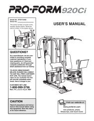
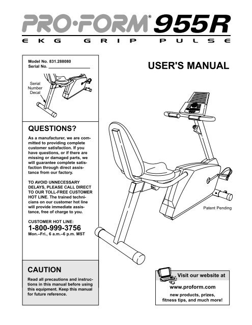
Model No. 831.288080<br />
Serial No.<br />
USER'S MANUAL<br />
Serial<br />
Number<br />
Decal<br />
QUESTIONS?<br />
As a manufacturer, we are committed<br />
to providing complete<br />
customer satisfaction. If you<br />
have questions, or if there are<br />
missing or damaged parts, we<br />
will guarantee complete satisfaction<br />
through direct assistance<br />
from our factory.<br />
TO AVOID UNNECESSARY<br />
DELAYS, PLEASE CALL DIRECT<br />
TO OUR TOLL-FREE CUSTOMER<br />
HOT LINE. The trained technicians<br />
on our customer hot line<br />
will provide immediate assistance,<br />
free of charge to you.<br />
Patent Pending<br />
CUSTOMER HOT LINE:<br />
1-800-999-3756<br />
Mon.–Fri., 6 a.m.–6 p.m. MST<br />
CAUTION<br />
Read all precautions and instructions<br />
in this manual before using<br />
this equipment. Keep this manual<br />
for future reference.<br />
Visit our website at<br />
www.<strong>proform</strong>.com<br />
new products, prizes,<br />
fitness tips, and much more!
TABLE OF CONTENTS<br />
IMPORTANT PRECAUTIONS . . . . . . . . . . . . . . . . . . . . . . . . . . . . . . . . . . . . . . . . . . . . . . . . . . . . . . . . . . . . .2<br />
BEFORE YOU BEGIN . . . . . . . . . . . . . . . . . . . . . . . . . . . . . . . . . . . . . . . . . . . . . . . . . . . . . . . . . . . . . . . . . . .3<br />
ASSEMBLY . . . . . . . . . . . . . . . . . . . . . . . . . . . . . . . . . . . . . . . . . . . . . . . . . . . . . . . . . . . . . . . . . . . . . . . . . . .4<br />
HOW TO OPERATE THE RECUMBENT CYCLE . . . . . . . . . . . . . . . . . . . . . . . . . . . . . . . . . . . . . . . . . . . . . . .8<br />
MAINTENANCE AND TROUBLE-SHOOTING . . . . . . . . . . . . . . . . . . . . . . . . . . . . . . . . . . . . . . . . . . . . . . . .12<br />
EXERCISE GUIDELINES . . . . . . . . . . . . . . . . . . . . . . . . . . . . . . . . . . . . . . . . . . . . . . . . . . . . . . . . . . . . . . . .13<br />
PART LIST . . . . . . . . . . . . . . . . . . . . . . . . . . . . . . . . . . . . . . . . . . . . . . . . . . . . . . . . . . . . . . . . . . . . . . . . . . .14<br />
EXPLODED DRAWING . . . . . . . . . . . . . . . . . . . . . . . . . . . . . . . . . . . . . . . . . . . . . . . . . . . . . . . . . . . . . . . . .15<br />
HOW TO ORDER REPLACEMENT PARTS . . . . . . . . . . . . . . . . . . . . . . . . . . . . . . . . . . . . . . . . . . .Back Cover<br />
FULL 90 DAY WARRANTY . . . . . . . . . . . . . . . . . . . . . . . . . . . . . . . . . . . . . . . . . . . . . . . . . . . . . . .Back Cover<br />
IMPORTANT PRECAUTIONS<br />
WARNING: To reduce the risk of serious injury, read the following important precautions<br />
before using the recumbent cycle.<br />
1. Read all instructions in this manual before<br />
using the recumbent cycle.<br />
2. It is the responsibility of the owner to ensure<br />
that all users of the recumbent cycle are adequately<br />
informed of all precautions. Use the<br />
recumbent cycle only as described in this<br />
manual.<br />
3. Use the recumbent cycle indoors on a level<br />
surface. Keep the recumbent cycle away from<br />
moisture and dust. Place a mat under the<br />
recumbent cycle to protect the floor.<br />
4. Inspect and tighten all parts regularly.<br />
Replace any worn parts immediately.<br />
5. Keep children under the age of 12 and pets<br />
away from the recumbent cycle at all times.<br />
6. Wear appropriate clothing when exercising;<br />
do not wear loose clothing that could become<br />
caught on the recumbent cycle. Always wear<br />
athletic shoes for foot protection.<br />
7. The recumbent cycle should not be used by<br />
persons weighing more than 250 pounds.<br />
8. Always keep your back straight when using<br />
the recumbent cycle; do not arch your back.<br />
9. If you feel pain or dizziness while exercising,<br />
stop immediately and cool down.<br />
10. The recumbent cycle does not have a freewheel;<br />
the pedals will continue to move until<br />
the flywheel stops.<br />
11. The pulse sensor is not a medical device.<br />
Various factors, including the user's movement,<br />
may affect the accuracy of heart rate<br />
readings. The pulse sensor is intended only<br />
as an exercise aid in determining heart rate<br />
trends in general.<br />
12. The recumbent cycle is intended for home<br />
use only. Do not use the recumbent cycle in<br />
a commercial, rental, or institutional setting.<br />
WARNING: Before beginning this or any exercise program, consult your physician. This<br />
is especially important for persons over the age of 35 or persons with pre-existing health problems.<br />
Read all instructions before using. ICON assumes no responsibility for personal injury or property<br />
damage sustained by or through the use of this product.<br />
2
BEFORE YOU BEGIN<br />
Congratulations for selecting the new PROFORM ®<br />
955R recumbent cycle. Cycling is one of the most<br />
effective exercises for increasing cardiovascular fitness,<br />
building endurance, and toning the entire body.<br />
The PROFORM ® 955R offers an impressive array of<br />
features to let you enjoy this healthful exercise in the<br />
convenience and privacy of your home.<br />
For your benefit, read this manual carefully before<br />
you use the PROFORM ® 955R. If you have additional<br />
questions, please call our Customer Service<br />
Department toll-free at 1-800-999-3756, Monday<br />
through Friday, 6 a.m. until 6 p.m. Mountain Time<br />
(excluding holidays). To help us assist you, please<br />
note the product model number and serial number<br />
before calling. The model number is 831.288080. The<br />
serial number can be found on a decal attached to the<br />
recumbent cycle (see the front cover of this manual).<br />
Before reading further, please familiarize yourself with<br />
the parts that are labeled in the drawing below.<br />
Handlebar<br />
Pulse Sensor<br />
Book Holder<br />
Console<br />
Resistance Knob<br />
Backrest<br />
Seat<br />
REAR<br />
Seat Knob<br />
FRONT<br />
Pedal Strap<br />
Pedal<br />
Wheel<br />
RIGHT SIDE<br />
3
ASSEMBLY<br />
Assembly requires two persons. Place all parts of the recumbent cycle in a cleared area and remove the packing<br />
materials. Do not dispose of the packing materials until assembly is completed.<br />
and Phillips screw-<br />
Assembly requires the included tools and your own adjustable wrench<br />
driver .<br />
Use the part drawings below to identify the small parts used in assembly. The number in parenthesis below<br />
each drawing refers to the key number of the part, from the PART LIST on page 14. The second number refers<br />
to the quantity needed for assembly. Note: Some small parts may have been pre-attached for shipping. If a<br />
part is not in the parts bag, check to see if it has been pre-attached.<br />
Console<br />
Screw (35)–4<br />
M4 x 16mm<br />
Screw (21)–3<br />
M6 Washer (54)–3<br />
M8 Washer (55)–7<br />
M10 Split<br />
Washer (17)–10<br />
Console Back<br />
Screw (20)–5<br />
M6 x 22mm Button<br />
Screw (29)–4<br />
M6 Nylon<br />
Locknut (15)–4<br />
M10 Nylon<br />
Locknut (45)–2<br />
M8 x 38mm Button<br />
Bolt (24)–4<br />
M10 x 25mm Button<br />
Screw (71)–10<br />
M10 x 75mm Carriage Bolt (72)–2<br />
M6 x 38mm Button<br />
Bolt (14)–7<br />
M8 x 100mm Button Bolt (63)–3<br />
4
1. Carefully slide the Upright (6) onto the Frame (1).<br />
Be careful to avoid pinching the wires. Loosely<br />
thread four M10 x 25mm Button Screws (71) with<br />
M10 Split Washers (17) through the Upright and into<br />
the Frame. Attach the top of the side shields with<br />
two M4 x 16mm Screws (21). Firmly tighten all four<br />
Button Screws in the following order: front, rear, and<br />
then sides.<br />
1<br />
71<br />
Front<br />
6<br />
17<br />
17 71<br />
Side<br />
21<br />
Side<br />
21<br />
1<br />
Rear<br />
2. While another person holds the Handlebar (16) near<br />
the Upright (6), route the Reed Switch Wire (18) up<br />
through the indicated hole in the Handlebar.<br />
Attach the Handlebar (16) to the Upright (6) with<br />
two M10 x 25mm Button Screws (71) and two M10<br />
Split Washers (17). Make sure that no wires are<br />
pinched between the Handlebar and the Upright.<br />
2<br />
6<br />
18<br />
16<br />
Hole<br />
Next, attach the Tension Control (22) to the Upright<br />
(6) with an M4 x 16mm Screw (21).<br />
22<br />
21<br />
17<br />
71<br />
3. The Console (9) requires two “AA” batteries (not<br />
included). Alkaline batteries are recommended. To<br />
install batteries, turn the console over and insert two<br />
batteries into the battery clip as shown in the inset<br />
drawing. Make sure that the negative ends of the<br />
batteries (marked “—”) are touching the springs<br />
in the battery clip.<br />
3<br />
9<br />
Batteries<br />
Attach the Console (9) to the Console Back (30) with<br />
four Console Screws (35), making sure that the indicated<br />
wires are extending from the Console Back<br />
(30). Be careful not to pinch the wires.<br />
30<br />
Battery<br />
Clip<br />
Wires<br />
35<br />
5
4. Hold the Console (9) near the Handlebar (16) as<br />
shown. Identify the green console ground wire and<br />
attach it to the Handlebar with a Console Back<br />
Screw (20). Make sure that the console ground<br />
wire connector is pointed toward the center of<br />
the indicated hole as shown.<br />
Next, connect the Reed Switch Wire (18) and the<br />
two Pulse Wires (33) to the corresponding wires on<br />
the Console (9).<br />
4<br />
Hole<br />
16<br />
18<br />
Console<br />
Wires<br />
33<br />
20<br />
Console<br />
Ground<br />
Wire<br />
9<br />
5. Attach the Console (9) to the Handlebar (16) with<br />
four Console Back Screws (20). Make sure that no<br />
wires are pinched between the Console and the<br />
Handlebar.<br />
5<br />
9<br />
20<br />
16<br />
6. Attach the Front Stabilizer (2) to the front of the<br />
Frame (1) with two M10 x 75mm Carriage Bolts (72)<br />
and two M10 Nylon Locknuts (45). Make sure that<br />
the Front Stabilizer is turned so the Wheels (69)<br />
are not touching the floor.<br />
6<br />
72<br />
69<br />
2<br />
1<br />
45<br />
7. Slide the Carriage Bar (7) onto the indicated tube on<br />
the Frame (1). Attach the Carriage Bar to the Frame<br />
with four M10 x 25mm Button Screws (71) and four<br />
M10 Split Washers (17).<br />
7<br />
1<br />
17<br />
17<br />
71<br />
17<br />
71<br />
17<br />
7<br />
6
8. Hold the Rear Stabilizer (3) under the Carriage Bar<br />
(7) in the position shown. Attach the Rear Stabilizer<br />
to the Carriage Bar with three M8 x 100mm Button<br />
Bolts (63) and three M8 Washers (55).<br />
8<br />
63<br />
55<br />
63<br />
55<br />
7<br />
3<br />
9. Insert the lower end of the Backrest Frame (8) into<br />
the Seat Frame (27). Attach the Seat Frame and the<br />
Backrest Frame to the Seat Carriage (11) with four<br />
M8 x 38mm Button Bolts (24).<br />
9<br />
27<br />
24<br />
24<br />
8<br />
11<br />
10. Slide a Seat Handle (61) onto one side of the<br />
Backrest Frame (8). Attach the Seat Handle with<br />
two M6 x 38mm Button Bolts (14) and two M6 Nylon<br />
Locknuts (15).<br />
Attach the other Seat Handle (not shown) to the<br />
other side of the Backrest Frame (8).<br />
10<br />
8<br />
15<br />
14<br />
61<br />
11. Attach the Seat (12) to the Seat Frame (27) with<br />
four M6 x 22mm Button Screws (29) and four M8<br />
Washers (55).<br />
11<br />
12<br />
27<br />
55<br />
29<br />
7
12. Attach the Backrest (13) to the Backrest Frame (8)<br />
with three M6 x 38mm Button Bolts (14) and three<br />
M6 Washers (54).<br />
12<br />
13<br />
8<br />
54<br />
14<br />
13. Identify the Left Pedal (40) (there is an “L” on the<br />
Left Pedal for identification). Using an adjustable<br />
wrench, firmly tighten the Left Pedal counterclockwise<br />
into the Left Crank Arm (19). Tighten the Right<br />
Pedal (not shown) clockwise into the right crank<br />
arm. Tighten both Pedals as firmly as possible.<br />
Important: After using the recumbent cycle for<br />
one week, retighten the Pedals. For best performance,<br />
the Pedals must be kept tightened.<br />
13<br />
40<br />
Tab<br />
41<br />
Adjust the Left Pedal Strap (41) to the desired position<br />
and press the Pedal Strap onto the tab on the<br />
Left Pedal (40). Adjust the Right Pedal Strap (not<br />
shown) in the same way.<br />
19<br />
14. Make sure that all parts are properly tightened before you use the recumbent cycle. Note: After assembly<br />
is completed, some extra parts may be left over. Place a mat beneath the recumbent cycle to protect the floor.<br />
HOW TO OPERATE THE RECUMBENT CYCLE<br />
HOW TO ADJUST THE RESISTANCE<br />
HOW TO ADJUST THE PEDAL STRAPS<br />
To increase the<br />
resistance of the<br />
pedals, turn the<br />
resistance knob<br />
clockwise; to<br />
decrease the<br />
resistance, turn<br />
the knob counterclockwise.<br />
Important: Stop<br />
Resistance<br />
Knob<br />
turning the knob when turning becomes difficult or<br />
damage may result.<br />
To adjust the pedal<br />
straps, first pull the<br />
straps off the tabs<br />
on the pedals.<br />
Press the straps<br />
back onto the tabs<br />
using different<br />
holes in the straps.<br />
Strap<br />
Tab<br />
8
HOW TO ADJUST THE POSITION OF THE SEAT<br />
For effective exercise,<br />
the seat<br />
should be in the<br />
proper position. As<br />
you pedal, there<br />
should be a slight<br />
bend in your knees<br />
when the pedals<br />
are in the farthest<br />
position. IMPOR-<br />
TANT: After you<br />
adjust the seat, make sure that your knees will not<br />
touch the handlebar or the console when you<br />
pedal. To adjust the seat, first turn the seat knob counterclockwise<br />
two or three turns to loosen it (if the seat<br />
knob is not loosened enough, it may scratch the<br />
frame). Next, pull the seat knob, slide the seat to the<br />
desired position, and then release the seat knob.<br />
Make sure to move the seat back and forth slightly<br />
until it locks in position. Then, turn the seat knob<br />
clockwise to tighten it.<br />
HOW TO REPLACE THE BATTERIES<br />
The Console requires two “AA” batteries (not included);<br />
alkaline batteries are recommended. Remove the<br />
four Console Screws and lift off the front of the<br />
Console. Press two batteries into the battery holder as<br />
shown in the inset drawing. Make sure that the negative<br />
(–) ends of the batteries are touching the<br />
springs. Reattach the front of the Console with the<br />
four Console Screws.<br />
Battery<br />
Holder<br />
Console<br />
Seat<br />
Knob<br />
Seat<br />
DESCRIPTION OF THE CONSOLE<br />
The innovative<br />
console offers a<br />
manual mode<br />
and three pacer<br />
programs. The<br />
pacer programs<br />
are designed to<br />
help you reach<br />
specific exercise<br />
goals by<br />
pacing your<br />
exercise. You<br />
can choose<br />
from a staminabuilding<br />
Interval<br />
program, an<br />
Aerobic program,<br />
and a<br />
special Fat<br />
Burn program. As you exercise, seven monitor modes<br />
will provide continuous exercise feedback. The monitor<br />
modes are described below:<br />
Speed—This mode shows your pedaling pace,<br />
in kilometers or miles per hour (see HOW TO<br />
SELECT KILOMETERS OR MILES on page 11).<br />
Time—If you select the manual mode, this<br />
mode will show the elapsed time. If you select<br />
one of the three pacer programs, this mode will<br />
count down the time remaining in the program.<br />
Distance—This mode shows the distance you<br />
have pedaled, in kilometers or miles.<br />
Lap—This mode shows the number of laps you<br />
have completed. One lap equals 0.25 kilometers<br />
or miles.<br />
Calorie—This mode shows the approximate<br />
number of calories you have burned.<br />
Batteries<br />
Screws<br />
Scan—This mode displays the above five<br />
modes, for 5 seconds each, in a repeating cycle.<br />
Pulse—This mode shows your heart rate when<br />
the pulse sensor is used.<br />
9
HOW THE PACER PROGRAMS OPERATE<br />
When you use a<br />
pacer program, Actual<br />
two columns of<br />
bars will appear in<br />
the display. The<br />
left column represents<br />
a target pace Target<br />
and the right column<br />
shows your<br />
actual exercising pace. The target pace will change<br />
periodically during the program; as the target pace<br />
changes, simply adjust your exercising pace to keep<br />
both columns at the same height. Important: The target<br />
pace is a goal pace. Your actual pace may be<br />
slower than the target pace, especially during the<br />
first few months of your exercise program. Be sure<br />
to exercise at a pace that is comfortable for you.<br />
The three graphs<br />
on the console<br />
show how the<br />
target pace will<br />
change during the<br />
programs. For<br />
example, during<br />
program 2 (the aerobic program), the target pace will<br />
gradually increase during the first half of the program,<br />
and then gradually decrease during the last half of the<br />
program. Each program will last for twenty minutes.<br />
STEP-BY-STEP CONSOLE OPERATION<br />
Before the console can be operated, two batteries<br />
must be installed. (See BATTERY REPLACEMENT<br />
on page 12.)<br />
1<br />
Turn on the power.<br />
To turn on the<br />
power, press<br />
the on/reset<br />
button or simply<br />
begin exercising.<br />
The<br />
entire display<br />
On/Reset<br />
Button<br />
will appear for two seconds; the console will then<br />
be ready for use. Note: If batteries were just<br />
installed, the power will already be on.<br />
2<br />
3<br />
4<br />
Select one of the three pacer programs or the<br />
manual mode.<br />
To select one<br />
of the pacer<br />
Program Indicator<br />
programs,<br />
repeatedly<br />
press the program<br />
button.<br />
The program<br />
indicator will<br />
show which Program Button<br />
program you<br />
have selected.<br />
To select the<br />
manual mode, press the program button until the<br />
program indicator disappears. The programs will<br />
be selected in the following order: program 1<br />
(Interval), program 2 (Aerobic), program 3 (Fat<br />
Burn), manual mode.<br />
Begin your workout.<br />
If you selected<br />
the manual<br />
mode, go<br />
Actual<br />
to step 4. If<br />
you selected<br />
one of the<br />
pacer programs,<br />
two<br />
Target<br />
columns of<br />
bars will appear in the display. The left column<br />
will show one bar, indicating a relatively slow<br />
pace. The right column will show your actual<br />
exercising pace. Adjust your exercising pace until<br />
only one bar appears in the right column. Each<br />
time the target pace changes during the program,<br />
adjust your exercising pace to keep both<br />
columns at the same height.<br />
Follow your progress with the LED track and<br />
the seven monitor modes.<br />
The LED<br />
track—The<br />
LED track represents<br />
a distance<br />
of 0.25<br />
kilometers or<br />
miles. As you<br />
pedal, the<br />
indicators<br />
around the track will light one at a time until you<br />
have completed one lap. A new lap will then begin.<br />
10
5<br />
The scan<br />
mode—<br />
Repeatedly<br />
press the<br />
mode button<br />
until an arrow<br />
appears<br />
under the<br />
scan symbol.<br />
When the<br />
scan mode is selected, the console will display the<br />
speed, time, distance, lap and calorie modes, for<br />
5 seconds each, in a repeating cycle.<br />
The speed,<br />
time, distance,<br />
lap,<br />
or calorie<br />
mode—<br />
Repeatedly<br />
press the<br />
mode button<br />
until an arrow appears below or above the desired<br />
mode symbol. Make sure that there is not an arrow<br />
under the scan symbol.<br />
The pulse mode—See step 5.<br />
To reset the display, press the on/reset button.<br />
Measure your heart rate if desired.<br />
Note: If there are clear vinyl strips on the top<br />
and bottom of the pulse sensor, peel off the<br />
strips before using the pulse sensor.<br />
To use the<br />
pulse sensor,<br />
place your<br />
hands on the<br />
metal contacts.<br />
Your<br />
palms must<br />
be resting on<br />
the upper<br />
contacts and<br />
Mode<br />
Arrow<br />
Mode<br />
Button<br />
Metal<br />
Contacts<br />
your fingers must be touching the lower contacts.<br />
Avoid moving your hands. After a moment, the<br />
heart-shaped indicator in the display will begin to<br />
flash and your heart rate will be shown. For the<br />
most accurate heart rate reading, continue to hold<br />
the contacts for about 15 seconds.<br />
6<br />
If your heart rate is not shown when the pulse<br />
sensor is used, make sure that your hands are<br />
positioned correctly, that you are not moving your<br />
hands excessively, and that you are not squeezing<br />
the metal contacts too tightly.<br />
WARNING: The pulse sensor<br />
is not a medical device. Various factors,<br />
including the user’s movement,<br />
may affect the accuracy of heart rate<br />
readings. The pulse sensor is intended<br />
only as an exercise aid in determining<br />
heart rate trends in general.<br />
Turn off the power.<br />
To turn off the power, simply wait for about<br />
six minutes. If the pedals are not moved and the<br />
console buttons are not pressed for six minutes,<br />
the power will turn off automatically.<br />
HOW TO SELECT KILOMETERS OR MILES<br />
The console can display distance and speed in either<br />
kilometers or miles. If a “KPH” appears in the display,<br />
distance and speed will be shown in kilometers; if a<br />
“KPH” does not appear, distance and speed will be<br />
shown in miles.<br />
To change the<br />
unit of measurement,<br />
first remove<br />
the four indicated<br />
screws from the<br />
console. Lift the<br />
console a few<br />
inches and turn it<br />
over. Be careful<br />
not to pull on the<br />
wires. Next,<br />
locate the small<br />
switch on the<br />
back of the console.<br />
Slide the<br />
switch up or down<br />
Switch<br />
Screws<br />
to change the unit of measurement. Reattach the console<br />
with the four screws. Be careful not to pinch<br />
any of the wires.<br />
11
MAINTENANCE AND TROUBLE-SHOOTING<br />
Inspect and tighten all parts of the recumbent cycle<br />
regularly. To clean the recumbent cycle, use a soft,<br />
damp cloth. To prevent damage to the console, keep<br />
liquids away from the console and keep the console<br />
out of direct sunlight.<br />
TIGHTENING THE PEDALS<br />
For best performance, the pedals must be kept properly<br />
tightened. Regularly tighten both pedals.<br />
BATTERY REPLACEMENT<br />
If the console does not function properly, the batteries<br />
should be replaced. To replace the batteries, refer to<br />
HOW TO REPLACE THE BATTERIES on page 9.<br />
HOW TO ADJUST THE REED SWITCH<br />
If the console does not display correct feedback, the<br />
reed switch should be adjusted. In order to adjust the<br />
reed switch, the Left Side Shield (4) must be removed.<br />
40<br />
62<br />
21<br />
62<br />
Using an adjustable wrench, turn the Left Pedal (40)<br />
clockwise and remove it from the Crank (19). Next,<br />
remove the two M4 x 16mm Screws (21) and the five<br />
M4 x 38mm Screws (62) from the Left Side Shield (4).<br />
Make sure that the left arm of the Crank is in the position<br />
shown above and carefully slide the Left Side<br />
Shield forward off the arm of the Crank.<br />
Next, locate<br />
the Reed<br />
Switch (18).<br />
Turn the Crank<br />
(19) until the<br />
Magnet (31) is<br />
aligned with<br />
the Reed<br />
Switch. Loosen<br />
but do not<br />
19<br />
4<br />
31<br />
62<br />
21<br />
18<br />
21<br />
Front View<br />
19<br />
remove the M4 x 16mm Screw (21). Slide the Reed<br />
Switch slightly closer to or away from the Magnet.<br />
Retighten the Screw. Turn the Crank for a moment.<br />
Repeat until the console displays correct feedback.<br />
When the Reed Switch is correctly adjusted, reattach<br />
the left side shield and the pedal.<br />
HOW TO ADJUST THE BELT<br />
The recumbent cycle features a precision belt that<br />
must be kept properly adjusted. If the belt causes<br />
excessive noise or slips as you pedal, the belt should<br />
be checked. To do this, the side shields must first be<br />
removed. Refer to the instructions at the left and<br />
remove the left side shield. Remove the right side<br />
shield in the same way.<br />
Press down on<br />
the center of<br />
68<br />
the Belt (68)<br />
between the<br />
front and rear<br />
pulleys. There<br />
should be<br />
70<br />
from 1/4” to<br />
1” of vertical<br />
56<br />
movement in<br />
67<br />
the center of<br />
the Belt.<br />
If the Belt (68) is properly adjusted, reattach the side<br />
shields and pedals. If the Belt needs to be adjusted,<br />
loosen the M8 Nylon Locknut (56) on each side of the<br />
Flywheel (70). To tighten the Belt, turn the two<br />
Adjustment Nuts (67) clockwise; to loosen the Belt,<br />
turn the Nuts counterclockwise. Make sure that the<br />
Flywheel is straight and tighten the M8 Nylon Locknuts<br />
(56). Reattach the side shields and pedals.<br />
PULSE SENSOR TROUBLE-SHOOTING<br />
• Avoid moving your hands while using the pulse sensor.<br />
Excessive movement may interfere with heart<br />
rate readings.<br />
• Do not hold the metal contacts too tightly; doing so<br />
may interfere with heart rate readings.<br />
• For the most accurate heart rate reading, hold the<br />
metal contacts for about 15 seconds.<br />
• For optimal performance of the pulse sensor, keep<br />
the metal contacts clean. The contacts can be<br />
cleaned with a soft cloth—never use alcohol,<br />
abrasives, or chemicals.<br />
12
CONDITIONING GUIDELINES<br />
The following guidelines will help you to plan your<br />
exercise program. Remember that proper nutrition<br />
and adequate rest are essential for successful results.<br />
WARNING: Before beginning<br />
this or any exercise program, consult your<br />
physician. This is especially important for<br />
persons over the age of 35 or persons with<br />
pre-existing health problems.<br />
The pulse sensor is not a medical device.<br />
Various factors may affect the accuracy of<br />
heart rate readings. The pulse sensor is<br />
intended only as an exercise aid in determining<br />
heart rate trends in general.<br />
EXERCISE INTENSITY<br />
Whether your goal is to burn fat or to strengthen your<br />
cardiovascular system, the key to achieving the<br />
desired results is to exercise with the proper intensity.<br />
The proper intensity level can be found by using your<br />
heart rate as a guide. The chart below shows recommended<br />
heart rates for fat burning, maximum fat<br />
burning, and cardiovascular (aerobic) exercise.<br />
Fat Burning<br />
To burn fat effectively, you must exercise at a relatively<br />
low intensity level for a sustained period of time.<br />
During the first few minutes of exercise, your body<br />
uses easily accessible carbohydrate calories for energy.<br />
Only after the first few minutes of exercise does<br />
your body begin to use stored fat calories for energy.<br />
If your goal is to burn fat, adjust the intensity of your<br />
exercise until your heart rate is near the lowest number<br />
in your training zone as you exercise. For maximum<br />
fat burning, adjust the intensity of your exercise<br />
until your heart rate is near the middle number in your<br />
training zone as you exercise.<br />
Aerobic Exercise<br />
If your goal is to strengthen your cardiovascular system,<br />
your exercise must be “aerobic.” Aerobic exercise<br />
is activity that requires large amounts of oxygen<br />
for prolonged periods of time. This increases the<br />
demand on the heart to pump blood to the muscles,<br />
and on the lungs to oxygenate the blood. For aerobic<br />
exercise, adjust the intensity of your exercise until<br />
your heart rate is near the highest number in your<br />
training zone.<br />
WORKOUT GUIDELINES<br />
Each workout should include the following three parts:<br />
A warm-up, consisting of 5 to 10 minutes of stretching<br />
and light exercise.A proper warm-up increases your<br />
body temperature, heart rate, and circulation in preparation<br />
for exercise.<br />
To find the proper heart rate for you, first find your age<br />
on the bottom line of the chart (ages are rounded off<br />
to the nearest ten years). Next, find the three numbers<br />
above your age. The three numbers are your “training<br />
zone.” The lowest number is the recommended heart<br />
rate for fat burning; the middle number is the recommended<br />
heart rate for maximum fat burning; the highest<br />
number is the recommended heart rate for aerobic<br />
exercise.<br />
To measure your heart rate, first exercise for at least<br />
four minutes. Then, stop pedaling and measure your<br />
heart rate using the pulse sensor (see step 6 on page<br />
11).<br />
Training zone exercise, consisting of 20 to 30 minutes<br />
of exercising with your heart rate in your training<br />
zone. (During the first few weeks of your exercise program,<br />
do not keep your heart rate in your training<br />
zone for longer than 20 minutes.)<br />
A cool-down, with 5 to 10 minutes of stretching. This<br />
will increase the flexibility of your muscles and will<br />
help to prevent post-exercise problems.<br />
EXERCISE FREQUENCY<br />
To maintain or improve your condition, plan three workouts<br />
each week, with at least one day of rest between<br />
workouts. After a few months of regular exercise, you<br />
may complete up to five workouts each week, if<br />
desired. Remember, the key to success is make exercise<br />
a regular and enjoyable part of your everyday<br />
life.<br />
13
EXPLODED DRAWING—Model No. 831.288080 R1000A<br />
Key No. Qty. Description Key No. Qty. Description Key No. Qty. Description<br />
1 1 Frame<br />
2 1 Front Stabilizer<br />
3 1 Rear Stabilizer<br />
4 1 Left Side Shield<br />
5 1 Right Side Shield<br />
6 1 Upright<br />
7 1 Carriage Bar<br />
8 1 Backrest Frame<br />
9 1 Console<br />
10 2 Handlebar Endcap<br />
11 1 Seat Carriage<br />
12 1 Seat<br />
13 1 Backrest<br />
14 7 M6 x 38mm Button Bolt<br />
15 4 M6 Nylon Locknut<br />
16 1 Handlebar<br />
17 10 M10 Split Washer<br />
18 1 Reed Switch/Wire<br />
19 1 Pulley/Crank<br />
20 5 Console Back Screw<br />
21 10 M4 x 16mm Screw<br />
22 1 Tension Control/Cable<br />
23 1 Frame Endcap<br />
24 4 M8 x 38mm Button Bolt<br />
25 8 M5 x 6mm Screw<br />
26 2 Seat Carriage Bushing<br />
27 1 Seat Frame<br />
28 1 “C” Magnet<br />
29 4 M6 x 22mm Button Screw<br />
30 1 Console Back<br />
31 1 Magnet<br />
32 1 Crank Bearing Assembly<br />
33 2 Pulse Grip/Pulse Wire<br />
34 1 Frame Bushing<br />
35 4 Console Screw<br />
36 1 Flywheel Spacer<br />
37 1 Right Pedal<br />
38 1 Right Pedal Strap<br />
39 1 Crank Nut<br />
40 1 Left Pedal<br />
41 1 Left Pedal Strap<br />
42 2 Front Stabilizer Endcap<br />
43 1 Base Tube Endcap<br />
44 2 “C” Magnet Spacer<br />
45 4 M10 Nylon Locknut<br />
46 1 Clamp Bolt<br />
47 4 Clamp Washer<br />
48 1 Clamp Nut<br />
49 1 Resistance Hook<br />
50 1 M8 x 112mm Hex Bolt<br />
51 2 Bumper<br />
52 2 Adjustment Bracket<br />
53 2 Eyebolt<br />
54 3 M6 Washer<br />
55 7 M8 Washer<br />
56 3 M8 Nylon Locknut<br />
57 2 M10 Black Flat Washer<br />
58 1 Reed Switch Clamp<br />
59 2 Flywheel Bearing<br />
60 2 Seat Frame Endcap<br />
61 2 Seat Handle<br />
62 6 M4 x 38mm Screw<br />
63 3 M8 x 100mm Button Bolt<br />
64 2 Rear Stabilizer Endcap<br />
65 2 M10 x 45mm Bolt<br />
66 1 Axle<br />
67 4 Adjustment Nut<br />
68 1 Belt<br />
69 2 Wheel<br />
70 1 Flywheel<br />
71 10 M10 x 25mm Button Screw<br />
72 2 M10 x 75mm Carriage Bolt<br />
73 1 Return Spring<br />
74 1 Seat Knob<br />
75 1 Resistance Knob<br />
76 1 Stop Bolt<br />
# 1 User’s Manual<br />
# 3 Allen Wrench<br />
Note: “#” indicates a non-illustrated part. Specifications are subject to change without notice. See the back cover of this manual for information about ordering<br />
replacement parts.<br />
14
HOW TO ORDER REPLACEMENT PARTS<br />
To order replacement parts, call our Customer Service Department toll-free at 1-800-999-3756, Monday through<br />
Friday, 6 a.m. until 6 p.m. Mountain Time (excluding holidays). To help us assist you, please be prepared to give<br />
the following information:<br />
• The MODEL NUMBER of the product (831.288080)<br />
• The NAME of the product (PROFORM ® 955R recumbent cycle)<br />
• The SERIAL NUMBER of the product (see the front cover of this manual)<br />
• The KEY NUMBER and DESCRIPTION of the part(s) (see the PART LIST on page 14 of this manual).<br />
PROFORM is a registered trademark of ICON Health & <strong>Fitness</strong>, Inc.<br />
LIMITED WARRANTY<br />
ICON Health & <strong>Fitness</strong>, Inc. (ICON), warrants this product to be free from defects in workmanship and<br />
material, under normal use and service conditions, for a period of ninety (90) days from the date of purchase.<br />
This warranty extends only to the original purchaser. ICON's obligation under this warranty is limited<br />
to replacing or repairing, at ICON's option, the product through one of its authorized service centers.<br />
All repairs for which warranty claims are made must be pre-authorized by ICON. This warranty does not<br />
extend to any product or damage to a product caused by or attributable to freight damage, abuse, misuse,<br />
improper or abnormal usage or repairs not provided by an ICON authorized service center, products<br />
used for commercial or rental purposes, or products used as store display models. No other warranty<br />
beyond that specifically set forth above is authorized by ICON.<br />
ICON is not responsible or liable for indirect, special or consequential damages arising out of or in connection<br />
with the use or performance of the product or damages with respect to any economic loss, loss<br />
of property, loss of revenues or profits, loss of enjoyment or use, costs of removal, installation or other<br />
consequential damages of whatsoever nature. Some states do not allow the exclusion or limitation of incidental<br />
or consequential damages. Accordingly, the above limitation may not apply to you.<br />
The warranty extended hereunder is in lieu of any and all other warranties and any implied warranties of<br />
merchantability or fitness for a particular purpose is limited in its scope and duration to the terms set forth<br />
herein. Some states do not allow limitations on how long an implied warranty lasts. Accordingly, the above<br />
limitation may not apply to you.<br />
This warranty gives you specific legal rights. You may also have other rights which vary from state to state.<br />
ICON HEALTH & FITNESS, INC., 1500 S. 1000 W., LOGAN, UT 84321-9813<br />
Part No. 163354 R1000A<br />
Printed in China © 2000 Sears, Roebuck and Co.