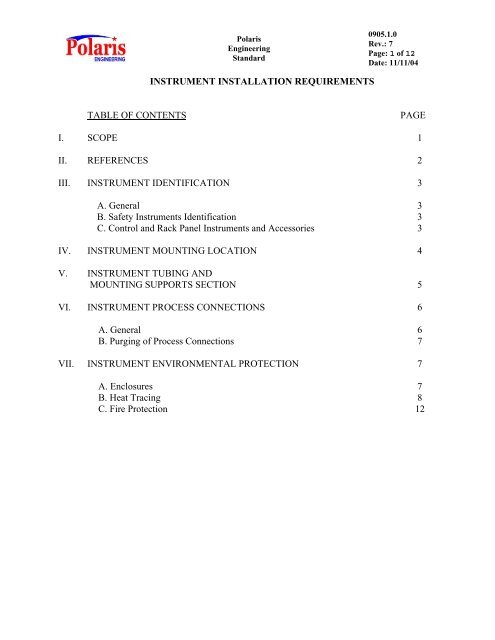
INSTRUMENT INSTALLATION REQUIREMENTS TABLE OF ...
INSTRUMENT INSTALLATION REQUIREMENTS TABLE OF ...
INSTRUMENT INSTALLATION REQUIREMENTS TABLE OF ...
You also want an ePaper? Increase the reach of your titles
YUMPU automatically turns print PDFs into web optimized ePapers that Google loves.
Polaris<br />
Engineering<br />
Standard<br />
0905.1.0<br />
Rev.: 7<br />
Page: 1 of 12<br />
Date: 11/11/04<br />
<strong>INSTRUMENT</strong> <strong>INSTALLATION</strong> <strong>REQUIREMENTS</strong><br />
<strong>TABLE</strong> <strong>OF</strong> CONTENTS<br />
PAGE<br />
I. SCOPE 1<br />
II. REFERENCES 2<br />
III. <strong>INSTRUMENT</strong> IDENTIFICATION 3<br />
A. General 3<br />
B. Safety Instruments Identification 3<br />
C. Control and Rack Panel Instruments and Accessories 3<br />
IV. <strong>INSTRUMENT</strong> MOUNTING LOCATION 4<br />
V. <strong>INSTRUMENT</strong> TUBING AND<br />
MOUNTING SUPPORTS SECTION 5<br />
VI. <strong>INSTRUMENT</strong> PROCESS CONNECTIONS 6<br />
A. General 6<br />
B. Purging of Process Connections 7<br />
VII. <strong>INSTRUMENT</strong> ENVIRONMENTAL PROTECTION 7<br />
A. Enclosures 7<br />
B. Heat Tracing 8<br />
C. Fire Protection 12<br />
911121<br />
d. Electric Heat Tracing 10<br />
e. Fire Protection 12
Polaris<br />
Engineering<br />
Standard<br />
0905.1.0<br />
Rev.: 7<br />
Page: 2 of 12<br />
Date: 11/11/04<br />
<strong>INSTRUMENT</strong> <strong>INSTALLATION</strong> <strong>REQUIREMENTS</strong><br />
I. SCOPE<br />
A. This Standard covers general requirements for installation of instruments and is<br />
intended to supplement specific job installation procedures and the Client and<br />
Polaris design drawings showing details of installations. Should conflict occur,<br />
specific job installation instructions along with the Client and Polaris design<br />
drawings shall govern.<br />
B. Where conflicts exist between this POLARIS Standard and other POLARIS<br />
Engineering Standards and/or applicable codes or regulations, the more stringent<br />
requirement shall govern. All conflicts shall be brought to the Client and<br />
Polaris’s attention for resolution. The Client and Polaris shall be the sole arbiter<br />
of any conflicts.<br />
C. No omission in these Standards shall be construed as relieving the Contractor of<br />
their responsibility to perform work in accordance with said codes and industry<br />
standards.<br />
II.<br />
REFERENCES<br />
This POLARIS Standard is to be used in conjunction with the latest revision of the<br />
standards and codes listed below, unless specifically noted. The terminology "latest<br />
revision" shall be interpreted as the revision in effect at the time of contract award. This<br />
POLARIS Standard may reference specific sections of some of these codes and<br />
standards. The revision of the codes and standards being referenced is noted below in<br />
parenthesis. This information is provided to identify the subject matter being referenced.<br />
Changes or exceptions made to the referenced code or standard shall apply to later<br />
revisions as applicable.<br />
A. POLARIS Engineering Standards:<br />
1. 190.1 General Plant Design Criteria<br />
2. 800.1 Piping – General Design<br />
3. 810.1 Heat Tracing<br />
4. 890.1 Piping Material Specifications<br />
5. 898.1 Piping General Notes And Details<br />
6. 898.14 Standard Steam Tracing Details<br />
7. 900.1 General Instrumentation Requirements
Polaris<br />
Engineering<br />
Standard<br />
0905.1.0<br />
Rev.: 7<br />
Page: 3 of 12<br />
Date: 11/11/04<br />
8. 905.2 Instrument Piping Materials<br />
9. 906.1 Instrument Piping Design, Layout and Drawing Procedures<br />
10. 920.1 Temperature Instruments<br />
11. 1000.1 Electrical - General Requirements<br />
12. 1073.1 Electric Heat Tracing<br />
B. Process Industry Practices (PIP) Standards:<br />
1. PIP PCCGN002 General Instrument Installation Criteria<br />
(October 2001)<br />
III.<br />
<strong>INSTRUMENT</strong> INDENTIFICATION<br />
A<br />
General<br />
1. All instruments, equipment, and enclosures shall be identified by the<br />
vendor before shipment by using at least one of the following methods:<br />
a. A permanently affixed nametag<br />
b. An engraving on the instrument<br />
c. A stainless steel tag affixed with a stainless steel wire<br />
2. Nameplates shall have, as a minimum, the device tag number engraved.<br />
3. The engineering contractor/designer shall include tagging requirements on<br />
instrument data sheets.<br />
4. All instrument tubing and wiring connections, including spares, shall be<br />
identified with permanent nametags, nameplates, or wire markers at tubing<br />
or wiring junctions. Paper nametags and hand written wire markers are<br />
not acceptable.<br />
B. Safety Instruments Identification<br />
1. See Engineering Standard 900.1 Section XI for details on identification of<br />
safety instruments.
Polaris<br />
Engineering<br />
Standard<br />
0905.1.0<br />
Rev.: 7<br />
Page: 4 of 12<br />
Date: 11/11/04<br />
C. Control and Rack Panel Instruments and Accessories<br />
1. Instruments and accessories that require identification nametags or<br />
nameplates shall include, as a minimum, the following:<br />
a. Control panel front-mounted instruments (complete nameplate on the<br />
front, nameplate or nametag with only the device number on the back)<br />
b. Control panel rear-mounted instruments<br />
c. Junction boxes, relay cabinets, and similar enclosures<br />
d. Control panel sections and racks<br />
e. Control system modular components (e.g., computers, programmable<br />
logic controllers, printers, I/O enclosures, racks, modules)<br />
f. Instrument electrical distribution equipment (e.g., fuses, breakers,<br />
switches)<br />
g. Control and indicating devices (e.g., hand switches, indication lights)<br />
2. Nameplates for recorders shall include a color-coded legend to designate<br />
the recorder pen color dedicated to the respective instrument tag number.<br />
IV.<br />
<strong>INSTRUMENT</strong> MOUNTING LOCATION<br />
A. Instrument mounting locations shall be selected with consideration of<br />
requirements for functional operation and maintenance.<br />
B. Field instruments shall be mounted to minimize the length of instrument impulse<br />
lines connected to process pipelines or equipment.<br />
C. All instruments that require calibration or maintenance shall be accessible from<br />
grade or from a permanent platform or ladder. These instruments shall be located<br />
between 2 and 5 feet above grade or platform. In flooding areas, these instruments<br />
shall be located at least 4 feet above ground. Safety/Emergency related<br />
instruments shall be accessible from grade or permanent platform.<br />
D. Instruments mounted outside a platform handrail shall be located to allow<br />
maintenance from the platform without reaching through or leaning over the<br />
hand rail. These instruments shall be located less than 5 feet above the platform<br />
and less than 1 foot horizontally outside the platform edge.<br />
E. Instruments shall be located no farther than 1.5 feet from fixed ladders to allow<br />
maintenance of the instrument from the ladder.<br />
F. Instruments including pressure gauges, dial thermometers, and gauge glasses shall<br />
be readable from grade, platforms, or permanent ladders.<br />
G. Instruments shall not protrude into or obstruct access ways so as to inhibit area<br />
personnel egress.
Polaris<br />
Engineering<br />
Standard<br />
0905.1.0<br />
Rev.: 7<br />
Page: 5 of 12<br />
Date: 11/11/04<br />
H. Instruments shall be located to allow performance of routine services with<br />
unobstructed access to the instrument.<br />
Comment:<br />
Clearances shall be provided for the removal of covers and<br />
cases and the opening of doors and enclosures. Access for<br />
appropriate lifting equipment shall be provided when<br />
necessary for control valves. Control valve bypass piping<br />
shall not interfere with mounting the control valve operator<br />
vertically.<br />
I. Local controllers and receiver instruments shall be located and readable in the<br />
vicinity of the final control element. Actions resulting from operational changes<br />
of a local instrument (e.g., control valve movement or vessel level changes) shall<br />
be observable from the receiver instrument location.<br />
V. <strong>INSTRUMENT</strong> AND TUBING MOUNTING SUPPORTS<br />
A. Direct-reading instruments shall be supported by piping or equipment. (e.g.,<br />
pressure gauges and dial thermometers).<br />
B. Field instruments shall be mounted on instrument supports designed for that<br />
purpose. Instruments shall not be supported from the process piping except for<br />
primary devices that must mount inline.<br />
Comment:<br />
Size and weight of instruments as well as heat or vibration<br />
in piping systems affect the mounting location and support<br />
requirements.<br />
C. A prefabricated, 2-inch, schedule 40 pipe stand support shall be used for field<br />
instrument mounting. The pipe stand shall be hot-dipped galvanized as a<br />
minimum requirement. The top of the pipe shall be plugged or sealed to prevent<br />
water entry.<br />
D. Welded areas, drilled holes, and pipe threads on galvanized steel shall be prepared<br />
and sprayed with cold galvanized coating.<br />
E. In general, single pipe stands dedicated to single instruments shall be used. When<br />
necessary, a single pipe stand fabricated to support multiple support arms may be<br />
used.<br />
F. Pipe stands shall be securely anchored. Where pipe stands are mounted to<br />
concrete surfaces, a 1” space between the mounting plate and grade shall be<br />
required to allow for grouting. Pipe stands directly embedded into concrete<br />
surfaces shall not be an acceptable practice.
Polaris<br />
Engineering<br />
Standard<br />
0905.1.0<br />
Rev.: 7<br />
Page: 6 of 12<br />
Date: 11/11/04<br />
G. Instrument process piping and tubing shall be supported as necessary to maintain<br />
structural integrity.<br />
H. All instrument piping and tubing between the instrument and process equipment<br />
or pipeline shall be properly supported to prevent strain on the instrument,<br />
equipment, and piping connections. Care shall also be taken to accommodate<br />
thermal expansion or relative motion of piping or equipment to which such<br />
instrument items are connected. Supporting instrument piping from bare hot or<br />
cold pipe shall be avoided.<br />
I. When fire protection is required for stainless steel tubing, it must be supported by<br />
stainless steel tray.<br />
VI. <strong>INSTRUMENT</strong> PROCESS CONNECTIONS<br />
A. General<br />
1. A line class root or isolation valve shall be provided at each process<br />
connection. This valve shall be specified and provided by the piping<br />
discipline.<br />
2. Instrument process connections shall be made to either the side, top, or<br />
upper or lower 45-degree angle of process piping or equipment as directed<br />
by the Client and Polaris. When low-side connections are specified, these<br />
connections shall be sufficiently high to prevent plugging by dirt or<br />
suspended solids.<br />
Connections shall be short and without pockets.<br />
3. Special attention shall be given to the location of process connections on<br />
vessels. Temperature sensors shall be placed in flowing streams, not in<br />
stagnant fluid. Where equipment has piped bypass, temperature sensors<br />
shall be installed outside the bypass piping.<br />
4. Pressure-sensing points (for pressure, differential, and level<br />
measurements) shall be located such that error from fluid impact and<br />
velocity effects is avoided.<br />
5. Instrument process connections shall conform to the requirements in the<br />
piping or equipment specifications.<br />
B. Purging of Process Connections<br />
1. Purging of process connections shall be used to prevent plugging, freezing<br />
and corroding.<br />
2. The purge fluid shall be compatible with the process fluid.
Polaris<br />
Engineering<br />
Standard<br />
0905.1.0<br />
Rev.: 7<br />
Page: 7 of 12<br />
Date: 11/11/04<br />
3. When purging is required, the purging system shall not induce error in the<br />
process measurement.<br />
4. Gas purges shall not exceed 3 standard cubic feet per hour, and liquid<br />
purges shall not exceed 3 gallons per hour, unless specifically required by<br />
design conditions.<br />
5. Gas purges shall be traced and insulated if condensation is a problem.<br />
6. Provision shall be made for draining condensed liquids from gas purge<br />
systems at low points in the piping system.<br />
7. For solids-bearing streams, the purge instrument connections to the<br />
process equipment or piping shall be vertical or angled up.<br />
8. Purge should be near the process connection. The purge may be located<br />
nearer to the instrument when impulse tubing lines are long.<br />
9. The temperature of the purge fluid shall not cause a change of state<br />
(flashing, condensation, or solidification) of the process or purge fluid.<br />
10. The supply source of the purge fluid shall be independent from the process<br />
fluid so that it is available even when the process is not operating<br />
normally.<br />
11. The purge fluid flow rate shall be the same to each tap on an orifice meter<br />
installation.<br />
12. Purging systems shall include a check valve and shutoff valve.<br />
VII.<br />
<strong>INSTRUMENT</strong> ENVIRONMENTAL PROTECTION<br />
A. Enclosures<br />
1. Instruments requiring protection from freezing shall be provided with an<br />
insulating protective enclosure. Manifold valves, where required, shall be<br />
included within the enclosure.<br />
2. The temperature for instrument electronics shall be maintained within the<br />
manufacturer’s recommended minimum and maximum values.<br />
3. Use of “soft” type instrument enclosures is acceptable where space<br />
requirements are not adequate for hard-pack enclosures.<br />
4. Electrical heating elements used in the enclosure shall meet the electrical
Polaris<br />
Engineering<br />
Standard<br />
0905.1.0<br />
Rev.: 7<br />
Page: 8 of 12<br />
Date: 11/11/04<br />
area classification.<br />
5. Space inside an enclosure and around the instrument shall be adequate for<br />
routine maintenance and for removal of the instrument. Properly sized and<br />
positioned access doors are required.<br />
6. Process impulse lines shall enter through the side or bottom of the<br />
enclosure (never through the top) and shall be located to minimize piping<br />
requirements. All penetrations through the side or bottom shall be sealed.<br />
7. Full hard-pack enclosures shall be wall-mounted or attached to an<br />
instrument pipe stand.<br />
8. Metal enclosures shall be corrosion resistant. The hardware, assembly<br />
bolts, and screws shall be stainless steel. NEMA 4X enclosures shall be<br />
the minimum rating for outdoor instrumentation.<br />
B. Heat Tracing<br />
1. General<br />
2. Steam Tracing<br />
a. Process impulse lines and instruments containing either<br />
vapors that may condense at ambient temperatures or<br />
liquids that will freeze or congeal shall be insulated and/or<br />
heat traced. Each potential application shall be investigated<br />
to determine the degree and type of heat tracing that is<br />
required. This section does not cover heat tracing for<br />
process pipelines.<br />
b. Self-limiting electric tracing shall not be used when<br />
temperatures exceed 250°F.<br />
c. Steam tracing can be used when required system<br />
temperatures are above 200°F.<br />
d. Constant-resistance electric tracing shall be used when<br />
temperature control is required.<br />
e. Insulation and heat tracing shall be applied to the processwetted<br />
parts of the instrument, never to electronics or to<br />
pneumatic parts.<br />
a. The use of prefabricated heat-tracing bundles is preferred.<br />
When short leads or configuration prevents reasonable use
Polaris<br />
Engineering<br />
Standard<br />
0905.1.0<br />
Rev.: 7<br />
Page: 9 of 12<br />
Date: 11/11/04<br />
of this material, individually designed systems shall be<br />
provided. See POLARIS Standard 810.1 for (steam) Heat<br />
Tracing.<br />
b. For maximum heat transfer, the tracer shall be held in<br />
direct contact with the instrument line or equipment. Steam<br />
pressure shall be selected for the desired heating; however,<br />
consideration must be given to boiling or process<br />
degradation.<br />
c. When the process fluid in the instrument line is temperature<br />
sensitive or has a boiling point lower than the steam<br />
temperature, the tracer shall be separated from the line<br />
using a spacer or insulation to prevent hot spots in the<br />
heated line. Asbestos-free insulation tape or blocks shall be<br />
used to separate steam tracing tubing from meter body,<br />
instrument enclosure, and impulse tubing and piping.<br />
Spacing shall be a minimum of 1/2 inch.<br />
d. All steam tracing connections shall be made outside the<br />
instrument enclosure.<br />
e. Low-pressure steam (less than 75 pounds per square inch<br />
gage [psig]) shall be used for steam tracing of impulse<br />
lines.<br />
f. Pre-insulated tubing shall be used to carry steam tracing<br />
from a steam<br />
tracing station to the instrument to be traced.<br />
g. If a condensate return system is available condensate from<br />
individual steam traps shall be returned by pre-insulated<br />
tubing.<br />
h. Instrument tracing tubing shall be 3/8-inch or ½- inch<br />
outside diameter (OD) 316SS x 0.035 inch wall.<br />
i. The steam supply to the tracing leads shall enter at the high<br />
point of the tracing system. The tracing leads shall be<br />
horizontal or continuously sloped downward to a steam<br />
trap, low-point drain, or condensate return header.<br />
j. A separate trap shall be installed for each tracer circuit.<br />
k..<br />
All bare steam tracers shall be insulated for protection of<br />
personnel.
Polaris<br />
Engineering<br />
Standard<br />
0905.1.0<br />
Rev.: 7<br />
Page: 10 of 12<br />
Date: 11/11/04<br />
l. Ends of tubing bundles and any other openings shall be<br />
sealed to prevent entrance of moisture.<br />
m. Tracing of individual instruments shall be done to allow<br />
removal of the instrument for maintenance.<br />
Comment:<br />
To prevent removal of the tracing line to an<br />
instrument, a tubing block valve may be<br />
installed in the racer line at each instrument.<br />
This installation avoids closing the header<br />
valve for maintenance. A valve is also<br />
required on the condensate return line if the<br />
condensate discharges to a header. Tubing<br />
unions shall be supplied on both ends of<br />
tracing wrap for the instrument. Unions<br />
installed in tracer systems shall be left uninsulated<br />
for easy access, unless protection<br />
is required.<br />
3. Electric Heat Tracing<br />
n. Steam branches shall be taken from the top of the header to<br />
assure that dry steam will be supplied. Each branch shall<br />
have an individual shutoff valve to eliminate bypassing and<br />
recycling within the tracer system. Each tracer shall be<br />
individually trapped.<br />
o. Traps shall be accessible for inspection and maintenance.<br />
p. Siphons, flanges, etc., are to be wrapped completely with<br />
fiberglass tape to enclose tracer and instrument piping,<br />
even though the tracer may not follow the siphon or fullflange<br />
surface.<br />
q. Condensate pots shall not be insulated.<br />
a. Electric heat tracing shall only be used in the absence of<br />
steam, other economic considerations, or other technical<br />
reasons deem it advisable. Use of electric tracing requires<br />
the Client and Polaris’s approval. See POLARIS Standard<br />
1073.1 for Electrical Heat Tracing. Wind velocity of 25<br />
miles per hour (mph) shall be used in determining the<br />
required heat input. The system shall be designed to<br />
maintain the temperature of all freeze-protected lines<br />
and/or instruments at 50°F or greater, as required. In
Polaris<br />
Engineering<br />
Standard<br />
0905.1.0<br />
Rev.: 7<br />
Page: 11 of 12<br />
Date: 11/11/04<br />
addition, an energy disconnect device must be provided for<br />
each electric traced instrument.<br />
b. When designing an electric tracing system, abnormal<br />
situations such as steam outs shall be considered. The heat<br />
tracing cable shall be designed to withstand the maximum<br />
steam out temperature.<br />
c. Electric heat tracing shall be designed to meet the electrical<br />
area classification of the area in which the tracing will be<br />
installed Components used in the system shall be approved<br />
by nationally recognized laboratory for the area<br />
classification involved.<br />
d. Self-limiting parallel resistance or constant-watt parallel<br />
resistance type heating cable shall be used for electric heat<br />
tracing. Heating cables shall be selected with a watts per<br />
foot rating to prevent overheating.<br />
e. Only mineral-insulated or high-temperature-rated constantwatt-type<br />
heating cable shall be used.<br />
f. Prefabricated tubing bundle systems (consisting of process<br />
compatible instrument tubing, self-limiting or constant-watt<br />
heater cables with insulation, and outer jacket) shall be the<br />
preferred method of freeze protecting and heat tracing<br />
instrument impulse lines.<br />
g. Each heat tracing cable shall be permanently tagged with a<br />
stainless steel identification tag attached at the power<br />
connection box end of the circuit. The tag for each cable<br />
shall indicate the panel identification (ID) and circuit<br />
number.<br />
h. Heat trace cables shall be installed according to the<br />
manufacturer’s recommended standards. Detail drawings<br />
shall give information concerning specific application to<br />
instrumentation and impulse lines. The manufacturer’s<br />
installation procedures shall be followed.
Polaris<br />
Engineering<br />
Standard<br />
0905.1.0<br />
Rev.: 7<br />
Page: 12 of 12<br />
Date: 11/11/04<br />
i. Tracing of individual instruments shall be done to allow<br />
removal of the instrument for maintenance.<br />
Comment:<br />
A breaker panel may be provided to deenergize<br />
circuits, or physical disconnects<br />
may be provided in tracers to permit the<br />
removal of instruments without distorting or<br />
cutting the wire.<br />
j. All electrically traced instruments shall be properly tagged<br />
with a warning about the danger of cutting into an<br />
energized cable when removing insulation.<br />
C. Fire Protection<br />
1. Instrumentation systems shall be provided with protection from an<br />
external fire when specified in Engineering Standard 1300.1<br />
Protection shall be provided for instrument components, tubing,<br />
wiring, conduit, and control valves.<br />
2. Fire protection shall be specific to the type of hazard and can be<br />
achieved by using intumescent coating, insulation, jacketing, deluge,<br />
or a combination of methods.


