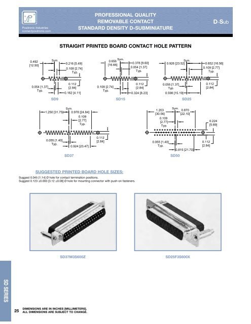
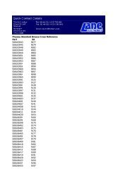
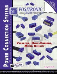
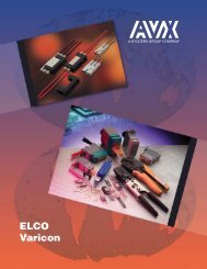
<strong>Positronic</strong> <strong>Industries</strong> connectpositronic.com PROFESSIONAL QUALITY REMOVABLE CONTACT STANDARD DENSITY D-SUBMINIATURE D-Sub STRAIGHT PRINTED BOARD CONTACT HOLE PATTERN 0.492 [12.50] Sym. Sym. 0.656 0.216 [5.49] [16.66] 0.108 [2.74] Typ. 0.378 [9.60] 0.054 [1.37] Typ. Sym. 0.926 [23.52] 0.652 [16.56] 0.109 [2.77] Typ. 0.054 [1.37] Typ. 0.112 [2.84] 0.162 [4.11] 0.108 [2.74] Typ. 0.112 [2.84] 0.324 [8.23] 0.055 [1.37] Typ. 0.598 [15.19] SD9 SD15 SD25 0.112 [2.84] Sym. 1.250 [31.75] 0.978 [24.84] 0.109 [2.77] Typ. 1.203 [30.56] 0.109 [2.77] Typ. Sym. 0.870 [22.10] 0.224 [5.69] 0.055 [1.40] Typ. 0.924 [23.47] 0.112 [2.84] 0.055 [1.40] Typ. 0.815 [21.70] 0.112 [2.84] SD37 SD50 SUGGESTED PRINTED BOARD HOLE SIZES: Suggest 0.045 [1.14] Ø hole for contact termination positions. Suggest 0.123 ±0.003 [3.12 ±0.08] Ø hole for mounting connector with push-on fasteners. SD37M3S600Z SD25F3S600X SD SERIES 25 DIMENSIONS ARE IN INCHES [MILLIMETERS]. ALL DIMENSIONS ARE SUBJECT TO CHANGE.
P O S I T R O N I C I N D U S T R I E S D-Sub PROFESSIONAL QUALITY REMOVABLE CONTACT STANDARD DENSITY D-SUBMINIATURE <strong>Positronic</strong> <strong>Industries</strong> connectpositronic.com ORDERING INFORMATION - CODE NUMBERING SYSTEM Specify Complete Connector By Selecting An Option From Step 1 Through 8 STEP EXAMPLE 1 2 3 4 5 6 7 8 9 SD 15 F 0 0 0 0 X /AA 10 -14 STEP 1 - BASIC SERIES SD series. STEP 2 - CONNECTOR VARIANTS 9, 15, 25, 37, 50 STEP 3 - CONNECTOR GENDER M - Male F - Female STEP 4 - CONTACT TERMINATION TYPE 0 - Contacts ordered separately, see page 23. 1 - Crimp, 20 AWG-24 AWG [0.5mm 2 -0.25mm 2 ]. 12 - Crimp, 26 AWG-30 AWG [0.12mm 2 -0.05mm 2 ]. 3 - Solder, Straight Printed Board Mount with 0.125 [3.18] Tail Length. 32 - Solder, Straight Printed Board Mount with 0.188 [4.78] Tail Length. * 1 STEP 5 - MOUNTING STYLE 0 - Mounting Hole, 0.120 [3.05] Ø. 02 - Mounting Hole, 0.154 [3.91] Ø. F - Float Mounts, Universal. P - Threaded Post, Brass, 0.437 [11.10] Length. P2 - Threaded Post, Nylon, 0.437 [11.10] Length. S - Swaged Spacer, 4-40 Threads, 0.437 [11.10] Length. S2 - Swaged Spacer, 4-40 Threads, 0.125 [3.18] Length. S5 - Swaged Locknut, 4-40 Threads. S6 - Swaged Spacer with Push-on Fastener, 4-40 Threads, 0.437 [11.10] Length. * 1 STEP 6 - HOODS 0 - None. J - Hood, Top Opening, Plastic. L - Hood, Side Opening, Plastic. Y - Hood, Top Opening, Plastic with Rotating Male Jackscrews. Available in size 50 only. Y6 - Hood, Top Opening, Plastic with Rotating Male and Female Polarized Jackscrews. Available in size 50 only. Z - Hood, Top or Side Opening, Robust and Extended Height, Composite and Plastic with Rotating Male Jackscrews. H - Hood, Top Opening, Metal. Available in size 15, 25, 37, and 50 only. G - Hood, EMI/RFI, Die Cast Zinc. AN - Lightweight Aluminum Hood, nickel finish. AC - Lightweight Aluminum Hood, no finish. W - Hood, Top or Side Opening, Plastic. Available in size 9,15, and 25 only. RoHS Compliant • per EU Directive 2002/95/EC • STEP 10 - SPECIAL OPTIONS -14 - 0.000030 [0.76µ] gold over nickel. -15 - 0.000050 [1.27µ] gold over nickel. CONTACT TECHNICAL SALES FOR SPECIAL OPTIONS STEP 9 - ENVIRONMENTAL COMPLIANCE OPTIONS /AA - Compliant per EU Directive 2002/95/EC (RoHS) NOTE: If compliance to environmental legislation is not required, this step will not be used. Example: SD15F0000X STEP 8 - Shell Options 0 - Zinc Plated, with Chromate Seal. * 3 S - Stainless steel, passivated. X - Tin Plated. Z - Tin Plated and Dimpled (male connectors only). * 1 STEP 7 - LOCKING AND POLARIZING SYSTEMS 0 - None. * 2 V3- Lock Tab, connector front panel mounted. * 2 V5- Lock Tab, connector rear panel mounted. * 2 VL - Lock Lever, used with Hoods Only. T - Fixed Female Jackscrews. T2 - Fixed Female Jackscrews. T6 - Fixed Male and Female Polarized Jackscrews. E - Rotating Male Jackscrews. E2 - Rotating Male Screw Locks. E3 - Rotating Male with internal hex for 3/32 hex drives E6 - Rotating Male and Female Polarized Jackscrews. NOTE: Once you have made a connector selection, contact Technical Sales if you would like to receive a drawing in DXF, PDF format or a 3-dimensional IGES, STEP, or SOLIDWORKS file. * 1 For additional information on accessories listed in steps 5, 6 and 7, see Accessory <strong>Catalog</strong>. * 2 VL, V3 and V5 locking systems are not available for connector variants 37 and 50. Jackscrews are highly recommended to minimize damage to contacts on variants with high mating forces. * 3 For stainless steel dimpled male versions contact Technical Sales. For information regarding CRIMP TOOLS & CRIMPING TOOL TECHNIQUES, see page 78. 2-D Drawing 3-D Model DIMENSIONS ARE IN INCHES [MILLIMETERS]. ALL DIMENSIONS ARE SUBJECT TO CHANGE. 26 SD SERIES