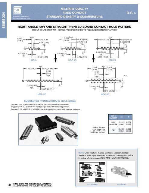
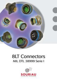
HDC SERIES <strong>Positronic</strong> <strong>Industries</strong> connectpositronic.com MILITARY QUALITY FIXED CONTACT STANDARD DENSITY D-SUBMINIATURE RIGHT ANGLE (90°) AND STRAIGHT PRINTED BOARD CONTACT HOLE PATTERN MOUNT CONNECTOR WITH MATING FACE POSITIONED TO FOLLOW DIRECTION OF ARROW. D-Sub 0.492 [12.50] Sym. Sym. 0.656 0.216 [5.49] [16.66] 0.108 [2.74] Typ. 0.378 [9.60] 0.054 [1.37] Typ. Sym. 0.926 [23.52] 0.652 [16.56] 0.109 [2.77] Typ. 0.054 [1.37] Typ. X 0.108 [2.74] X 0.055 [1.40] X Typ. Typ. 0.162 [4.11] 0.324 [8.23] 0.598 [15.19] HDC 9 HDC 15 HDC 25 Sym. 1.250 [31.75] 0.978 [24.84] 0.109 [2.77] Typ. 1.203 [30.56] 0.109 [2.77] Typ. Sym. 0.870 [22.10] Y 0.055 [1.40] Typ. 0.924 [23.47] X 0.055 [1.40] Typ. 0.815 [20.70] X HDC 37 HDC 50 SUGGESTED PRINTED BOARD HOLE SIZES: Suggest 0.039 [0.99] Ø hole for 0.024 [0.61] Ø contact termination positions. Suggest 0.045 [1.14] Ø hole for 0.028 [0.71] Ø contact termination positions. Suggest 0.123 ±0.003 [3.12 ±0.08] Ø hole for mounting connector with push-on fasteners. CODE NUMBER X Y 3, 5, 32, 33, 36 0.112 [2.84] 0.224 [5.69] *Metric system, European contact hole pattern. *42 0.100 [2.54] 0.200 [5.08] NOTE: Once you have made a connector selection, contact Technical Sales if you would like to receive a drawing in DXF, PDF format or a 3-dimensional IGES, STEP, or SOLIDWORKS file. 31 DIMENSIONS ARE IN INCHES [MILLIMETERS]. ALL DIMENSIONS ARE SUBJECT TO CHANGE. 2-D Drawing 3-D Model
P O S I T R O N I C I N D U S T R I E S D-Sub MILITARY QUALITY FIXED CONTACT STANDARD DENSITY D-SUBMINIATURE ORDERING INFORMATION - CODE NUMBERING SYSTEM Specify Complete Connector By Selecting An Option From Step 1 Through 8 <strong>Positronic</strong> <strong>Industries</strong> connectpositronic.com HDC SERIES STEP EXAMPLE 1 2 3 4 5 6 7 8 9 HDC 37 S 5 B3 0 T 0 /AA 10 -50 STEP 1 - BASIC SERIES HDC series. STEP 2 - CONNECTOR VARIANTS 9, 15, 25, 37, 50 STEP 3 - CONNECTOR GENDER M - Male S - Female - PosiBand closed entry contacts STEP 4 - CONTACT TERMINATION TYPE 2 - Solder cup. 3 - Solder, Straight Printed Board Mount with 0.170 [4.32] Tail Length. 32 - Solder, Straight Printed Board Mount with 0.375 [9.52] Tail Length. 33 - Solder, Straight Printed Board Mount with 0.500 [12.70] tail length. 36 - Solder, Straight Printed Board Mount with 0.236 [5.99] Tail Length. 42 - Solder, Metric System Right Angle (90°) Printed Board Mount with 0.370 [9.40] Contact Extension. 5 - Solder, Right Angle (90°) Printed Board Mount with 0.283 [7.19] Contact Extension. 6 - Wrap Post. * 1 STEP 5 - MOUNTING STYLE 0 - Mounting Hole, 0.120 [3.05] Ø. 02 - Mounting Hole, 0.154 [3.91] Ø. B3 - Bracket, Mounting, Right Angle (90°) Metal with Cross Bar. B8 - Bracket, Mounting, Right Angle (90°) Plastic with Cross Bar. F - Float Mounts, Universal. P - Threaded Post, Brass, 0.225 [5.71] Length. P2 - Threaded Post, Nylon, 0.225 [5.71] Length. R2 - Bracket, Mounting, Right Angle (90°) Metal, Swaged to Connector with 4-40 Thread Fixed Female Jackscrews with Cross Bar. R6 - Bracket, Mounting, Right Angle (90°) Metal, Swaged to Connector with 0.120 [3.05] Ø Mounting Hole with Cross Bar. R7 - Bracket, Mounting, Right Angle (90°) Metal, Swaged to Connector with 4-40 Threads with Cross Bar. R8 - Bracket, Mounting, Right Angle (90°) Metal, Swaged to Connector with 4-40 Locknut with Cross Bar. S - Swaged Spacer, 4-40 Threads, 0.225 [5.71] Length. S2 - Swaged Spacer, 4-40 Threads, 0.125 [3.18] Length. S5 - Swaged Locknut, 4-40 Threads. S6 - Swaged Spacer with Push-on Fastener, 4-40 Threads, 0.225 [5.71] Length. S7 - Swaged Spacer with Push-on Fastener for use with Ferrite Inductor, 4-40 Threads, 0.375 [9.53] Length. * 1 For additional information on accessories listed in steps 5, 6 and 7, see Accessory <strong>Catalog</strong>. * 2 Ferrite inductor is available on contact types 32, 33, 36 and 6 only. For more information on ferrite inductors, see page 7. * 3 For stainless steel dimpled male versions contact Technical Sales. RoHS Compliant • per EU Directive 2002/95/EC • STEP 10 - SPECIAL OPTIONS -14 - 0.000030 [0.76µ] gold over nickel. -15 - 0.000050 [1.27µ] gold over nickel. -50 - 0.000050 [1.27µ] gold over copper. CONTACT TECHNICAL SALES FOR ORDERING DETAILS OF THE FOLLOWING: Other Special Requirements. Straight and Right Angle (90°) Thermocouple printed circuit board mount contacts STEP 9 - ENVIRONMENTAL COMPLIANCE OPTIONS /AA - Compliant per EU Directive 2002/95/EC (RoHS) NOTE: If compliance to environmental legislation is not required, this step will not be used. Example: HDC37S5B30T0 STEP 8 -SHELL OPTIONS 0 - Zinc Plated with Chromate Seal. * 3 S - Stainless steel, passivated. X - Tin Plated. Z - Tin Plated and Dimpled (male connectors only). C - Cadmium plated with Chromate Seal * 1 STEP 7 -LOCKING AND POLARIZING SYSTEMS 0 - None. V3 - Lock Tab, connector front panel mounted. V5 - Lock Tab, connector rear panel mounted. VL - Lock Lever, used with Hoods Only. T - Fixed Female Jackscrews. T2 - Fixed Female Jackscrews. T6 - Fixed Male and Female Polarized Jackscrews. E - Rotating Male Jackscrews. E2 - Rotating Male Screw Locks. E3 - Rotating Male with internal hex for 3/32 hex drives E6 - Rotating Male and Female Polarized Jackscrews. * 1 STEP 6 - HOODS AND PUSH-ON FASTENERS 0 - None. J - Hood, Top Opening, Plastic. L - Hood, Side Opening, Plastic. Y - Hood, Top Opening, Plastic with Rotating Male Jackscrews. Available in size 50 only. Y6 - Hood, Top Opening, Plastic with Rotating Male and Female Polarized Jackscrews. Available in size 50 only. Z - Hood, Top or Side Opening, Robust and Extended Height, Composite and Plastic with Rotating Male Jackscrews. H - Hood, Top Opening, Metal. Available in size 15, 25, 37 and 50 only. G - Hood, EMI/RFI, Die Cast Zinc. AN - Lightweight Aluminum Hood, nickel finish. AC - Lightweight Aluminum Hood, no finish. W - Hood, Top or Side Opening, Plastic. Available is size 9, 15, and 25 only. N - Push-on Fastener, for Right Angle (90°) Mounting Brackets. * 2 F - Ferrite Inductor. DIMENSIONS ARE IN INCHES [MILLIMETERS]. ALL DIMENSIONS ARE SUBJECT TO CHANGE. 32