Specification for Timber Frame Construction
Specification for Timber Frame Construction
Specification for Timber Frame Construction

Create successful ePaper yourself
Turn your PDF publications into a flip-book with our unique Google optimized e-Paper software.
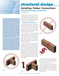
= breadth of rectangular bending member, in.<br />
d = depth of bending member or least dimension of rectangular compression member, in.<br />
d n = depth of member remaining at a notch, in., see 2.3.3<br />
l e = end distance, in., see 3.1.1.2<br />
l m = dowel bearing length in the main member, or tenon breadth, in., see3.4.1<br />
l s = dowel bearing length in the side member, or minimum mortise side wall thickness on<br />
one side of tenon, in., see 3.4.1<br />
l v = edge distance, in., see 3.1.1.1<br />
w 1 , w 2 , w 3 = width of partial-width notch, in., see 2.3.4<br />
w m = width of mortise, see 3.4.11<br />
w s = width of side wall on either side of mortise, see 3.4.11<br />
θ = maximum angle of load to grain <strong>for</strong> any member in a connection, deg, see 3.4.1<br />
TFEC 1-2010 Standard Page 9 June 2010