Specification for Timber Frame Construction
Specification for Timber Frame Construction
Specification for Timber Frame Construction

You also want an ePaper? Increase the reach of your titles
YUMPU automatically turns print PDFs into web optimized ePapers that Google loves.
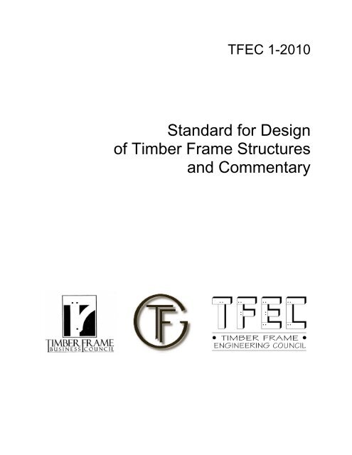
TFEC 1-2010<br />
Standard <strong>for</strong> Design<br />
of <strong>Timber</strong> <strong>Frame</strong> Structures<br />
and Commentary
TFEC 1-2010<br />
Standard <strong>for</strong> Design<br />
of <strong>Timber</strong> <strong>Frame</strong> Structures<br />
and Commentary<br />
<strong>Timber</strong> <strong>Frame</strong> Engineering Council<br />
Technical Activities Committee (TFEC-TAC)<br />
Tom Nehil – Co-Chairman<br />
Ben Brungraber<br />
Ed Levin<br />
Jim DeStefano – Co-Chairman<br />
Joe Miller<br />
Dick Schmidt<br />
Funding <strong>for</strong> development of this standard was provided by the <strong>Timber</strong> <strong>Frame</strong>rs Guild and<br />
the <strong>Timber</strong> <strong>Frame</strong> Business Council<br />
Copyright © 2010<br />
<strong>Timber</strong> <strong>Frame</strong> Engineering Council<br />
PO Box 60<br />
Becket, MA 01223<br />
TFEC 1-2010 Standard Page 1 June 2010
Standard <strong>for</strong> Design of <strong>Timber</strong> <strong>Frame</strong> Structures .................................................................... 3<br />
1.0 General Requirements <strong>for</strong> Structural Design and <strong>Construction</strong> ....................................... 3<br />
1.1 Applicability and Scope................................................................................................ 3<br />
1.2 Liability ........................................................................................................................ 3<br />
1.3 General Requirements .................................................................................................. 4<br />
1.4 Design Loads ................................................................................................................ 5<br />
1.5 <strong>Construction</strong> Documents .............................................................................................. 5<br />
1.6 Materials ....................................................................................................................... 6<br />
1.7 Notation ........................................................................................................................ 8<br />
2.0 Structural Members ........................................................................................................ 10<br />
2.1 General........................................................................................................................ 10<br />
2.2 Seasoning Effects ....................................................................................................... 10<br />
2.3 Notching ..................................................................................................................... 10<br />
3.0 Connections .................................................................................................................... 13<br />
3.1 General........................................................................................................................ 13<br />
3.2 Withdrawal ................................................................................................................. 15<br />
3.3 Mortise and Tenon Connections Loaded in Shear ...................................................... 15<br />
3.4 Mortise and Tenon Connections Loaded in Tension .................................................. 16<br />
3.5 Seasoning Effects ....................................................................................................... 24<br />
4.0 Design <strong>for</strong> Lateral Loads ................................................................................................ 25<br />
4.1 Stand-Alone <strong>Timber</strong> <strong>Frame</strong>s ...................................................................................... 25<br />
4.2 <strong>Timber</strong> <strong>Frame</strong>s and Diaphragm - Shear Wall Systems .............................................. 25<br />
Appendix A – Glossary ............................................................................................................. 27<br />
Appendix B – References ......................................................................................................... 30<br />
TFEC 1-2010 Standard Page 2 June 2010
Standard <strong>for</strong> Design of <strong>Timber</strong> <strong>Frame</strong> Structures<br />
1.0 General Requirements <strong>for</strong> Structural Design and <strong>Construction</strong><br />
1.1 Applicability and Scope<br />
This Standard defines the engineering and design requirements <strong>for</strong> timber frame construction. A<br />
timber frame shall be regarded as a structural building frame system or a portion thereof that is<br />
composed of timber members in which connections between interlocking members are created<br />
by carpenter-style joinery using wood pegs and wood wedges.<br />
This Standard is not intended to preclude use of other materials, assemblies, structures or designs<br />
not meeting the criteria herein, provided it is demonstrated by analysis based on recognized<br />
theory, full scale or prototype loading tests, studies of model analogues or extensive experience<br />
in use that the material, assembly, structure or design will per<strong>for</strong>m satisfactorily in its intended<br />
end use.<br />
This Standard is intended as a supplement to provisions of the National Design <strong>Specification</strong> <strong>for</strong><br />
Wood <strong>Construction</strong> (ANSI/AF&PA NDS © , Reference 1). In the event of conflicts or<br />
contradictory requirements between this Standard and the NDS © , the provisions of the latter<br />
specification shall apply.<br />
1.2 Liability<br />
It is intended that this document be used in conjunction with competent engineering design,<br />
accurate fabrication, and adequate supervision of construction. The <strong>Timber</strong> <strong>Frame</strong> Business<br />
Council and the <strong>Timber</strong> <strong>Frame</strong>rs Guild do not assume any responsibility <strong>for</strong> errors or omissions<br />
in this document, nor <strong>for</strong> engineering designs, plans, or construction prepared from it. Those<br />
TFEC 1-2010 Standard Page 3 June 2010
using this Standard assume all liability arising from its use. The design of engineered structures<br />
is within the scope of expertise of licensed engineers, architects, or other licensed professionals<br />
<strong>for</strong> applications to a particular structure.<br />
1.3 General Requirements<br />
1.3.1 Strength<br />
Buildings and other structures shall be designed and constructed to safely support the anticipated<br />
loads that are likely to occur during the lifetime of the structure. In addition, assemblies and<br />
subassemblies shall be designed and constructed to safely support those loads that are likely to<br />
occur during construction, including but not limited to frame assembly and raising. Load types,<br />
magnitudes, and combinations shall con<strong>for</strong>m to the building code under which the structure is<br />
designed, or where applicable, other recognized minimum design-load standards (see References<br />
4 and 6).<br />
1.3.2 Serviceability<br />
Structural systems and members thereof shall be designed to have adequate stiffness to limit<br />
deflections, lateral drift, vibration, or any other de<strong>for</strong>mations that adversely affect the intended<br />
use and per<strong>for</strong>mance of the system. Limitations on deflections, lateral drift, vibration, and other<br />
de<strong>for</strong>mations shall con<strong>for</strong>m to the provisions of the building code under which the structure is<br />
designed.<br />
1.3.3 General Structural Integrity<br />
Buildings and other structures shall be designed to sustain local damage with the structural<br />
system as a whole remaining stable and not damaged to an extent disproportional to the original<br />
TFEC 1-2010 Standard Page 4 June 2010
damage location. This shall be accomplished by providing sufficient continuity, redundancy, or<br />
energy-dissipating capacity (ductility), or a combination thereof, in the members of the structure.<br />
1.3.4 Con<strong>for</strong>mance with Standards<br />
The quality of wood products and fasteners and the design of load-supporting members and<br />
connections shall con<strong>for</strong>m to the standards specified herein.<br />
1.4 Design Loads<br />
1.4.1 Governed by Codes<br />
Minimum design loads shall be in accordance with the local building code under which the<br />
structure is designed. In the absence of a local building code, the minimum design loads<br />
specified in Minimum Design Loads <strong>for</strong> Buildings and Other Structures (SEI/ASCE 7; see<br />
Reference 4) shall be used.<br />
1.4.2 Loads Included<br />
Where applicable, design loads shall include any or all of the following loads or <strong>for</strong>ces: dead,<br />
live, snow, wind, earthquake, erection and other static and dynamic <strong>for</strong>ces.<br />
1.5 <strong>Construction</strong> Documents<br />
1.5.1 Types of Documents<br />
<strong>Construction</strong> documents shall be understood to include contracts, plans, specifications, shop<br />
drawings and other documents as agreed by the contracting parties intended to convey the<br />
construction requirements <strong>for</strong> the structure.<br />
TFEC 1-2010 Standard Page 5 June 2010
1.5.2 Material Selection<br />
The construction documents shall indicate the species or species group of the timber as well as<br />
the stress grade and grading rules <strong>for</strong> each structural load-carrying member used in construction.<br />
The construction documents shall also indicate the species and minimum density of wood used<br />
<strong>for</strong> design of pegs and wedges in the structure.<br />
1.5.3 Member Sizes<br />
The construction documents shall indicate whether timber member sizes are stated in terms of<br />
standard nominal dimensions, standard net dimensions, or other designations.<br />
1.5.4 Connection Details<br />
The construction documents shall indicate the dimensions necessary <strong>for</strong> connection fabrication.<br />
Locations and sizes of tenons, mortises, housings, and other connection components shall be<br />
specified such that fabrication quality can be evaluated.<br />
1.6 Materials<br />
1.6.1 Sawn <strong>Timber</strong><br />
Design values <strong>for</strong> solid-sawn timbers used as structural load-carrying members shall be as<br />
specified <strong>for</strong> the species groups and grades defined in the National Design <strong>Specification</strong> <strong>for</strong><br />
Wood <strong>Construction</strong> Supplement, Design Values <strong>for</strong> Wood <strong>Construction</strong>. Lumber shall be<br />
identified by the grade mark of, or certificate of inspection issued by, a certified grader, a lumber<br />
grading or inspection bureau, or an agency recognized by the American Lumber Standards<br />
Committee.<br />
TFEC 1-2010 Standard Page 6 June 2010
1.6.2 Structural Glued Laminated <strong>Timber</strong><br />
Design values <strong>for</strong> structural glued laminated timber (glulam) shall be as specified <strong>for</strong> the<br />
laminating combination as listed in the NDS ® Supplement, American Institute of <strong>Timber</strong><br />
<strong>Construction</strong> (AITC) Standard <strong>Specification</strong> AITC 117, or AITC 119 (see References 7 and 8).<br />
Glulam shall bear a quality mark from an accredited inspection agency certifying con<strong>for</strong>mance<br />
with ANSI/AITC A190.1 (see Reference 9). Where significant amounts of the cross section will<br />
be removed to accommodate notches, mortises, or tenons, the structural effect of the removal of<br />
high-grade material shall be considered or glulam timbers of a uni<strong>for</strong>m-grade lay-up shall be<br />
specified.<br />
1.6.3 Wood Pegs<br />
Wood pegs used as fasteners in connections shall be fabricated from clear, straight-grain,<br />
hardwood stock such that the resulting peg has a slope of grain not greater than 1:15. The ovendry<br />
specific gravity of the peg shall not be less than that of the species or species group of the<br />
timber used in the connection, as assigned in the NDS ® , but in no case shall the oven-dry specific<br />
gravity of the peg stock be less than 0.57. For the purposes of calculation in the provisions of<br />
this Standard, the specific gravity of the peg stock shall not be taken as greater than 0.73.<br />
1.6.4 Wood Wedges<br />
Wood wedges used to secure through-tenons or scarf joints, or used <strong>for</strong> other structural<br />
applications shall be fabricated from clear, straight-grain, hardwood stock. Wedges shall be<br />
fabricated to minimize slope of grain, but in no case shall slope of grain be greater than 1:6<br />
relative to any face of the wedge. The oven-dry specific gravity of the wedge shall not be less<br />
TFEC 1-2010 Standard Page 7 June 2010
than that of the species or species group of the timber used in the connection as assigned in the<br />
NDS ® , but in no case shall the oven-dry specific gravity of the wedge stock be less than 0.57.<br />
1.7 Notation<br />
Except where otherwise noted, the symbols used in this Standard have the following meanings.<br />
C d = load duration factor, see 3.4.9<br />
C m = wet service factor, see 3.4.9<br />
C g = group action factor <strong>for</strong> connections, see 3.4.9<br />
C t = temperature factor, see 3.4.9<br />
C Δ = geometry factor <strong>for</strong> connections, see 3.4.9<br />
D = diameter of peg, in., see 3.4.1<br />
F em = dowel bearing strength of main member, psi, see 3.4.1<br />
F es = dowel bearing strength of side member, psi, see 3.4.1<br />
F vp = shear strength of peg, psi, see 3.4.1<br />
F eθ = dowel bearing strength at an angle to the grain, psi, see 3.4.1<br />
F yb = dowel bearing yield stress of the peg, or bending yield strength of peg, psi, see 3.4.1<br />
and 3.4.5<br />
G t , G p = specific gravity of tenoned member and of peg, dimensionless, see 3.4.1<br />
R e = ratio of specific gravities of main member and side member, see 3.4.1<br />
Z, Z΄ = reference and adjusted lateral design value <strong>for</strong> a single fastener connection, lbs,<br />
see 3.4<br />
TFEC 1-2010 Standard Page 8 June 2010
= breadth of rectangular bending member, in.<br />
d = depth of bending member or least dimension of rectangular compression member, in.<br />
d n = depth of member remaining at a notch, in., see 2.3.3<br />
l e = end distance, in., see 3.1.1.2<br />
l m = dowel bearing length in the main member, or tenon breadth, in., see3.4.1<br />
l s = dowel bearing length in the side member, or minimum mortise side wall thickness on<br />
one side of tenon, in., see 3.4.1<br />
l v = edge distance, in., see 3.1.1.1<br />
w 1 , w 2 , w 3 = width of partial-width notch, in., see 2.3.4<br />
w m = width of mortise, see 3.4.11<br />
w s = width of side wall on either side of mortise, see 3.4.11<br />
θ = maximum angle of load to grain <strong>for</strong> any member in a connection, deg, see 3.4.1<br />
TFEC 1-2010 Standard Page 9 June 2010
2.0 Structural Members<br />
2.1 General<br />
The provisions of the ANSI/AF&PA NDS © shall apply <strong>for</strong> design of wood bending members,<br />
compression members, tension members, members subjected to combined bending and axial<br />
loading, and members subjected to bearing.<br />
2.2 Seasoning Effects<br />
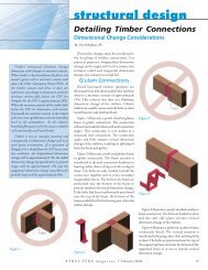
Consideration shall be given to the potential effects of shrinkage and distortion due to changes in<br />
moisture content prior to and after assembly of the structure.<br />
2.3 Notching<br />
2.3.1 Effects on Member Stiffness<br />
The effects of notching on member stiffness with respect to serviceability shall be considered.<br />
2.3.2 Tension or Compression Face Notches<br />
The provisions of the ANSI/AF&PA NDS © shall apply <strong>for</strong> the design of bending members that<br />
are notched across the full width of their tension or compression face. The provisions of<br />
Sections 2.3.3 and 2.3.4 of this Standard shall also apply.<br />
2.3.3 Coped Tension Face Notches<br />
A gradual change in cross section compared with a square notch decreases the actual shear stress<br />
parallel to the grain nearly to that computed <strong>for</strong> an unnotched bending member with the same net<br />
depth d n . Such a gradual change shall be achieved by providing smooth transitions between<br />
surfaces with no overcuts at reentrant corners.<br />
TFEC 1-2010 Standard Page 10 June 2010
2.3.4 Partial-width Notches<br />
A partial-width notch is a notch on the face of a bending member that does not extend across the<br />
full width of the face (see Figure 2A).<br />
Figure 2A Partial-width notches<br />
w 1<br />
See Sec. 2.3.4.1<br />
w 2<br />
w 3<br />
d<br />
See Sec. 2.3.4.2 See Sec. 2.3.4.3<br />
b<br />
2.3.4.1 The width w 1 of a partial-width notch on the tension or compression face of a bending<br />
member shall not exceed one-third the breadth b of the member. The flexural and shear<br />
capacities of the member shall be determined by the principles of engineering mechanics<br />
using the net cross section of the member at the notch.<br />
2.3.4.2 A partial-width notch on the lateral face of a bending member shall have width w 2 no<br />
greater than d/4. The flexural and shear capacities of the member shall be determined by<br />
the principles of engineering mechanics using the net cross section of the member at the<br />
notch.<br />
2.3.4.3 A partial-width notch extending from the compression face down the lateral face of a<br />
bending member shall have a width w 3 not exceeding b/4. The flexural and shear<br />
TFEC 1-2010 Standard Page 11 June 2010
capacities of the member shall be determined by the principles of engineering mechanics<br />
using an effective rectangular cross section consisting of the depth of the member and the<br />
net breadth b n of the member at the notch. If the clear distance between such notches on<br />
opposing faces of the member exceeds 6b, the notches shall be regarded as occurring at<br />
different cross sections (see Figure 2B-a). If the clear distance between notches on<br />
opposing faces of the member is less than 6b, the notches shall be regarded as occurring<br />
at the same cross section location (see Figure 2B-b)<br />
TFEC 1-2010 Standard Page 12 June 2010
3.0 Connections<br />
3.1 General<br />
Chapter 3 applies to the engineering design of connections using wood-on-wood bearing and<br />
wood fasteners, including pegs and wedges, <strong>for</strong> load transfer. The provisions of the<br />
ANSI/AF&PA NDS © shall apply <strong>for</strong> the design of connections using metallic fasteners and<br />
metal connector plates.<br />
3.1.1 Terminology<br />
3.1.1.1 “Edge distance” is the distance l v from the edge of a member or the inside face of a<br />
housing to the center of the nearest fastener, measured perpendicular to grain. When a<br />
member is loaded perpendicular to grain, the loaded edge shall be defined as the edge in<br />
the direction toward which the fastener is acting. The unloaded edge shall be defined as<br />
the edge opposite to the loaded edge.<br />
3.1.1.2 “End distance” is the distance l e measured parallel to grain from the square-cut end of a<br />
member to the center of the nearest fastener. For a member with a tapered-cut end, “end<br />
distance” is the minimum distance measured parallel to grain from the face of the cut end<br />
of a member to a diametrical line oriented perpendicular to grain through the center of the<br />
nearest fastener (see Figure 3A).<br />
TFEC 1-2010 Standard Page 13 June 2010
Figure 3A End distance <strong>for</strong> tapered member ends<br />
l e1<br />
l =<br />
e<br />
min( l<br />
e1 , l<br />
e 2<br />
, l<br />
e 3<br />
, l<br />
e 4<br />
)<br />
l e2<br />
l e3<br />
l e4<br />
3.1.2 Installation of Pegs<br />
3.1.2.1 Holes <strong>for</strong> pegs shall be sized such that pegs are held securely by friction after installation,<br />
but pegs shall not be damaged by crushing, mushrooming, flexure, or splitting as they are<br />
driven into the hole.<br />
3.1.2.2 Draw boring shall be permitted where it can be demonstrated by full-scale or prototype<br />
tests or extensive experience in use that wood splitting in the tenon and damage to the<br />
peg do not occur and that the strength of the connection is not compromised.<br />
3.1.3 Installation of Wedges<br />
3.1.3.1 The opening in the receiving member <strong>for</strong> a wedge shall be sized such that the wedge is<br />
held in place by direct bearing of the wedge against endgrain inside the opening of the<br />
receiving member. Tension perpendicular to grain in the receiving member through<br />
direct bearing of the wedge shall not be permitted.<br />
TFEC 1-2010 Standard Page 14 June 2010
3.1.3.2 Joint detailing and assembly shall be as required to prevent splitting of the tenon, spline,<br />
or other joint material that receives the wedge as a result of wedge installation.<br />
3.1.4 Connection Design<br />
3.1.4.1 Design of mortise and tenon connections <strong>for</strong> shear or tension shall con<strong>for</strong>m to the<br />
provisions of Sections 3.3 through 3.6 of this Standard.<br />
3.1.4.2 Design of other connections (dovetails, scarfs, laps, etc.) shall be according to the<br />
principles of engineering mechanics with appropriate consideration <strong>for</strong> stress<br />
concentrations from notching.<br />
3.2 Withdrawal<br />
3.2.1 Prohibition of Withdrawal Loading<br />
Joint detailing and assembly that may result in withdrawal loading of a peg or wedge is<br />
prohibited.<br />
3.3 Mortise and Tenon Connections Loaded in Shear<br />
3.3.1 Load Transfer by Direct Bearing<br />
Transfer of shear load in a tenoned member to a mortised member shall be achieved by direct<br />
bearing of the tenon within the mortise or by direct bearing of the tenoned member on a mortise<br />
housing.<br />
3.3.2 Shear Capacity<br />
The shear capacity of the tenoned member shall be determined based on the breadth of the<br />
bearing surface of the tenoned member supported by the mortised member.<br />
TFEC 1-2010 Standard Page 15 June 2010
3.3.3 Strength Contribution of Pegs<br />
Pegs shall not be considered to contribute to the shear strength of the tenoned member.<br />
3.3.4 Connection Detailing<br />
Pegs in connections in which the tenoned member is loaded in shear shall be located as close as<br />
practicable to the bearing surface.<br />
3.4 Mortise and Tenon Connections Loaded in Tension<br />
3.4.1 Yield Limit Equations<br />
Transfer of tension load in a tenoned member to a mortised member shall be permitted to be<br />
achieved by lateral load transfer through one or more pegs. The nominal value Z <strong>for</strong> one peg<br />
shall be permitted to be computed using the equations of Table 3A provided that:<br />
(a)<br />
(b)<br />
(c)<br />
(d)<br />
faces of the tenon and mortise are in close contact<br />
the load acts perpendicular to the axis of the peg<br />
the peg is loaded in double shear<br />
edge distance, end distance, and spacing are in accordance with provisions of Sec.<br />
3.4.8<br />
(e)<br />
the penetration length of the peg in the mortise side wall on each side of the tenon<br />
equals at least the thickness of the tenon<br />
(f)<br />
(g)<br />
the size and species of the pegs in a multiple-peg joint are identical<br />
the peg diameter is no less than 0.75 inches and no greater than 1.25 inches.<br />
TFEC 1-2010 Standard Page 16 June 2010
(h)<br />
the tension capacity of the tenon at its net cross section (see NDS ® Section 3.1.2) is<br />
sufficient to resist the applied load.<br />
The nominal design value Z <strong>for</strong> one peg shall be the minimum computed yield value using<br />
equations in Table 3A. The capacity of the connection shall be the capacity of one peg times the<br />
number of pegs in the connection.<br />
TFEC 1-2010 Standard Page 17 June 2010
Table 3A Yield Limit Equations, Double Shear<br />
Yield Mode<br />
Capacity<br />
Yield Mode<br />
Capacity<br />
I m<br />
Z =<br />
D lmF<br />
R<br />
d<br />
em<br />
(3.4-1)<br />
2k<br />
D ls<br />
Fem<br />
III s Z = 3<br />
(3.4-3)<br />
2 + R R<br />
( e<br />
) d<br />
I s<br />
2D lsF<br />
Z =<br />
R<br />
d<br />
es<br />
(3.4-2)<br />
V<br />
2<br />
πD<br />
F<br />
Z =<br />
2R<br />
d<br />
yv<br />
(3.4-4)<br />
Notes:<br />
R d<br />
= 4.0K<br />
= 3.2 K<br />
= 3.5 K<br />
θ<br />
θ<br />
θ<br />
(Modes<br />
(Mode<br />
I<br />
III<br />
(Mode V)<br />
m<br />
s<br />
)<br />
and<br />
I<br />
s<br />
)<br />
(3.4-5)<br />
K<br />
= 1 θ<br />
θ<br />
+<br />
( / 360 )<br />
(3.4-6)<br />
k<br />
3<br />
= −1<br />
+<br />
( + R ) 2Fyb<br />
( 2 + Re<br />
)<br />
2 1<br />
R<br />
e<br />
e<br />
+<br />
3F<br />
l<br />
2<br />
em s<br />
D<br />
2<br />
(3.4-7)<br />
F<br />
yv<br />
= 4850 GpGt<br />
0.75<br />
(3.4-8)<br />
D = peg diameter (in)<br />
F yb = yield strength of the peg in bending (psi)<br />
R e = F em /F es<br />
l m = tenon breadth (in)<br />
l s = minimum mortise side wall thickness on one side of tenon (in)<br />
F em = tenon dowel bearing strength parallel to grain (psi)<br />
F es = mortise side wall dowel bearing strength perpendicular to grain (psi)<br />
θ = maximum angle (0° ≤ θ ≤ 90°) of load to grain <strong>for</strong> any member in a connection (deg)<br />
F yv = effective yield strength of the peg in shear (psi)<br />
G p = specific gravity of the peg material<br />
G t = specific gravity of the timber material<br />
TFEC 1-2010 Standard Page 18 June 2010
3.4.2 Dowel Bearing Strength<br />
Dowel bearing strength F es and F em used in the yield limit equations shall be determined as<br />
follows. For tenons in a mortise and tenon connection with the tenon loaded in tension, F em =<br />
F e|| given by<br />
1.32<br />
F e<br />
= G<br />
(3.4-9)<br />
||<br />
4770 p<br />
For mortised members in a mortise and tenon connection with the tenon loaded in tension, F es =<br />
F e┴ given by<br />
F =<br />
0.50<br />
e⊥ 4900G<br />
pGt<br />
(3.4-10)<br />
3.4.3 Dowel Bearing Strength at an Angle to Grain<br />
When a mortised member is loaded at an angle to the grain, the dowel bearing strength F eθ <strong>for</strong><br />
the member shall be determined as follows:<br />
Fe<br />
||<br />
Fe<br />
⊥<br />
F<br />
eθ =<br />
(3.4-11)<br />
2<br />
2<br />
F sin θ + F cos θ<br />
e||<br />
e⊥<br />
where θ is the angle between the direction of load and the direction of grain (the longitudinal<br />
axis of the member).<br />
3.4.4 Dowel Bearing Length<br />
3.4.4.1 Dowel bearing length in the main member and side member(s) represent the length of<br />
dowel bearing perpendicular to the applied load. The length of dowel bearing shall not<br />
include the tapered tip of a peg.<br />
3.4.4.2 Dowel bearing length l m in the main member shall be taken as the thickness of the tenon.<br />
TFEC 1-2010 Standard Page 19 June 2010
3.4.4.3 Dowel bearing length l s in the side member shall be taken as the minimum of the two<br />
penetration lengths in the side walls of the mortise.<br />
3.4.5 Bending Yield Strength of Pegs<br />
3.4.5.1 Bending yield strength F yb <strong>for</strong> wood pegs shall be based on yield strength derived using<br />
methods provided in ASTM F 1575 (Reference 3).<br />
3.4.6 Peg Diameter<br />
3.4.6.1 For nominally round pegs, peg diameter D shall be taken as the mean diameter of the<br />
peg.<br />
3.4.6.2 For octagonal or other faceted cross-section pegs, peg diameter D shall be the minimum<br />
dimension measured across the peg between two parallel faceted faces.<br />
3.4.7 Seasoning and Creep Effects<br />
The effects of seasoning and creep on the serviceability of mortise and tenon connections loaded<br />
in tension shall be considered. The possible redistribution of <strong>for</strong>ces due to long-term deflection<br />
of connections shall be examined.<br />
3.4.8 Edge Distance, End Distance and Spacing<br />
Mortise and tenon joints loaded in tension shall be proportioned such that splitting of the wood<br />
members does not occur. In the absence of connection details shown to produce satisfactory<br />
per<strong>for</strong>mance in their intended end use, edge distance and end distance of pegs shall meet the<br />
provisions of the ANSI/AF&PA NDS © , Section 11.5 in which the fastener diameter shall be<br />
taken as the diameter of a steel dowel of lateral design capacity equivalent to that of one wood<br />
TFEC 1-2010 Standard Page 20 June 2010
peg used in the same connection. Peg spacing shall be based on the provisions of ANSI/AF&PA<br />
NDS © , Section 11.5 using the peg diameter directly.<br />
3.4.9 Adjustment Factors <strong>for</strong> Peg Connections<br />
The nominal design capacity Z <strong>for</strong> a connection shall be multiplied by all applicable adjustment<br />
factors to determine the allowable design value Z′. Equation (3.4-12) specifies the adjustment<br />
factors that apply to the nominal design value Z.<br />
Z<br />
'<br />
[ C C C C ]<br />
= Z × C<br />
D<br />
M<br />
t<br />
g<br />
Δ<br />
(3.4-12)<br />
The actual load applied to a connection shall not exceed the allowable design value Z′ <strong>for</strong> the<br />
connection.<br />
3.4.9.1 Load Duration Factor, C D : The nominal design value Z shall be multiplied by the load<br />
duration factor C D specified in Section 2.3.2 of the ANSI/AF&PA NDS © . The impact<br />
load duration factor shall not apply to connections.<br />
3.4.9.2 Wet Service Factor, C M : Nominal design values are <strong>for</strong> connections in wood seasoned to<br />
a moisture content of 19% or less and used under continuously dry conditions, as in most<br />
covered structures. For connections in wood that is unseasoned or partially seasoned, or<br />
when connections are exposed to wet service conditions in use, the nominal design value<br />
shall be multiplied by the wet service factor C M specified in Table 3B.<br />
TFEC 1-2010 Standard Page 21 June 2010
Table 3B Wet Service Factor<br />
Moisture Content<br />
At Time of Connection Assembly<br />
In Service<br />
C m<br />
≤ 19%<br />
≤19%<br />
1.0<br />
>19%<br />
any<br />
≤19%<br />
>19%<br />
see Note<br />
0.7<br />
Note: Consideration shall be given to any potential strength<br />
reduction caused by restraint of shrinkage in pegged connections<br />
when the moisture content at the time of assembly exceeds 19%<br />
and the moisture content during service will be less than or equal<br />
to 19%.<br />
3.4.9.3 Temperature Factor, C t : Nominal design values shall be multiplied by the temperature<br />
factors C t in Table 10.3.4, ANSI/AF&PA NDS © , <strong>for</strong> connections that will experience<br />
sustained exposure to elevated temperatures up to 150°F.<br />
3.4.9.4 Group Action Factor, C g : Nominal design values shall be multiplied by the group action<br />
factor C g defined in Section 10.3.6, ANSI/AF&PA NDS © , <strong>for</strong> connections with multiple<br />
pegs in a row parallel to the line of applied <strong>for</strong>ce.<br />
3.4.9.5 Geometry Factor, C Δ : When the end distance, edge distance or spacing provided <strong>for</strong> peg<br />
connections is less than the minimum required <strong>for</strong> full design value, but greater than the<br />
minimum required <strong>for</strong> reduced design value, nominal design values shall be multiplied by<br />
the smallest applicable geometry factor determined from the end distance, edge distance<br />
TFEC 1-2010 Standard Page 22 June 2010
and spacing requirements. The smallest geometry factor, specified in Section 11.5.1 of<br />
the ANSI/AF&PA NDS © , <strong>for</strong> any peg in a group shall apply to all pegs in the group.<br />
3.4.10 Tenon size and quality<br />
3.4.10.1 Tenon Size: The thickness of a tenon shall not exceed one-third the breadth of the face<br />
of the mortised member that receives the tenon.<br />
3.4.10.2 Tenon Quality: Tenons shall be fabricated in a manner and location such that the<br />
strength of the tenon is not disproportionately reduced from that of the member due to<br />
the presence, size, and location of knots, shakes, slope of grain, pith, and other defects.<br />
3.4.11 Mortise Placement<br />
Mortises shall be placed such that the minimum side-wall width w s on each side of the mortise is<br />
not less than the width w m of the mortise (see Figure 3B).<br />
TFEC 1-2010 Standard Page 23 June 2010
Figure 3B Mortise Placement<br />
w s<br />
w m<br />
w s<br />
3.5 Seasoning Effects<br />
For connections fabricated from unseasoned lumber, consideration shall be given to the potential<br />
effects of distortion due to shrinkage or warping prior to and after assembly of the structure. In<br />
addition, the potential effects of seasoning on the assembled connection shall be considered. In<br />
particular the possible loss of bearing contact between two members and the change in<br />
orientation of bearing surfaces shall be considered.<br />
TFEC 1-2010 Standard Page 24 June 2010
4.0 Design <strong>for</strong> Lateral Loads<br />
4.1 Stand-Alone <strong>Timber</strong> <strong>Frame</strong>s<br />
Stand-alone timber frames have been shown to have limited stiffness under lateral loads due to<br />
the relatively low stiffness of wood-pegged joints. Hence, the effects of joint stiffness shall be<br />
considered in the structural analysis of stand-alone timber frames to assure that the strength and<br />
serviceability of the structural system are adequate <strong>for</strong> the intended end use.<br />
4.2 <strong>Timber</strong> <strong>Frame</strong>s and Diaphragm - Shear Wall Systems<br />
The strength and stiffness of timber frames constructed with diaphragms and shear walls to resist<br />
lateral load shall be determined by one of the following methods.<br />
4.2.1 Coupled <strong>Timber</strong> <strong>Frame</strong> and Diaphragm - Shear Wall System<br />
<strong>Timber</strong> frames and their jointed connections that resist lateral loads shall be designed <strong>for</strong> strength<br />
based on allowable stresses <strong>for</strong> the frame members and connections. Designated shear walls and<br />
diaphragm(s) shall be designed <strong>for</strong> strength based on the allowable shear load <strong>for</strong> the individual<br />
shear walls and diaphragm(s). Design <strong>for</strong>ces in the timber frames, shear walls, and diaphragm(s)<br />
shall be determined by the use of a diaphragm-frame interaction structural model that includes<br />
the relative effects of shear wall (end wall) stiffness and roof diaphragm stiffness on the lateral<br />
load distribution to the lateral-load-resisting components.<br />
4.2.2 Lean-on <strong>Timber</strong> <strong>Frame</strong> System<br />
For timber frames that are intended to lean on a diaphragm - shear wall system <strong>for</strong> lateral<br />
support, the diaphragm - shear wall system shall be designed to resist all lateral loads on the<br />
building system. In addition, connections between the timber frame and the diaphragm - shear<br />
TFEC 1-2010 Standard Page 25 June 2010
wall system shall be adequate to transfer <strong>for</strong>ces from the timber frame to the diaphragm-shear<br />
wall system.<br />
TFEC 1-2010 Standard Page 26 June 2010
Appendix A – Glossary<br />
COPE – a notch cut on the tension face of a bending member at the member’s bearing surface.<br />
DRAW BORING – traditional framing technique in which the peg hole in the tenon is<br />
deliberately offset from the peg hole in the mortise to draw a joint tight when assembled and<br />
fastened with a tapered pin or peg, and to hold the joint tight after shrinkage of the mortised<br />
member occurs.<br />
EDGE DISTANCE –The distance from the center of a peg hole to the edge of the member, or to<br />
the edge of the housing, in a mortised member measured perpendicular to the grain direction.<br />
END DISTANCE –The distance from the center of a peg hole to the end of the member,<br />
measured parallel to the grain direction.<br />
HOUSING – a recess in a supporting member to permit the full width of an adjoining member to<br />
bear on the supporting member.<br />
LATERAL FACE – a face of a structural member that is parallel to the plane of the loads on the<br />
bending member. The lateral face is perpendicular to the tension and compression faces.<br />
LEAN-ON SYSTEM – a structural system that provides no resistance to lateral load. A lean-on<br />
system distributes lateral load to another structural system and relies on that system <strong>for</strong> structural<br />
stability.<br />
MOISTURE CONTENT – the weight of water in the cell walls and cavities of wood, expressed<br />
as a percentage of oven-dry weight.<br />
MORTISE – a rectangular notch, slot, or hole cut into a structural component that will accept a<br />
corresponding tenon or spline.<br />
TFEC 1-2010 Standard Page 27 June 2010
MORTISE AND TENON (M&T) – a joint in which a projection (tenon) on one end of a piece is<br />
inserted into a notch, slot or hole (mortise) in another piece.<br />
MORTISE SIDE WALL – the portion of the mortised member between the inside face of the<br />
mortise and the outside face of the member.<br />
NOTCH – an area in a timber where a portion of the cross-section has been cut away, typically<br />
as part of joinery between two intersecting members.<br />
NOTCH, FULL-WIDTH – a notch on the tension or compression face of a bending member that<br />
extends across the full width of the face.<br />
NOTCH, PARTIAL-WIDTH – a notch on the tension or compression face of a bending member<br />
that does not extend across the full width of the face.<br />
PEG – a cylindrical or slightly tapered wooden dowel or pin with round, octagonal, or other<br />
faceted cross section.<br />
SCARF JOINT – a joint made by notching and lapping two timbers such that the longitudinal<br />
axes of the timbers are collinear.<br />
SPECIFIC GRAVITY (G) – the ratio of the ovendry weight of a sample of wood to the weight of<br />
a volume of water equal to the volume of the sample of wood at a specified moisture content.<br />
SPLINE (aka: FREE TENON) – a lumber or engineered wood element placed in slot cuts,<br />
grooves, dados, etc. to secure joints between two components.<br />
STAND-ALONE TIMBER FRAME – a timber frame structure designed to resist lateral loads<br />
without the use of shear walls or other supplementary structural systems.<br />
TFEC 1-2010 Standard Page 28 June 2010
TENON – a projecting square or rectangular end on a timber that fits into a mortise to complete<br />
the connection of two pieces.<br />
TIMBER FRAME – a structural building frame system or portion thereof that is composed of<br />
heavy timber members in which connections between interlocking members are typically created<br />
by carpenter-style joinery using wood pegs and wood wedges but may be supplemented with<br />
some metallic fastener components.<br />
WEDGE – a tapered wood element with rectangular cross section used to secure through-tenons,<br />
through-splines and scarf joints.<br />
TFEC 1-2010 Standard Page 29 June 2010
Appendix B – References<br />
1. ANSI/AF&PA, NDS © -2005, National Design <strong>Specification</strong> <strong>for</strong> Wood <strong>Construction</strong>, AF&PA,<br />
Washington, D. C.<br />
2. ASTM Standard D5764-1997, Test Method <strong>for</strong> Evaluating Dowel Bearing Strength of Wood<br />
and Wood Base Products, ASTM, West Conshohocken, PA, 1997.<br />
3. ASTM Standard F1575-2003, Standard Test Method <strong>for</strong> Determining Bending Yield<br />
Moment of Nails, ASTM, Conshohocken, PA, 1995.<br />
4. SEI/ASCE Standard 7-2005, Minimum Design Loads <strong>for</strong> Buildings and Other Structures,<br />
American Society of Civil Engineers, Reston, VA.<br />
5. National Institute of Standards and Technology Voluntary Product Standard PS 20-05,<br />
American Softwood Lumber Standard, Washington, DC, 2005.<br />
6. SEI/ASCE Standard 32-02, Design Loads on Structures During <strong>Construction</strong>, American<br />
Society of Civil Engineers, Reston, VA.<br />
7. AITC 117-2004 - Standard <strong>Specification</strong>s <strong>for</strong> Structural Glued Laminated <strong>Timber</strong> of<br />
Softwood Species, AITC, Centennial, CO.<br />
8. AITC 119-96 – Standard <strong>Specification</strong>s <strong>for</strong> Structural Glued Laminated <strong>Timber</strong> of Hardwood<br />
Species, AITC, Centennial, CO, 1985.<br />
9. ANSI/AITC Standard A190.1-2002, Structural Glued Laminated <strong>Timber</strong>, AITC, Centennial,<br />
CO, 1992.<br />
TFEC 1-2010 Standard Page 30 June 2010