Ducted analog/electronic installation manual (783 kb) - Bryant RV ...
Ducted analog/electronic installation manual (783 kb) - Bryant RV ...
Ducted analog/electronic installation manual (783 kb) - Bryant RV ...

You also want an ePaper? Increase the reach of your titles
YUMPU automatically turns print PDFs into web optimized ePapers that Google loves.
ANALOG DUCTED INSTALLATION INSTRUCTIONS<br />
9. WIRING OF CONTROL SYSTEM<br />
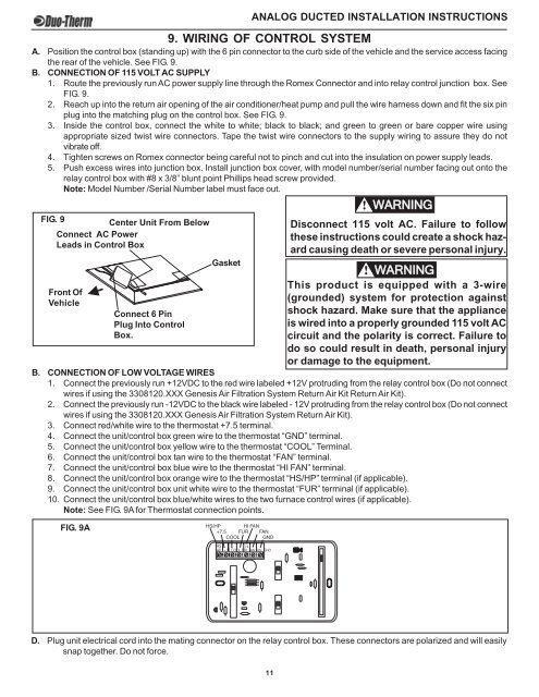
A. Position the control box (standing up) with the 6 pin connector to the curb side of the vehicle and the service access facing<br />
the rear of the vehicle. See FIG. 9.<br />
B. CONNECTION OF 115 VOLT AC SUPPLY<br />
1. Route the previously run AC power supply line through the Romex Connector and into relay control junction box. See<br />
FIG. 9.<br />
2. Reach up into the return air opening of the air conditioner/heat pump and pull the wire harness down and fit the six pin<br />
plug into the matching plug on the control box. See FIG. 9.<br />
3. Inside the control box, connect the white to white; black to black; and green to green or bare copper wire using<br />
appropriate sized twist wire connectors. Tape the twist wire connectors to the supply wiring to assure they do not<br />
vibrate off.<br />
4. Tighten screws on Romex connector being careful not to pinch and cut into the insulation on power supply leads.<br />
5. Push excess wires into junction box. Install junction box cover, with model number/serial number facing out onto the<br />
relay control box with #8 x 3/8” blunt point Phillips head screw provided.<br />
Note: Model Number /Serial Number label must face out.<br />
! WARNING<br />
FIG. 9<br />
Center Unit From Below<br />
Connect AC Power<br />
Leads in Control Box<br />
Front Of<br />
Vehicle<br />
Gasket<br />
Disconnect 115 volt AC. Failure to follow<br />
these instructions could create a shock hazard<br />
causing death or severe personal injury.<br />
! WARNING<br />
This product is equipped with a 3-wire<br />
(grounded) system for protection against<br />
shock hazard. Make sure that the appliance<br />
is wired into a properly grounded 115 volt AC<br />
circuit and the polarity is correct. Failure to<br />
do so could result in death, personal injury<br />
or damage to the equipment.<br />
B. CONNECTION OF LOW VOLTAGE WIRES<br />
1. Connect the previously run +12VDC to the red wire labeled +12V protruding from the relay control box (Do not connect<br />
wires if using the 3308120.XXX Genesis Air Filtration System Return Air Kit Return Air Kit).<br />
2. Connect the previously run -12VDC to the black wire labeled - 12V protruding from the relay control box (Do not connect<br />
wires if using the 3308120.XXX Genesis Air Filtration System Return Air Kit).<br />
3. Connect red/white wire to the thermostat +7.5 terminal.<br />
4. Connect the unit/control box green wire to the thermostat “GND” terminal.<br />
5. Connect the unit/control box yellow wire to the thermostat “COOL” Terminal.<br />
6. Connect the unit/control box tan wire to the thermostat “FAN” terminal.<br />
7. Connect the unit/control box blue wire to the thermostat “HI FAN” terminal.<br />
8. Connect the unit/control box orange wire to the thermostat “HS/HP” terminal (if applicable).<br />
9. Connect the unit/control box unit white wire to the thermostat “FUR” terminal (if applicable).<br />
10. Connect the unit/control box blue/white wires to the two furnace control wires (if applicable).<br />
Note: See FIG. 9A for Thermostat connection points.<br />
FIG. 9A<br />
Connect 6 Pin<br />
Plug Into Control<br />
Box.<br />
D. Plug unit electrical cord into the mating connector on the relay control box. These connectors are polarized and will easily<br />
snap together. Do not force.<br />
11