Ducted analog/electronic installation manual (783 kb) - Bryant RV ...
Ducted analog/electronic installation manual (783 kb) - Bryant RV ...
Ducted analog/electronic installation manual (783 kb) - Bryant RV ...

You also want an ePaper? Increase the reach of your titles
YUMPU automatically turns print PDFs into web optimized ePapers that Google loves.
FILTER<br />
RESET<br />
CLEAN<br />
FILTER<br />
ANALOG DUCTED INSTALLATION INSTRUCTIONS<br />
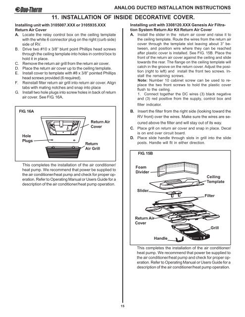
11. INSTALLATION OF INSIDE DECORATIVE COVER.<br />
Installing unit with 3105007.XXX or 3105935.XXX<br />
Return Air Cover<br />
A. Locate the relay control box on the ceiling template<br />
with the white 6 connector plug on the right (curb side)<br />
side of <strong>RV</strong>.<br />
B. Drive two #10 x 3/8” blunt point Phillips head screws<br />
through the ceiling template into holes in control box to<br />
hold it in place.<br />
C. Remove the return air grill from the return air cover.<br />
D. Place the return air cover up to the ceiling template.<br />
E. Install cover to template with #8 x 3/8” pointed Phillips<br />
head screws provided (6 required).<br />
F. Reinstall filter return air grill into return air cover. Align<br />
tabs with mating notches and snap into place<br />
G. Install two hole plugs into screw holes in back of return<br />
air cover. See FIG. 16A.<br />
FIG. 16A<br />
Hole<br />
Plugs<br />
Return Air<br />
Cover<br />
Return<br />
Air Grill<br />
Installing unit with 3308120.XXX Genesis Air Filtration<br />
System Return Air Kit Return Air Cover<br />
A. Install the slider in the return air cover and raise it to<br />
the ceiling template. Route the wires from the return air<br />
cover through the template slot leaving about 3” between,<br />
and position wire where they can be reached<br />
after plastic cover is installed. See FIG. 15B. Place the<br />
front of the return air cover against the ceiling and slide<br />
towards the rear. The flange on the ceiling template will<br />
catch in the groove on the return cover. Adjust the position<br />
(right to left) and install the front two screws. Install<br />
the remaining screws.<br />
Note: Number 10 cabinet screw can be used to replace<br />
the two front screws to hold the plastic cover<br />
flush to the ceiling.<br />
1. Connect together the DC wires (3) black negative<br />
and (3) red positive from the supply, control box and<br />
filter indicator.<br />
B. Insert the filter from the right side (looking toward the<br />
<strong>RV</strong> front) over the wires. Make sure the wires are secured<br />
above the filter and will stay out of its way.<br />
C. Place grill on return air cover and snap in place. Decal<br />
is on end over circuit board.<br />
D. Place slide handle through slots in grill into the slide<br />
posts. Handle will fit in either direction.<br />
FIG. 15B<br />
This completes the <strong>installation</strong> of the air conditioner/<br />
heat pump. We recommend that power be supplied to<br />
the air conditioner/heat pump and check for proper operation.<br />
Refer to Operating Manual or Users Guide for a<br />
description of the air conditioner/heat pump operation.<br />
Foam<br />
Divider<br />
Slider<br />
Ceiling<br />
Template<br />
Filter<br />
Return Air<br />
Cover<br />
Grill<br />
Handle<br />
Micro-Therm Filter System<br />
This completes the <strong>installation</strong> of the air conditioner/<br />
heat pump. We recommend that power be supplied to<br />
the air conditioner/heat pump and check for proper operation.<br />
Refer to Operating Manual or Users Guide for a<br />
description of the air conditioner/heat pump operation.<br />
15