Page 1 CONNECT TVSS Back-UPS ® RS/XS 1200 User's Manual 1 ...
Page 1 CONNECT TVSS Back-UPS ® RS/XS 1200 User's Manual 1 ...
Page 1 CONNECT TVSS Back-UPS ® RS/XS 1200 User's Manual 1 ...

You also want an ePaper? Increase the reach of your titles
YUMPU automatically turns print PDFs into web optimized ePapers that Google loves.
®<br />
1<br />
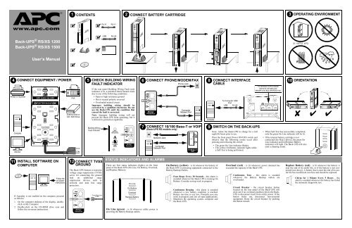
CONTENTS<br />
2 3<br />
<strong>CONNECT</strong> BATTERY CARTRIDGE<br />
OPERATING ENVIRONMENT<br />
w w w.apc.com<br />
✔<br />
✔<br />
RJ-11<br />
RJ-11<br />
<strong>Back</strong>-<strong>UPS</strong> ® <strong>RS</strong>/<strong>XS</strong> <strong>1200</strong><br />
<strong>Back</strong>-<strong>UPS</strong> ® <strong>RS</strong>/<strong>XS</strong> 1500<br />
✔<br />
✔<br />
✔<br />
USB<br />
®<br />
RJ-45<br />
32 - 104 o F (0 - 40 o C)<br />
User’s <strong>Manual</strong><br />
✔<br />
4 <strong>CONNECT</strong> EQUIPMENT / POWER<br />
Printer or Scanner<br />
SURGE ONLY<br />
BATTERY BACKUP<br />
FAX<br />
External Disk or<br />
CD / DVD Drive<br />
53<br />
CHECK BUILDING WIRING<br />
FAULT INDICATOR<br />
If the rear panel Building Wiring Fault (red)<br />
indicator is lit, a potential shock hazard exists<br />
due to one of the following conditions:<br />
• Open or high resistance ground<br />
• Hot or neutral polarity reversed<br />
• Overloaded neutral circuit<br />
Improper building wiring should be<br />
corrected by a qualified electrician. Do not<br />
use the <strong>Back</strong>-<strong>UPS</strong> until the condition that<br />
caused the fault is corrected.<br />
Note: Improper building wiring will not<br />
prevent the <strong>Back</strong>-<strong>UPS</strong> from operating, but it<br />
will limit its protection capability.<br />
6<br />
<strong>TVSS</strong> GND<br />
<strong>CONNECT</strong> PHONE/MODEM/FAX<br />
Wall<br />
Outlet<br />
Modem/<br />
Phone/Fax<br />
Phone Jack<br />
Computer<br />
Modem Port<br />
8<br />
Computer<br />
<strong>CONNECT</strong> INTERFACE<br />
CABLE<br />
To Computer USB<br />
Port<br />
USB RJ-45<br />
Data Port<br />
For connection of APC’s optional<br />
external 24-volt battery pack<br />
(BR24BP) to the <strong>Back</strong>-<strong>UPS</strong> <strong>RS</strong>/<strong>XS</strong> 1500.<br />
BR24BP Battery Pack<br />
10 ORIENTATION<br />
✘ ✔ ✔<br />
Computer<br />
Monitor<br />
Circuit Breaker<br />
Push to Reset<br />
Input: 120V~<br />
12A, 60Hz<br />
Building Wiring<br />
Fault Indicator<br />
Building<br />
Wiring Fault<br />
Wall<br />
Outlet<br />
<strong>TVSS</strong> GND<br />
Modem/<br />
Phone/Fax<br />
7 <strong>CONNECT</strong> 10/100 Base-T or VOIP<br />
(<strong>Back</strong>-<strong>UPS</strong> <strong>RS</strong> models only)<br />
Network Jack<br />
Computer<br />
Network Port<br />
Wall<br />
Outlet<br />
10/100 Base-T<br />
VOIP<br />
9 SWITCH ON THE BACK-<strong>UPS</strong><br />
Note: Allow the <strong>Back</strong>-<strong>UPS</strong> to charge for a full<br />
eight (8) hours prior to use.<br />
Press the front panel Power ON/OFF switch and<br />
observe that the following events occur after<br />
pressing and releasing the switch:<br />
• The green On Line indicator flashes.<br />
• The yellow On Battery indicator lights while<br />
a Self-Test is being performed.<br />
• When Self-Test has successfully completed,<br />
only the green On Line indicator will be lit.<br />
• If the internal battery cartridge is not<br />
connected (see Step 2 above), the green On<br />
Line indicator and red Replace Battery<br />
indicators will light. The <strong>Back</strong>-<strong>UPS</strong> will also<br />
emit a chirping sound.<br />
11 INSTALL SOFTWARE ON<br />
COMPUTER<br />
Follow the<br />
on-screen<br />
instructions.<br />
If Autoplay is not enabled on the computer, proceed<br />
as follows:<br />
1. On the computer desktop of the display, doubleclick<br />
on My Computer.<br />
2. Double-click on the CD-ROM drive icon and<br />
follow the on-screen instructions.<br />
12 <strong>CONNECT</strong> <strong>TVSS</strong><br />
GROUND<br />
The <strong>Back</strong>-<strong>UPS</strong> features a transient<br />
voltage surge-suppression (<strong>TVSS</strong>)<br />
screw for connecting the ground<br />
lead on additional surge<br />
suppression devices such as<br />
network and data line surge<br />
protectors.<br />
Wall<br />
Outlet<br />
<strong>TVSS</strong> GND<br />
Modem/<br />
Phone/Fax<br />
From Data Line<br />
<strong>TVSS</strong><br />
STATUS INDICATO<strong>RS</strong> AND ALARMS<br />
There are four status indicators (lights) on the front<br />
panel of the <strong>Back</strong>-<strong>UPS</strong> (On Line, On Battery, Overload,<br />
and Replace Battery).<br />
On Line<br />
On Battery<br />
Overload<br />
Replace Battery<br />
On Line (green) - is lit whenever utility power is<br />
powering the Battery <strong>Back</strong>up outlets.<br />
On Battery (yellow) - is lit whenever the battery of<br />
the <strong>Back</strong>-<strong>UPS</strong> is powering equipment connected to the<br />
Battery <strong>Back</strong>up Outlets.<br />
Four Beeps Every 30 Seconds - this alarm is<br />
sounded whenever the <strong>Back</strong>-<strong>UPS</strong> is running On<br />
Battery. Consider saving work in progress.<br />
Continuous Beeping - this alarm is sounded<br />
whenever a low battery condition is reached.<br />
Battery run-time is very low. Promptly save any<br />
work in progress and exit all open applications.<br />
Shutdown the operating system, computer and<br />
the <strong>Back</strong>-<strong>UPS</strong>.<br />
Overload (red) - is lit whenever power demand has<br />
exceeded the capacity of the <strong>Back</strong>-<strong>UPS</strong>.<br />
Continuous Tone - this alarm is sounded<br />
whenever the Battery <strong>Back</strong>up outlets are<br />
overloaded.<br />
Circuit Breaker - the circuit breaker button<br />
located on the rear panel of the <strong>Back</strong>-<strong>UPS</strong> will<br />
stick out if an overload condition forces the <strong>Back</strong>-<br />
<strong>UPS</strong> to disconnect itself from utility power. If the<br />
button sticks out, disconnect non-essential<br />
equipment. Reset the circuit breaker by pushing<br />
the button inward.<br />
Replace Battery (red) - is lit whenever the battery is<br />
near the end of its useful life, or if the battery is not connected<br />
(see above). A battery that is near the end of its useful<br />
life has insufficient run-time and should be replaced.<br />
Chirps for 1 Minute Every 5 Hours - this<br />
alarm is sounded whenever the battery has failed<br />
the automatic diagnostic test.
TROUBLESHOOTING<br />
Problem Possible Cause Corrective Action<br />
<strong>Back</strong>-<strong>UPS</strong> will not switch on. <strong>Back</strong>-<strong>UPS</strong> not connected to AC power source. Ensure the <strong>Back</strong>-<strong>UPS</strong> is securely connected to an AC outlet.<br />
<strong>Back</strong>-<strong>UPS</strong> circuit breaker “tripped”.<br />
Disconnect non-essential equipment from the <strong>Back</strong>-<strong>UPS</strong>. Reset<br />
(push in) the rear panel circuit breaker. Switch on the <strong>Back</strong>-<strong>UPS</strong><br />
and plug in devices one at a time. If the circuit breaker trips<br />
again, disconnect the device that caused the breaker to trip.<br />
Utility input voltage quality is out of range. Consider adjusting the transfer voltage and sensitivity. See<br />
Transfer Voltage and Sensitivity Adjustment.<br />
<strong>Back</strong>-<strong>UPS</strong> does not power<br />
essential equipment during an<br />
outage.<br />
<strong>Back</strong>-<strong>UPS</strong> operates on battery<br />
although utility power exists.<br />
<strong>Back</strong>-<strong>UPS</strong> does not provide<br />
expected backup time.<br />
Red Replace Battery indicator is<br />
flashing. Green On Line indicator<br />
is on.<br />
Red Replace Battery indicator is<br />
on.<br />
Red Overload indicator is on or<br />
flashing.<br />
Green On Line indicator is on and<br />
all other front panel indicators are<br />
flashing.<br />
Equipment plugged into a Surge Only outlet.<br />
<strong>Back</strong>-<strong>UPS</strong> circuit breaker “tripped”.<br />
Utility input voltage quality is out of range.<br />
<strong>Back</strong>-<strong>UPS</strong> is heavily loaded.<br />
<strong>Back</strong>-<strong>UPS</strong> battery cartridge is discharged due to<br />
recent power outage and has not had time to<br />
recharge.<br />
Battery has reached the end of its life.<br />
Internal battery cartridge is not connected.<br />
Battery has reached the end of its life.<br />
Connected equipment is drawing more power than<br />
the <strong>Back</strong>-<strong>UPS</strong> can provide.<br />
Internal <strong>UPS</strong> fault.<br />
Unplug device from 'Surge Only' outlet and move to a 'Battery<br />
<strong>Back</strong>up' outlet.<br />
Disconnect non-essential equipment from the <strong>Back</strong>-<strong>UPS</strong>. Reset<br />
(push in) the rear panel circuit breaker. Switch the <strong>Back</strong>-<strong>UPS</strong> on<br />
and plug equipment in one-at-a-time. If the circuit breaker trips<br />
again, disconnect the device that caused the breaker to trip.<br />
Consider adjusting the transfer voltage and sensitivity. See<br />
Transfer Voltage and Sensitivity Adjustment.<br />
Unplug non-essential equipment (printers, scanners, etc) from<br />
the Battery <strong>Back</strong>up outlets and plug into 'Surge Only' outlets.<br />
Charge the battery cartridge for 8 hours. <strong>Back</strong>-<strong>UPS</strong> runtime is<br />
reduced until the battery cartridge is fully charged.<br />
Replace battery cartridge (see Order Replacement Battery<br />
Cartridge).<br />
Connect battery cartridge (see Connect Battery Cartridge).<br />
Replace the battery cartridge (see Order Replacement Battery<br />
Cartridge).<br />
Move one or more equipment power plugs from Battery <strong>Back</strong>up<br />
outlets to Surge Only outlets.<br />
Contact APC Technical Support (see Contact Information).<br />
SPECIFICATIONS<br />
Item<br />
On-line Input Voltage Range<br />
(default settings)<br />
Automatic Voltage Regulation (AVR)<br />
On-line Frequency Range<br />
On-battery Waveshape<br />
Maximum Load<br />
Typical Recharge Time<br />
Operating Temperature<br />
Storage Temperature<br />
Operating / Storage Relative Humidity<br />
Size (H x W x D)<br />
Weight<br />
Specification<br />
83 - 147 Vac (<strong>RS</strong> model)<br />
83 - 139 Vac (<strong>XS</strong> model)<br />
+12% (<strong>XS</strong> model) +12% (<strong>RS</strong> model)<br />
47 - 63 Hz (autosensing)<br />
Stepped Sine Wave<br />
<strong>1200</strong> VA - 780 W 1500 VA - 865 W<br />
<strong>1200</strong> VA: 15 Hours 1500 VA: 8 Hours<br />
32 o to 104 o F<br />
0 o to 40 o C<br />
23 o to 113 o F<br />
-5 o to 45 o C<br />
0 to 95% non-condensing<br />
14.6 x 3.4 x 13.1 inch<br />
37.1 x 8.6 x 33.3 cm<br />
<strong>1200</strong> VA 22 lbs (10 kg)<br />
1500 VA 25 lbs (11 kg)<br />
Shipping Weight <strong>1200</strong> VA 23 lbs (11 kg)<br />
1500 VA 26 lbs (12 kg)<br />
EMI Classification<br />
FCC / DOC Class B Certified<br />
On Battery Run-Time<br />
See http://www.apc.com/product<br />
TRANSFER VOLTAGE AND SENSITIVITY<br />
ADJUSTMENT<br />
In situations where the <strong>Back</strong>-<strong>UPS</strong> or connected equipment appears too sensitive to<br />
input voltage, it may be necessary to adjust the transfer voltage. This is a simple task<br />
requiring use of the front panel pushbutton. To adjust the transfer voltage, proceed as<br />
follows:<br />
1. Plug the <strong>Back</strong>-<strong>UPS</strong> into the utility power source. The <strong>Back</strong>-<strong>UPS</strong> will be in a<br />
Standby Mode (no indicators lit).<br />
2. Press the front panel pushbutton fully inward for 10 seconds. All indicators on the<br />
<strong>Back</strong>-<strong>UPS</strong> will flash to acknowledge going into Programming Mode.<br />
3. The <strong>Back</strong>-<strong>UPS</strong> will then indicate its current Sensitivity Setting, as shown in the<br />
following table.<br />
SERVICE<br />
If the <strong>Back</strong>-<strong>UPS</strong> arrived damaged, notify the carrier.<br />
If the <strong>Back</strong>-<strong>UPS</strong> requires service, do not return it to the dealer. The following<br />
steps should be taken:<br />
1. Consult the Troubleshooting section to eliminate common problems.<br />
2. If the problem persists, go to http://www.apc.com/support/.<br />
3. If the problem still persists, contact APC Technical Support.<br />
• Have the <strong>Back</strong>-<strong>UPS</strong> model number, serial number and date of purchase<br />
available. Be prepared to troubleshoot the problem with an APC Technical<br />
Support representative. If this is not successful, APC will issue a Return<br />
Merchandise Authorization (RMA) number and a shipping address.<br />
LIMITED WARRANTY<br />
The standard warranty is two (2) years from the date of purchase. APC’s standard<br />
procedure is to replace the original unit with a factory reconditioned unit. Customers<br />
who must have the original unit back due to the assignment of asset tags and set<br />
depreciation schedules must declare such a need at first contact with an APC Technical<br />
Support representative. APC will ship the replacement unit once the defective unit has<br />
been received by the repair department, or cross-ship upon the receipt of a valid credit<br />
card number. The customer pays for shipping the unit to APC. APC pays ground<br />
freight transportation costs to ship the replacement unit to the customer.<br />
CONTACT INFORMATION<br />
Technical Support<br />
http://www.apc.com/support<br />
Internet<br />
http://www.apc.com<br />
USA / Canada 1.800.800.4272<br />
Mexico 292.0253 / 292.0255<br />
Brazil 0800.12.72.1<br />
Worldwide +1.401.789.5735<br />
ORDER REPLACEMENT BATTERY CARTRIDGE<br />
The battery cartridge typically lasts 3-6 years, shorter if subjected to frequent outages or elevated temperatures. Order part number RBC33.<br />
Please recycle spent battery cartridges.<br />
REPLACE BATTERY CARTRIDGE<br />
Indicators<br />
Flashing<br />
1<br />
(yellow)<br />
2<br />
(yellow,<br />
and red)<br />
3<br />
(yellow,<br />
red, and<br />
red)<br />
Sensitivity<br />
Setting<br />
Input Voltage<br />
Range<br />
(for utility<br />
operation)<br />
<strong>RS</strong> Models<br />
Input Voltage<br />
Range<br />
(for utility<br />
operation)<br />
<strong>XS</strong> Models<br />
Use When<br />
Low 78 - 150 Vac 78 - 142 Vac Input voltage is<br />
extremely low or high.<br />
Not recommended for<br />
computer loads.<br />
Medium<br />
(factory<br />
default)<br />
83 - 147 Vac 83 - 139 Vac <strong>Back</strong>-<strong>UPS</strong> frequently<br />
goes On Battery.<br />
High 88 - 144 Vac 88 - 136 Vac Connected equipment is<br />
sensitive to voltage<br />
fluctuations .<br />
Battery<br />
Cartridge<br />
4. To select the Low Sensitivity setting, press the pushbutton until the yellow<br />
indicator is flashing.<br />
5. To select the Medium Sensitivity setting, press the pushbutton until the yellow<br />
and red indicators (second and third from the top) are flashing.<br />
6. To select the High Sensitivity setting, press the pushbutton until yellow and both<br />
red indicators (bottom three) are flashing.<br />
7. To exit without changing the Sensitivity Setting, press the pushbutton until the<br />
green indicator is flashing.<br />
8. Once in Programming Mode, if the pushbutton is not pressed within 5 seconds,<br />
the <strong>Back</strong>-<strong>UPS</strong> will exit Programming Mode; all indicators will extinguish.<br />
Notice: This device complies with part 68 and 15 of the FCC rules.Operation is subject<br />
to the following two conditions: (1) This device may not cause harmful interference.<br />
(2) This device must accept any interference received, including interference that may<br />
cause undesired operation.<br />
On the bottom of this equipment is a label that contains, among other information, the<br />
FCC registration number and ringer equivalence number (REN) for this equipment. If<br />
requested, this information must be provided to the telephone company.<br />
990-2163 Copyright © 2004 American Power Conversion All rights reserved.<br />
APC and <strong>Back</strong>-<strong>UPS</strong> are registered trademarks of American Power Conversion.<br />
All other trademarks are the property of their respective owners.