ARAG Bravo 400 Instructions - Bargam UK
ARAG Bravo 400 Instructions - Bargam UK
ARAG Bravo 400 Instructions - Bargam UK

Create successful ePaper yourself
Turn your PDF publications into a flip-book with our unique Google optimized e-Paper software.
<strong>Bravo</strong> <strong>400</strong> series computers<br />
with integrated GPS guide<br />
4674X501<br />
4674X701<br />
4674X511<br />
4674X711<br />
4674X721<br />
46742DX1<br />
Software rel. 1.2X<br />
INSTALLATION, use and maintenance
• Symbol legend<br />
SYMBOL LEGEND<br />
= Generic danger<br />
= Warning<br />
= Only for version with nozzle holder control<br />
This manual is an integral part of the equipment to which it refers and must accompany the equipment in case of sale or change of ownership. Keep it for any<br />
future reference; <strong>ARAG</strong> reserves the right to modify product specifications and instructions at any moment and without notice.<br />
2
3<br />
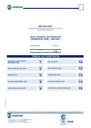
Contents<br />
CONTENTS<br />
• Symbol legend......................................................................................................................................................................................... 2<br />
1 Risks and protections before assembly................................................................................................................................................ 7<br />
2 <strong>Bravo</strong> DSB................................................................................................................................................................................................ 7<br />
3 Intended use............................................................................................................................................................................................. 7<br />
4 Precautions.............................................................................................................................................................................................. 7<br />
5 Contents of the package......................................................................................................................................................................... 7<br />
6 Position on the machine......................................................................................................................................................................... 8<br />
6.1 Recommended system layout.......................................................................................................................................................... 8<br />
6.2 Monitor and control unit location.....................................................................................................................................................11<br />
6.3 Mounting the bracket..................................................................................................................................................................... 12<br />
6.4 Securing the control unit (RCU)..................................................................................................................................................... 12<br />
6.5 Control unit location....................................................................................................................................................................... 12<br />
6.6 Location of oil-hydraulic and pneumatic assemblies...................................................................................................................... 12<br />
6.7 Locating the GPS receiver............................................................................................................................................................. 13<br />
7 Connecting the computer to the agricultural equipment................................................................................................................... 15<br />
7.1 General precautions for cable position.......................................................................................................................................... 15<br />
7.2 Power supply connection............................................................................................................................................................... 15<br />
8 Harness connection to control unit, pneumatic assembly and other available functions................................................................... 16<br />
8.1 Connecting the switches panel...................................................................................................................................................... 16<br />
8.2 Connecting the remote control unit (RCU)..................................................................................................................................... 16<br />
8.3 Connecting the control unit valves................................................................................................................................................. 16<br />
8.4 Connecting the hydraulic valves.................................................................................................................................................... 17<br />
8.5 Connecting the sensors................................................................................................................................................................. 18<br />
8.6 Connecting the cameras................................................................................................................................................................ 18<br />
8.7 SD memory card............................................................................................................................................................................ 19<br />
9 Programming.......................................................................................................................................................................................... 20<br />
9.1 Pre-programming tests and checks............................................................................................................................................... 20<br />
9.2 Switching on.................................................................................................................................................................................. 20<br />
9.3 Switching off.................................................................................................................................................................................. 21<br />
9.4 Using the programming keys......................................................................................................................................................... 21<br />
10 ADVANCED PROGRAMMING - Machine settings................................................................................................................................ 22<br />
10.1 Boom settings................................................................................................................................................................................ 23<br />
10.1.1 Nozzle number.......................................................................................................................................................................................... 23<br />
10.1.2 Output 1 ÷ 13............................................................................................................................................................................................. 23<br />
10.2 Valves .......................................................................................................................................................................................... 24<br />
10.2.1 Boom sections........................................................................................................................................................................................... 24<br />
10.2.2 Auto switch-off........................................................................................................................................................................................... 24<br />
10.2.3 Pressure regulator..................................................................................................................................................................................... 24<br />
10.2.4 Main valve................................................................................................................................................................................................. 25<br />
10.2.5 Selejet........................................................................................................................................................................................................ 25<br />
10.2.6 Section activation time.............................................................................................................................................................................. 25<br />
10.3 GPS receiver................................................................................................................................................................................. 26<br />
10.3.1 Position...................................................................................................................................................................................................... 26<br />
10.3.2 Distance..................................................................................................................................................................................................... 26<br />
10.3.3 Antenna height.......................................................................................................................................................................................... 26<br />
10.3.4 DGPS......................................................................................................................................................................................................... 26<br />
10.4 Flowmeter .................................................................................................................................................................................... 27<br />
10.4.1 Type........................................................................................................................................................................................................... 27<br />
10.4.2 Rate alarms................................................................................................................................................................................................ 27<br />
10.4.3 Constant.................................................................................................................................................................................................... 27<br />
10.5 Pressure sensor ............................................................................................................................................................................ 28<br />
10.5.1 Pressure sensor......................................................................................................................................................................................... 28<br />
10.5.2 Maximum pressure.................................................................................................................................................................................... 28<br />
10.6 Tank............................................................................................................................................................................................... 29<br />
10.6.1 Capacity.................................................................................................................................................................................................... 29<br />
10.6.2 Minimum level alarm.................................................................................................................................................................................. 29<br />
10.7 Filling flowmeter ........................................................................................................................................................................... 30<br />
10.7.1 Type........................................................................................................................................................................................................... 30<br />
10.7.2 Constant.................................................................................................................................................................................................... 30<br />
10.8 Rev counter................................................................................................................................................................................... 31<br />
10.8.1 Rev counter............................................................................................................................................................................................... 31<br />
10.8.2 Constant.................................................................................................................................................................................................... 31<br />
10.8.3 Speed alarms............................................................................................................................................................................................ 31<br />
10.9 Pump Protector ............................................................................................................................................................................ 32<br />
10.10 Maximum speed alarm ................................................................................................................................................................. 32<br />
10.11 Options ......................................................................................................................................................................................... 33<br />
10.11.1 Language.................................................................................................................................................................................................. 33<br />
10.11.2 Timezone................................................................................................................................................................................................... 33<br />
cont'd
CONTENTS<br />
11 USER PROGRAMMING - User menu.................................................................................................................................................... 34<br />
11.1 How does the SELEJET system work........................................................................................................................................... 35<br />
11.2 Treatment settings......................................................................................................................................................................... 36<br />
11.2.1 Status......................................................................................................................................................................................................... 36<br />
11.2.2 Target rate.................................................................................................................................................................................................. 36<br />
11.2.3 Nozzle........................................................................................................................................................................................................ 36<br />
11.3 Nozzles settings ............................................................................................................................................................................ 37<br />
11.3.1 Flowrate - Pressure.................................................................................................................................................................................... 37<br />
11.3.2 Minimum pressure - Maximum pressure................................................................................................................................................... 37<br />
11.4 Working limits ............................................................................................................................................................................... 38<br />
11.4.1 Minimum spraying speed.......................................................................................................................................................................... 38<br />
11.4.2 Minimum regulation pressure.................................................................................................................................................................... 38<br />
11.4.3 Sections overlapping limit......................................................................................................................................................................... 39<br />
11.4.4 Boundary sct. management...................................................................................................................................................................... 39<br />
11.4.5 Intentional overlap..................................................................................................................................................................................... 40<br />
11.5 Alarms ......................................................................................................................................................................................... 41<br />
11.5.1 Steer radius............................................................................................................................................................................................... 41<br />
11.5.2 Nozzle wear check.................................................................................................................................................................................... 41<br />
11.5.3 HDOP level................................................................................................................................................................................................ 42<br />
11.5.4 Nozzle pressure alarm............................................................................................................................................................................... 42<br />
11.6 User preferences .......................................................................................................................................................................... 43<br />
11.6.1 'Guidance' screen..................................................................................................................................................................................... 43<br />
11.6.2 'Spraying' screen...................................................................................................................................................................................... 43<br />
11.6.3 Led bar...................................................................................................................................................................................................... 44<br />
11.6.4 Acoustic alarm........................................................................................................................................................................................... 44<br />
11.6.5 Keypad tone.............................................................................................................................................................................................. 44<br />
11.6.6 Camera 1 / Camera 2................................................................................................................................................................................ 45<br />
11.6.7 User key..................................................................................................................................................................................................... 45<br />
11.7 Memories management ................................................................................................................................................................ 46<br />
11.7.1 Internal memory ....................................................................................................................................................................................... 46<br />
copy files to SD card................................................................................................................................................................................. 46<br />
Move picture to SD card........................................................................................................................................................................... 47<br />
delete internal memory files...................................................................................................................................................................... 48<br />
11.7.2 SD card..................................................................................................................................................................................................... 49<br />
copy files to internal memory.................................................................................................................................................................... 49<br />
delete SD card files................................................................................................................................................................................... 50<br />
Prepare SD card........................................................................................................................................................................................ 51<br />
date logger................................................................................................................................................................................................ 51<br />
11.7.3 Load / Save settings ................................................................................................................................................................................ 52<br />
Load settings from SD card....................................................................................................................................................................... 52<br />
Save settings to SD card........................................................................................................................................................................... 52<br />
11.8 Speed............................................................................................................................................................................................ 53<br />
11.8.1 Source....................................................................................................................................................................................................... 53<br />
Wheel constant.......................................................................................................................................................................................... 53<br />
constant calculation.................................................................................................................................................................................. 53<br />
11.9 Test................................................................................................................................................................................................ 54<br />
11.9.1 Display test .............................................................................................................................................................................................. 54<br />
11.9.2 Keyboard and input test .......................................................................................................................................................................... 54<br />
11.9.3 Signals test ............................................................................................................................................................................................... 55<br />
11.9.4 Software versions...................................................................................................................................................................................... 55<br />
11.9.5 Signals simulation ..................................................................................................................................................................................... 55<br />
12 Use.......................................................................................................................................................................................................... 56<br />
12.1 Computer controls......................................................................................................................................................................... 56<br />
12.2 Using keys..................................................................................................................................................................................... 56<br />
12.3 Operating switches for control unit valves...................................................................................................................................... 57<br />
12.4 Operating switches for hydraulic valves......................................................................................................................................... 57<br />
12.5 Display........................................................................................................................................................................................... 58<br />
12.6 Spraying boom............................................................................................................................................................................... 60<br />
12.7 Spray rate regulation...................................................................................................................................................................... 62<br />
12.8 Importing and using a prescription map........................................................................................................................................ 62<br />
12.9 Spraying a field.............................................................................................................................................................................. 63<br />
4<br />
cont'd
CONTENTS<br />
13 Work functions....................................................................................................................................................................................... 64<br />
13.1 Functions List: PAGE 1.................................................................................................................................................................. 65<br />
13.1.1 F1 Job type.............................................................................................................................................................................................. 65<br />
13.1.2 F1 Job type.............................................................................................................................................................................................. 66<br />
13.1.3 F2 Pause.................................................................................................................................................................................................. 67<br />
13.1.4 F3 Mode................................................................................................................................................................................................................68<br />
13.1.5 F4 Return.................................................................................................................................................................................................. 69<br />
13.1.6 F5 P.O.I .................................................................................................................................................................................................... 70<br />
13.1.7 F6 Align.................................................................................................................................................................................................... 71<br />
13.1.8 F7 Area..................................................................................................................................................................................................... 72<br />
13.1.9 F8 Tank..................................................................................................................................................................................................... 73<br />
13.2 Functions list: PAGE 2.....................................................................................................................................................................74<br />
13.2.1 F1 Job resume......................................................................................................................................................................................... 74<br />
13.2.2 F2 Mark AB............................................................................................................................................................................................................76<br />
13.2.3 F3 2D-3D.................................................................................................................................................................................................. 77<br />
13.2.4 F4 Auto/Man............................................................................................................................................................................................. 78<br />
13.2.5 F6 Day / Night.......................................................................................................................................................................................... 78<br />
13.2.6 F7 GPS..................................................................................................................................................................................................... 79<br />
13.2.7 F8 Pressure........................................................................................................................................................................................................................................79<br />
13.3 Functions list: PAGE 3.................................................................................................................................................................... 80<br />
13.3.1 F1 New job............................................................................................................................................................................................... 80<br />
13.3.2 F2 Waypt................................................................................................................................................................................................................82<br />
13.3.3 F7 Erase................................................................................................................................................................................................... 83<br />
13.3.4 F8 User..................................................................................................................................................................................................... 84<br />
14 Maintenance / diagnostics / repairs..................................................................................................................................................... 85<br />
14.1 Alarm display................................................................................................................................................................................. 85<br />
14.2 Pump failure alarm......................................................................................................................................................................... 85<br />
14.3 Error messages............................................................................................................................................................................. 86<br />
14.3 Troubleshooting............................................................................................................................................................................. 88<br />
14.4 Cleaning rules................................................................................................................................................................................ 88<br />
15 Technical data........................................................................................................................................................................................ 89<br />
15.1 Displayed data and relevant units of measurement....................................................................................................................... 89<br />
16 End-of-life disposal............................................................................................................................................................................... 93<br />
17 Guarantee terms.................................................................................................................................................................................... 93<br />
5
6<br />
Notes
INTRODUCTION<br />
1 Risks and protections before assembly<br />
All installation work must be done with battery disconnected, using suitable tools and any individual protection equipment<br />
deemed necessary.<br />
Use ONLY clean water for treatment tests and simulations: using chemicals during simulated treatment runs can seriously injure<br />
persons in the vicinity.<br />
2 <strong>Bravo</strong> DSB<br />
<strong>ARAG</strong> has designed and manufactured a diagnostics system for <strong>Bravo</strong> series computers and the systems to which they may be connected.<br />
BRAVO DSB (code 467003) provides reliable diagnostics of computer, control unit or the whole system so as to enable the resolution of any potential<br />
problems experienced with the BRAVO DSB system.<br />
3 Intended use<br />
The device you have purchased is a computer which, when connected to a valve or suitable control unit, makes it possible to control all phases of<br />
treatment in agricultural applications directly from the cabin of the agricultural machine in which it is installed.<br />
BRAVO <strong>400</strong> is a satellite navigator which can be used for agricultural purposes thanks to its GPS receiver.<br />
BRAVO <strong>400</strong> is not a road navigator and should only be used on agricultural land.<br />
This device is designed to work on agricultural machinery for crop spraying applications.<br />
The machine is designed and built in compliance with EN ISO 14982 standard (Electromagnetic compatibility - Forestry and<br />
farming machines), harmonized with 2004/108/EC Directive.<br />
4 Precautions<br />
• Do not aim water jets at the equipment.<br />
• Do not use solvents or fuel to clean the case outer surface.<br />
• Do not clean equipment with direct water jets.<br />
• Comply with the specified power voltage (12 Vdc).<br />
• If doing arc-welding, disconnect the connectors from BRAVO <strong>400</strong> and disconnect its power cables.<br />
• Only use <strong>ARAG</strong> genuine spare parts and accessories.<br />
• <strong>Bravo</strong> <strong>400</strong> can control the hydraulic valves that open and close the job boom.<br />
The computer does not feature emergency stop devices: the manufacturer must provide all necessary safety devices for the<br />
hydraulic boom control.<br />
Any time the hydraulic boom section is opened or closed the computer emits an acoustic signal and the display shows the<br />
relevant indication. The manufacturer should also provide acoustic and optical warnings in the vicinity of the boom.<br />
5 Contents of the package<br />
The table below shows the components you will find inside the BRAVO <strong>400</strong> computer package:<br />
Fig. 1<br />
Legend:<br />
1 <strong>Bravo</strong> <strong>400</strong><br />
2 User's guide<br />
3 Control unit (RCU)<br />
with relevant harnesses<br />
3a Connection cable<br />
to oil-hydraulic assembly<br />
3b Connection cable<br />
to control unit<br />
3c Connection cable<br />
to power sensors<br />
3d Connection cable to monitor<br />
4 SD memory card<br />
5 Mounting kit<br />
6 Drive for SD memory card<br />
7 GPS receiver<br />
8 Receiver support<br />
9 Connection cable<br />
to switches panel / monitor<br />
10 Connection cable<br />
to GPS receiver<br />
11a Seals for section valve<br />
connectors<br />
11b Seals for oil-hydraulic valve<br />
connectors<br />
12 Power connector<br />
7
INSTALLATION<br />
6 Position on the machine<br />
6.1 Recommended system layout<br />
ASSEMBLY DIAGRAM FOR CROP SPRAYERS WITH DIAPHRAGM PUMP<br />
Legend:<br />
A Monitor<br />
B Battery<br />
C GPS receiver<br />
D Filling pump<br />
E Oil-hydraulic assembly<br />
F Flowmeter<br />
G Main valve<br />
H External main control<br />
M Pressure sensor<br />
P Control valve<br />
S Speed sensor<br />
T Filling flowmeter<br />
or Pump Protector<br />
U Control unit (RCU)<br />
V1 Camera 1<br />
V2 Camera 2<br />
X RPM sensor or Pump Protector<br />
1-5 Section valve<br />
Fig. 2<br />
ASSEMBLY DIAGRAM FOR CROP SPRAYERS WITH CENTRIFUGAL PUMP<br />
Legend:<br />
A Monitor<br />
B Battery<br />
C GPS receiver<br />
D Filling pump<br />
E Oil-hydraulic assembly<br />
F Flowmeter<br />
G Main valve<br />
H External main control<br />
M Pressure sensor<br />
P Control valve<br />
S Speed sensor<br />
T Filling flowmeter<br />
U Control unit (RCU)<br />
V1 Camera 1<br />
V2 Camera 2<br />
X RPM sensor<br />
1-5 Section valve<br />
Fig. 3<br />
CONT'D<br />
8
INSTALLATION<br />
ASSEMBLY DIAGRAM FOR CROP SPRAYERS WITH DIAPHRAGM PUMP - WITH NOZZLE HOLDER CONTROL<br />
Fig. 4<br />
Legend:<br />
A Monitor<br />
B Battery<br />
C GPS receiver<br />
D Filling pump<br />
E Oil-hydraulic assembly<br />
F Flowmeter<br />
G Main valve (3 ways - 3 wires)<br />
H External main control<br />
M Pressure sensor<br />
P Control valve<br />
S Speed sensor<br />
T Filling flowmeter<br />
or Pump Protector<br />
U Control unit (RCU)<br />
V1 Camera 1<br />
V2 Camera 2<br />
X RPM sensor or Pump Protector<br />
Y Section valve pneumatic assembly:<br />
1÷ 7A Row A section valves<br />
1÷ 7A Row B section valves<br />
Z Selejet nozzle holder<br />
CONT'D<br />
9
INSTALLATION<br />
ASSEMBLY DIAGRAM FOR CROP SPRAYERS WITH CENTRIFUGAL PUMP - WITH NOZZLE HOLDER CONTROL<br />
Fig. 5<br />
Legend:<br />
A Monitor<br />
B Battery<br />
C GPS receiver<br />
D Filling pump<br />
E Oil-hydraulic assembly<br />
F Flowmeter<br />
G Main valve (3 ways - 3 wires)<br />
H External main control<br />
M Pressure sensor<br />
P Control valve<br />
S Speed sensor<br />
T Filling flowmeter<br />
U Control unit (RCU)<br />
V1 Camera 1<br />
V2 Camera 2<br />
X RPM sensor<br />
Y Section valve pneumatic assembly:<br />
1÷ 7A Row A section valves<br />
1÷ 7A Row B section valves<br />
Z Selejet nozzle holder<br />
10
INSTALLATION<br />
6.2 Monitor and control unit location<br />
• The BRAVO <strong>400</strong> series computer must be installed in the machine control cabin. Observe the following precautions:<br />
- do NOT install the monitor in areas where it would be subjected to excessive vibrations or shocks, to prevent any damage or<br />
accidental use of the control keys;<br />
- install the device in a visible position within easy reach by hand; bear in mind that the computer should not obstruct the<br />
operator’s freedom of movement or block his view.<br />
• Control unit (RCU): locate the control unit in the rear side of the machine near the control unit and the oil-hydraulic/pneumatic<br />
assemblies.<br />
Note the connections required for the computer to operate (Fig. 6 and 7), the required length of the cables, and provide adequate<br />
space for connectors cables.<br />
An identification symbol is located next to each connector to indicate its function. For the configuration of the systems, refer to<br />
par. 6.1 - Recommended system layout.<br />
ITEM<br />
CONNECTION POINTS<br />
1 SD memory card<br />
2 Connection to GPS receiver<br />
3<br />
4<br />
5<br />
Connection to cameras<br />
+<br />
External main control<br />
Connection<br />
to switches panel / monitor<br />
Control panel power supply<br />
+<br />
Connections to RCU<br />
Fig. 6<br />
Fig. 7<br />
ITEM<br />
CONNECTION POINTS<br />
6 Monitor<br />
7 Power and sensors<br />
8 Control unit<br />
9 Oil-hydraulic assembly<br />
11
INSTALLATION<br />
6.3 Mounting the bracket<br />
The monitor must be mounted after having fixed the bracket at the desired location (the previous paragraph shows the bracket drilling template).<br />
The bracket must be extracted from the monitor seat (A, Fig. 8) and fixed using the provided screws (B).<br />
Make sure the bracket is securely mounted, fit the monitor on it, and push it in until it locks in place (C).<br />
Fig. 8<br />
6.4 Securing the control unit (RCU)<br />
Observe the control unit assembly sense shown in Fig. 9 (connectors downwards).<br />
Any other kind of positioning is not allowed.<br />
Fig. 9<br />
6.5 Control unit location<br />
The control unit must be fixed with the special brackets supplied and fitted to the unit, positioning it as shown in the manual provided with the assembly.<br />
MAKE SURE TO FOLLOW ALL THE SAFETY INSTRUCTIONS GIVEN IN THE CONTROL UNIT’S MANUAL.<br />
6.6 Location of oil-hydraulic and pneumatic assemblies<br />
The oil-hydraulic and pneumatic assemblies must be installed in the machine in a point protected against weather and the liquid sprayed by the machine.<br />
<strong>ARAG</strong> IS NOT LIABLE FOR ANY DAMAGE CONSEQUENT ON INSTALLATION BY UNQUALIFIED PERSONS. IN CASE OF DAMAGE<br />
TO THE SYSTEM CAUSED BY INCORRECT INSTALLATION OR CONNECTIONS, THE WARRANTY IS AUTOMATICALLY VOIDED.<br />
WARNING! DO NOT CONNECT OIL-HYDRAULIC / PNEUMATIC ASSEMBLIES OTHER THAN THE FORESEEN ONES (SEE <strong>ARAG</strong><br />
GENERAL CATALOGUE).<br />
<strong>ARAG</strong> IS NOT LIABLE FOR DAMAGE TO THE PRODUCT, FAULTS OR RISKS OF ANY NATURE CONSEQUENT ON CONNECTING<br />
THE MODULE TO NON-ORIGINAL RECEIVERS OR THOSE NOT SUPPLIED BY <strong>ARAG</strong>.<br />
12
INSTALLATION<br />
6.7 Locating the GPS receiver<br />
The user must position the GPS receiver as indicated in this manual and make sure the new vehicle height does not interfere<br />
with any obstacle.<br />
Installing the GPS receiver:<br />
Installation of the receiver on agricultural equipment must observe certain basic requirements:<br />
it shall be positioned on the highest position of the agricultural equipment (including trailer); receiving angle toward the sky shall be as large as possible.<br />
180°<br />
Fig. 10<br />
140°<br />
Fig. 11<br />
The receiver shall be installed on vehicle longitudinal axis (Fig. 12).<br />
Fig. 12 Fig. 13<br />
13
INSTALLATION<br />
Securing the GPS receiver:<br />
If the support used for fastening the receiver is in iron or steel, use the supplied magnet. Magnet features a threaded pin on which receiver is to be<br />
mounted, by screwing it on until it locks (Fig. 14).<br />
Make sure that the receiver is mounted to a perfectly flat metal surface, free of any surface treatment capable of reducing the<br />
strength of the magnet itself.<br />
Fig. 14 Fig. 15<br />
If you are not sure that the magnet mounting system is completely secure, you'd better screw pin directly onto the machine chassis, as indicated in<br />
Fig. 16, by drilling and fastening it from inside using an M10 nut.<br />
Fig. 16<br />
The operator is responsible for checking that the mounting system is completely secure. <strong>ARAG</strong> is not liable for damage of any<br />
nature caused by the receiver working free, independently of which mounting system is used.<br />
14
INSTALLATION<br />
7 Connecting the computer to the agricultural equipment<br />
7.1 General precautions for cable position<br />
• Securing the cables:<br />
- secure the harness so that it does not interfere with moving parts;<br />
- route the harnesses in such a way that they cannot come into contact with moving parts.<br />
• Routing the cables to protect against water infiltrations:<br />
- branches in the cable runs must ALWAYS be oriented downwards (Fig. 17a).<br />
Fig. 17a<br />
Fig. 17b<br />
• Fitting the cables to the connection points:<br />
- do not force the connectors by pushing too hard or bending them: the contacts can be damaged and computer operation compromised.<br />
Use ONLY the cables and accessories indicated in the catalogue, having technical features suitable for the use to be made of<br />
them.<br />
7.2 Power supply connection<br />
Inside the package (component 12, Fig. 1) you will find the power connector required for the connection to the machine’s battery;<br />
Fig. 18c shows the drilling template for installing the power connector.<br />
Connect the power connector to the battery wires using two 6 mm faston connectors, as shown in figs. 18a and 18b.<br />
Use the cable provided in the package (component 3, Fig. 1) to connect the computer to its power supply.<br />
Fig. 18a Fig. 18b Fig. 18c<br />
WARNING:<br />
To avoid short circuits, do not connect the power cables to battery before the installation is completed.<br />
Before powering up the computer and control unit, make sure the battery voltage is as specified (12 Vdc).<br />
BRAVO <strong>400</strong> is powered directly from the battery (12 Vdc): it must ALWAYS be switched on from the computer; when finished, switch the computer off<br />
manually using the suitable key on the control panel.<br />
Keeping BRAVO <strong>400</strong> on for long periods of time when the machine is off may run down the tractor battery: be sure to switch off<br />
the computer if the machine is to be left unused with the engine off for some time.<br />
Connect the power source as shown in Fig. 19: the computer must be connected directly to the machine's battery. DO NOT connect the computer<br />
to key-operated switch (15/54).<br />
WARNING:<br />
• The power circuit shall ALWAYS be protected by a 10 A fuse<br />
like the ones for automotive applications.<br />
• All cables connected to the battery shall have a minimum crosssection<br />
of 2.5 sq. mm.<br />
To avoid short-circuits, connect the power cable connector only<br />
after completing installation.<br />
• Use cables with suitable terminals ensuring correct connection<br />
of all wires.<br />
Fig. 19<br />
15
INSTALLATION<br />
8 Harness connection to control unit, pneumatic assembly and other available functions<br />
• Use only the cables provided with the <strong>ARAG</strong> computers.<br />
• Take care not to break, pull, tear or cut the cables.<br />
• Use of unsuitable cables not provided by <strong>ARAG</strong> automatically voids the warranty.<br />
• <strong>ARAG</strong> is not liable for damage to the equipment, persons or animals caused by failure to observe the above instructions.<br />
8.1 Connecting the switches panel<br />
Inside the package (component 9, Fig. 1) you will find the power cable connector required for the connection to the machine's battery.<br />
Fix the connectors (connection points at par. 6.2), properly insert the ring nut and turn it clockwise until it locks.<br />
8.2 Connecting the remote control unit (RCU)<br />
• Open the connector rail (1, Fig. 20).<br />
• Insert the connector (2) into the outlet (3) and<br />
push it: be careful not to bend the contacts<br />
upon insertion.<br />
• Fully tighten the rail (4).<br />
Fig. 20<br />
Connect the harnesses as indicated in par. 6.2; make sure to connect each harness to the relevant outlet on the remote control unit.<br />
In case the insertion proves difficult do not force the connectors and check the indicated position.<br />
8.3 Connecting the control unit valves<br />
• Use <strong>ARAG</strong> valves: use of unsuitable valves not provided by <strong>ARAG</strong> automatically voids the warranty.<br />
<strong>ARAG</strong> is not liable for damage to the equipment, persons or animals caused by failure to observe the above instructions.<br />
• All valve connectors must be equipped with seals before installation (Fig. 22).<br />
• Make sure the seals are correctly fitted to avoid infiltration of water when using the control unit.<br />
Valve 1 Valve 2 Valve 3 Valve 4 Valve 5<br />
Connector 1 shall control the valve which in turn is<br />
connected to the boom section 1, and so on with the<br />
other valves.<br />
Connect "connector 1" to "valve 1", and then the<br />
other connectors, with rising numbers from left to<br />
right: the boom section 1 is the left one looking<br />
the machine from the rear side (Fig. 21).<br />
Boom<br />
section 1<br />
Fig. 21<br />
Boom<br />
section 2<br />
Boom<br />
section 3<br />
Boom<br />
section 4<br />
Boom<br />
section 5<br />
Fix the connectors to the relevant valves according to<br />
the initials indicated in your assembly general diagram<br />
(par. 6.1 - Recommended system layout).<br />
• Remove the protection cap (1, Fig. 22) from the<br />
electric valve.<br />
• Place the seal (2) onto the connector (3), and push<br />
the connector fully on (4): be careful not to bend<br />
the contacts upon insertion on the valve.<br />
• Tighten the screw (5) fully home.<br />
Fig. 22<br />
16
INSTALLATION<br />
• ONLY FOR<br />
<strong>Bravo</strong> <strong>400</strong> can control up to 7 sections with a suitable pneumatic assembly.<br />
WARNING! ! The main valve shall be a 3-wire one (the valve code features a "T" at the end).<br />
Fix the connectors to the relevant valves according to the initials indicated<br />
in your assembly general diagram (par. 6.1 - Recommended system layout).<br />
• Place the seal (1) onto the connector (2), and push the connector fully on (3):<br />
be careful not to bend the contacts upon insertion on the valve.<br />
• Insert the screw into the connector and fully tighten it (4).<br />
Fig. 23<br />
• ONLY FOR SEQUENTIAL VERSION:<br />
WARNING!<br />
The main and section valves connected to the computer shall be of the 3-wire type (the valve code features a "T" at the end).<br />
In case less than 13 section valves are required, always start to connect from section 1 until the last one in sequence.<br />
Example:<br />
- Connections for 8 valves: sec. 1 + 2 + 3 + 4 + 5 + 6 + 7 + 8<br />
- Connections for 11 valves: sec. 1 + 2 + 3 + 4 + 5 + 6 + 7 + 8+ 9 + 10 + 11 etc.<br />
8.4 Connecting the hydraulic valves<br />
<strong>Bravo</strong> <strong>400</strong> can control up to 9 hydraulic functions through double action valves.<br />
Fix the connectors to the relevant valves according to the initials indicated in your assembly general diagram<br />
(par. 6.1 - Recommended system layout).<br />
• Place the seal (1) onto the connector (2) and push the connector fully on (3):<br />
be careful not to bend the contacts upon insertion on the valve.<br />
• Insert the screw into the connector and fully tighten it (4).<br />
Following is the use of the switches located on the hydraulic function control panel.<br />
Fig. 24<br />
• Connect the connector marked with "DD" to the pilot valve, followed by the other connectors as indicated in the table:<br />
CONTROL MOVEMENT CONNECTOR<br />
Section movement / AUX switch opening<br />
Opening<br />
1 ÷ 6 A<br />
1 - 2 - 3 - 4 - 5 - 6<br />
Closing<br />
1 ÷ 6 C<br />
Boom height<br />
Opening<br />
Closing<br />
AA<br />
AC<br />
Boom locking<br />
Opening<br />
Closing<br />
BA<br />
BC<br />
Boom leveling<br />
Opening<br />
Closing<br />
CA<br />
CC<br />
17
INSTALLATION<br />
8.5 Connecting the sensors<br />
Fix the connectors to the relevant functions according to the initials indicated in your assembly general diagram (par. 6.1).<br />
Harness cables are marked with a symbol denoting their functions:please see the table for correct harness instructions.<br />
Use <strong>ARAG</strong> sensors: use of unsuitable sensors not provided by <strong>ARAG</strong> automatically voids the warranty.<br />
<strong>ARAG</strong> is not liable for damage to the equipment, persons or animals caused by failure to observe the above instructions.<br />
ITEM<br />
CONNECTION<br />
PRIMARY<br />
ALTERNATIVE<br />
CONNECTION<br />
M Pressure sensor --<br />
F Flowmeter --<br />
T Filling flowmeter Pump Protector<br />
X RPM sensor Pump Protector<br />
The "Pump Protector" sensor (code 466<strong>400</strong>0.100) when connected to the computer, detects and signals breakage of the pump diaphragm or indicates<br />
when the oil drops below its minimum level.<br />
The preferred sensor input is always marked with an "X" on the harness; if this input is not available, use the secondary input marked "T".<br />
WARNING:<br />
the secondary connection “T” shall be used only if connection "X" is already occupied by another sensor.<br />
Do not use the secondary input "T" if no sensor is connected to the "X" input otherwise the computer will not be able to<br />
acknowledge the Pump Protector sensor.<br />
- The products are supplied with the sensor installation instructions.<br />
The following speed sensors can also be used as RPM sensors:<br />
• inductive speed sensor (code 467100.086);<br />
• magnetic speed sensor (code 467100.100).<br />
- Connection of:<br />
• flowmeter;<br />
• pressure sensor;<br />
• Pump Protector;<br />
• filling flowmeter;<br />
• RPM sensor.<br />
All <strong>ARAG</strong> sensors use the same type of connector. Connect the sensor connector to the relevant harness; make sure it is correctly fitted and push it<br />
until locking it.<br />
Fig. 24<br />
Fig. 25<br />
8.6 Connecting the cameras<br />
<strong>Bravo</strong> <strong>400</strong> can be connected to one or two cameras code 46700100 (to be purchased separately) using the suitable cables specified on the <strong>ARAG</strong><br />
catalogue.<br />
Connect the connector to the monitor (connection points at par. 6.2) and bring the other cable end to the camera: properly fit the ring nut and turn it<br />
clockwise until it locks.<br />
18
INSTALLATION<br />
8.7 SD memory card<br />
The SD memory card is used to exchange data with the BRAVO <strong>400</strong> computer.<br />
Make sure the card is not protected before installing it (Fig. 26a).<br />
ONLY use the SD card supplied with the package.<br />
Fig. 26a<br />
Fig. 26b<br />
• Insertion<br />
Insert the memory card making sure to orient it correctly:<br />
the card cut edge A must be faced downward; push the card until it engages into<br />
place and close the slot with the cover.<br />
• Removal<br />
Press and immediately release the card into the slot and slide it out.<br />
Fig. 27<br />
Store the SD memory card into the suitable case (supplied) when not in use.<br />
19
PROGRAMMING<br />
9 Programming<br />
9.1 Pre-programming tests and checks<br />
Before computer programming, ensure:<br />
• that all components are correctly installed (control unit and sensors);<br />
• the connection to the power source;<br />
• that all components are correctly connected (control unit and sensors).<br />
Failure to correctly connect system components or to use specified components might damage the device or its components.<br />
9.2 Switching on<br />
1.2.000<br />
1 Hold the push-button depressed<br />
until <strong>Bravo</strong> <strong>400</strong> displays the page<br />
shown in Fig. 28.<br />
After that, <strong>Bravo</strong> <strong>400</strong> shows the<br />
software version (Fig. 29).<br />
Fig. 28<br />
Fig. 29<br />
FIRST START-UP OF THE DEVICE<br />
Upon first start-up, after showing the software version, <strong>Bravo</strong> <strong>400</strong> immediately<br />
displays the page where to set the use language (Fig. 30).<br />
Enter value and proceed to the normal switch-on procedure (Fig. 31).<br />
Fig. 30<br />
NORMAL SWITCH-ON PROCEDURE<br />
1.2.000<br />
After showing the software version, <strong>Bravo</strong> <strong>400</strong> displays the<br />
following message Continue last job? (Fig. 31).<br />
Button OK allows to continue the last job done before<br />
switch-off.<br />
Fig. 31<br />
Button ESC moves on to a new job without saving the last<br />
one done before switch-off.<br />
1.2.000<br />
WARNING: all job data not duly saved will be lost.<br />
Fig. 32<br />
Scrolling<br />
menu<br />
pages<br />
Scrolling<br />
menu<br />
items<br />
Reset /<br />
disable<br />
data<br />
Increase /<br />
decrease<br />
data<br />
Shift<br />
the<br />
cursor<br />
Confirm<br />
access or<br />
datum<br />
change<br />
Exit<br />
function or<br />
datum<br />
change<br />
Par.<br />
9.4<br />
20
PROGRAMMING<br />
9.3 Switching off<br />
Hold ESC button depressed until<br />
<strong>Bravo</strong> <strong>400</strong> displays the page shown<br />
in Fig. 33.<br />
Release the button and device will<br />
switch off after a few seconds.<br />
1.2.000<br />
While switching off,<br />
<strong>Bravo</strong> <strong>400</strong> automatically<br />
saves current job.<br />
Fig. 33<br />
Fig. 34<br />
Do NOT push any button or cut the power during switching off until the <strong>Bravo</strong> <strong>400</strong> display is OFF.<br />
WARNING: ALWAYS use the suitable button to switch device off; failure to do so will cause ALL jobs and programming data to be lost.<br />
9.4 Using the programming keys<br />
SELECTION AND ACCESS TO MENU ITEMS<br />
1 Press repeatedly to toggle from one item to another<br />
(selected item is highlighted by a blue line)<br />
1a Press repeatedly to toggle from one page to another<br />
2 Press to open the selected item or confirm any changes<br />
3 Press to quit current page or exit without confirming changes<br />
Fig. 35<br />
ENTERING A NUMERICAL VALUE<br />
1a Press to disable displayed data (in the example Output 1).<br />
In this case, display will show item Disabled<br />
1b Press to activate data and shift cursor from one figure to another<br />
2 Press to edit highlighted figure (+ increase, - decrease)<br />
3 Press to confirm entered value<br />
4 Press to quit current page or exit without confirming changes<br />
Fig. 36<br />
ENTERING TEXT<br />
1 Press a few times to select character to type<br />
2 Press to confirm selected character<br />
3 Press to save name<br />
4 Press to quit current page or exit without confirming changes<br />
Legend:<br />
Entered name Shift cursor across name characters<br />
Cursor Delete character before cursor<br />
Fig. 37<br />
Selected character Caps lock on / off<br />
Scrolling<br />
menu<br />
pages<br />
Scrolling<br />
menu<br />
items<br />
Reset /<br />
disable<br />
data<br />
Increase /<br />
decrease<br />
data<br />
Shift<br />
the<br />
cursor<br />
Confirm<br />
access or<br />
datum<br />
change<br />
Exit<br />
function or<br />
datum<br />
change<br />
Par.<br />
9.4<br />
21
ADVANCED PROGRAMMING - MACHINE SETTINGS<br />
10 advanced PROGRAMMING - Machine settings<br />
The computer can be programmed with the all data required to ensure a correct distribution of the treatment product.<br />
must be done once only, when installing the computer.<br />
WARNING: you will be allowed to access this menu only when the machine is NOT moving.<br />
ACCESS TO MACHINE SETTINGS MENU<br />
- On the guidance page keep buttons USER and MENU pressed at the<br />
same time for about one second until the menu is displayed Machine settings.<br />
- Select the desired menu item and set-up the data.<br />
When present, the symbol indicates the active option.<br />
For correct use of keys while programming refer to par. 9.4.<br />
Fig. 38<br />
MACHINE SETTINGS - MENU LAYOUT<br />
Par. 10.2<br />
Par. 10.6<br />
Par. 10.1<br />
Par. 10.1.1<br />
Par. 10.1.2<br />
Par. 10.2.1<br />
Par. 10.2.2<br />
Par. 10.2.3<br />
Par. 10.2.4<br />
Par. 10.2.5<br />
Par. 10.2.6<br />
Par. 10.3<br />
Par. 10.3.1<br />
Par. 10.3.2<br />
Par. 10.3.3<br />
Par. 10.3.4<br />
Par. 10.4<br />
Par. 10.4.1<br />
Par. 10.4.2<br />
Par. 10.4.2<br />
Par. 10.4.3<br />
Par. 10.5<br />
Par. 10.5.1<br />
Par. 10.5.2<br />
Par. 10.6.1<br />
Par. 10.6.2<br />
Par. 10.7.1<br />
Par. 10.7.2<br />
Par. 10.7<br />
Par. 10.8<br />
Par. 10.8.1<br />
Par. 10.8.2<br />
Par. 10.8.3<br />
Par. 10.8.3<br />
Par. 10.9<br />
Par. 10.10<br />
Par. 10.11<br />
Fig. 39<br />
Par. 10.11.1<br />
Par. 10.11.2<br />
22
ADVANCED PROGRAMMING - MACHINE SETTINGS<br />
10.1 - Boom settings<br />
According to the programming both the boom aspect on the display (par. 12.6) and the total length<br />
value (near the Boom settings menu, Fig. 40)<br />
Fig. 40<br />
10.1.1 Nozzle number<br />
Indicate the total number of nozzles on the boom.<br />
ONLY FOR<br />
Indicate the total number of nozzle holders fitted on the boom despite the actual number of nozzles.<br />
For example: with 80 nozzles enter value '40'.<br />
Fig. 41<br />
10.1.2 Output 1 ÷ 13<br />
- Indicate the <strong>Bravo</strong> <strong>400</strong> output connection by entering the width of each boom section. Repeat the programming for each item of Fig. 40.<br />
- Disable the disconnected. Message Disabled will appear on the display.<br />
AUX option: available for system diagnosis for <strong>ARAG</strong> personnel ONLY.<br />
Output 1<br />
Fig. 42<br />
Output 2<br />
Fig. 43<br />
Overall width<br />
Scrolling<br />
menu<br />
pages<br />
Scrolling<br />
menu<br />
items<br />
Reset /<br />
disable<br />
data<br />
Increase /<br />
decrease<br />
data<br />
Shift<br />
the<br />
cursor<br />
Confirm<br />
access or<br />
datum<br />
change<br />
Exit<br />
function or<br />
datum<br />
change<br />
Par.<br />
9.4<br />
23
ADVANCED PROGRAMMING - MACHINE SETTINGS<br />
10.2 - Valves<br />
In this menu set the type of valves installed on the system and the relevant data.<br />
Fig. 44<br />
10.2.1 Boom sections<br />
Indicate the type of section valves installed.<br />
• 2 Ways = valves without calibrated backflows<br />
• 3 Ways = valves with calibrated backflows<br />
Fig. 45<br />
Fig. 46<br />
10.2.2 Auto switch-off<br />
Indicate the section valve operation mode, especially if the section automatic closing is active when the main valve<br />
is closed.<br />
• "P" operation mode (option No):<br />
section valves are operated independently.<br />
Main switch control functions do not affect section valve opening or closing.<br />
• "M" operation mode (option Yes):<br />
section valves are closed or opened from the main switch provided that section valve switches are set in the<br />
appropriate position; in other words, if section switches are set to OFF (lever down), operating the main switch<br />
does not affect the sections. If one or more section valve switches are set to ON (lever up), opening or closing the<br />
main switch opens or closes the section valves as well.<br />
M operation (option Yes) must be activated when:<br />
- System features no main valve (menu Main valve > None - par. 10.2.4)<br />
- <strong>Bravo</strong> <strong>400</strong> is connected to a nozzle holder control (menu Selejet > Enabled, par. 10.2.5)<br />
10.2.3 Pressure regulator<br />
Indicate the type of control valve installed.<br />
• 2 Ways =<br />
• 3 Ways =<br />
Fig. 47<br />
Scrolling<br />
menu<br />
pages<br />
Scrolling<br />
menu<br />
items<br />
Reset /<br />
disable<br />
data<br />
Increase /<br />
decrease<br />
data<br />
Shift<br />
the<br />
cursor<br />
Confirm<br />
access or<br />
datum<br />
change<br />
Exit<br />
function or<br />
datum<br />
change<br />
Par.<br />
9.4<br />
24
ADVANCED PROGRAMMING - MACHINE SETTINGS<br />
10.2.4 Main valve<br />
Indicate the type of control main valve installed.<br />
• None<br />
• 2 Ways = discharge valve<br />
• 3 Ways = main valve<br />
When the option None is active, the M operating mode must be set (option Yes) in the Auto switch-off<br />
menu (par. 10.2.2).<br />
Fig. 48<br />
10.2.5 Selejet<br />
Indicate the type of system the <strong>Bravo</strong> <strong>400</strong> is installed on (with or without nozzle<br />
• Disabled = without nozzle holder control<br />
• Enabled = with nozzle holder control<br />
The layout of the User menu changes according to the option enabled here,<br />
to allow the best configuration of <strong>Bravo</strong> <strong>400</strong> considering the system.<br />
holder control).<br />
Fig. 49<br />
10.2.6 Section activation time<br />
Indicate the time between section valve control and actual start/stop of product spraying.<br />
The computer will use this information to precisely open and close the section valves.<br />
Fig. 50<br />
Scrolling<br />
menu<br />
pages<br />
Scrolling<br />
menu<br />
items<br />
Reset /<br />
disable<br />
data<br />
Increase /<br />
decrease<br />
data<br />
Shift<br />
the<br />
cursor<br />
Confirm<br />
access or<br />
datum<br />
change<br />
Exit<br />
function or<br />
datum<br />
change<br />
Par.<br />
9.4<br />
25
ADVANCED PROGRAMMING - MACHINE SETTINGS<br />
10.3 - GPS receiver<br />
In this menu it is possible to set the data of the GPS receiver installed on the system.<br />
Fig. 51<br />
10.3.1 Position<br />
Indicate the antenna position with respect to the crop spraying boom.<br />
In the example shown in Fig. 52, antenna A is installed in Front of the spraying boom B.<br />
WARNING: before setting this item change the Distance (Fig. 53):<br />
if Distance zero, the Position item can not be modified.<br />
Fig. 52<br />
10.3.2 Distance<br />
Indicate distance C between antenna and work point (Fig. 53).<br />
Depending on entered value, the displayed sketch will change accordingly.<br />
Fig. 53<br />
10.3.3 Antenna height<br />
Indicate antenna height D with respect to the ground (Fig. 54).<br />
Fig. 54<br />
10.3.4 DGPS<br />
Allows you to enable the DGPS differential correction function (SBAS): SBAS differential correction<br />
signal is a free signal only available in some areas world-wide that ensures a higher work accuracy.<br />
WARNING: this function can only be used in Europe (EGNOS), United States of<br />
America (WAAS) and Japan (MSAS).<br />
Fig. 55<br />
Enabling / disabling the differential correction during the job can trigger a considerable measure<br />
error between the vehicle position and the tracks treated until that moment (E, in Fig. 55).<br />
The following passes will instead be measured correctly (at the same distance from one another).<br />
In the example shown in Fig. 55, press OK to continue job. IMMEDIATELY AFTER we recommend<br />
to align the tracks using the "Align" function (par. 13.1.7 - F6 Align).<br />
Scrolling<br />
menu<br />
pages<br />
Scrolling<br />
menu<br />
items<br />
Reset /<br />
disable<br />
data<br />
Increase /<br />
decrease<br />
data<br />
Shift<br />
the<br />
cursor<br />
Confirm<br />
access or<br />
datum<br />
change<br />
Exit<br />
function or<br />
datum<br />
change<br />
Par.<br />
9.4<br />
26
ADVANCED PROGRAMMING - MACHINE SETTINGS<br />
10.4 - Flowmeter<br />
In this menu it is possible to set the data of the flowmeter installed on the system.<br />
The following table shows the values automatically set by selecting the flowmeter code (they can be also modified).<br />
ORION FLOWMETERS<br />
WOLF FLOWMETERS<br />
Fig. 56<br />
TYPE<br />
Constant<br />
(pls/l)<br />
Rate<br />
min. (l/min)<br />
Rate<br />
max. (l/min)<br />
TYPE<br />
Constant<br />
(pls/l)<br />
Rate<br />
min. (l/min)<br />
Rate<br />
max. (l/min)<br />
4621xA0xxxx 6000 0.5 10.0 462x2xxx 1025 2.5 50.0<br />
4621xA1xxxx 3000 1.0 20.0 462x3xxx 625 5.0 100.0<br />
4621xA2xxxx 1200 2.5 50.0 462x4xxx 250 10.0 200.0<br />
4621xA3xxxx 600 5.0 100.0 462x5xxx 132 20.0 <strong>400</strong>.0<br />
462xxA4xxxx 300 10.0 200.0 462x7xxx 60 40.0 800.0<br />
4622xA5xxxx 150 20.0 <strong>400</strong>.0<br />
4622xA6xxxx 100 30.0 600.0<br />
Other 625 10.0 200.0<br />
10.4.1 Type<br />
Indicate the type of flowmeter installed.<br />
When the option Disabled is active, the items Minimum flowrate alarm, Maximum flowrate alarm<br />
and Constant are no longer displayed.<br />
Fig. 57<br />
10.4.2 Rate alarms<br />
The rate alarms (minimum or maximum) activate when the<br />
flowmeter rate exceed the set limits during the job.<br />
Refer to par. 14.3 - Error Messages for the steps to<br />
take during the alarms.<br />
Fig. 58 Fig. 59<br />
10.4.3 Constant<br />
Indicate the constant relevant to the installed flowmeter.<br />
Fig. 60<br />
Scrolling<br />
menu<br />
pages<br />
Scrolling<br />
menu<br />
items<br />
Reset /<br />
disable<br />
data<br />
Increase /<br />
decrease<br />
data<br />
Shift<br />
the<br />
cursor<br />
Confirm<br />
access or<br />
datum<br />
change<br />
Exit<br />
function or<br />
datum<br />
change<br />
Par.<br />
9.4<br />
27
ADVANCED PROGRAMMING - MACHINE SETTINGS<br />
10.5 - Pressure sensor<br />
In this menu it is possible to set the data of the pressure sensor installed on the system.<br />
The following table shows the values automatically set by selecting the sensor code (anyway, they can be modified).<br />
<strong>ARAG</strong> PRESSURE SENSOR<br />
TYPE<br />
Max pressure (bar)<br />
<strong>ARAG</strong> 466113.200 20.0<br />
<strong>ARAG</strong> 466113.500 50.0<br />
Other 20.0<br />
Fig. 61<br />
The pressure sensor has a different use according to the situations.<br />
• Flowmeter enabled:<br />
displays the job pressure when the machine operates within the flowmeter limits.<br />
When the flowmeter operates outside the limits the measured pressure is used to calculate the spray rate.<br />
• Flowmeter disabled:<br />
the pressure sensor is always used to calculate the spray rate.<br />
10.5.1 - Pressure sensor<br />
Indicate the type of pressure sensor installed.<br />
When the option Disabled is activated, the item Maximum pressure is no longer displayed (Fig. 61).<br />
Fig. 62<br />
10.5.2 Maximum pressure<br />
Indicate the full scale relevant to the pressure sensor installed on the system.<br />
Fig. 63<br />
Scrolling<br />
menu<br />
pages<br />
Scrolling<br />
menu<br />
items<br />
Reset /<br />
disable<br />
data<br />
Increase /<br />
decrease<br />
data<br />
Shift<br />
the<br />
cursor<br />
Confirm<br />
access or<br />
datum<br />
change<br />
Exit<br />
function or<br />
datum<br />
change<br />
Par.<br />
9.4<br />
28
ADVANCED PROGRAMMING - MACHINE SETTINGS<br />
10.6 - Tank<br />
In this menu it is possible to set both tank capacity and reserve value.<br />
Fig. 64<br />
10.6.1 Capacity<br />
Indicate the tank capacity.<br />
Fig. 65<br />
10.6.2 Minimum level alarm<br />
Indicate the reserve value.<br />
The tank alarm is triggered when the level drops below the set value during the job.<br />
Refer to par. 14.3 Error messages for the steps to take during the alarm.<br />
Fig. 66<br />
Scrolling<br />
menu<br />
pages<br />
Scrolling<br />
menu<br />
items<br />
Reset /<br />
disable<br />
data<br />
Increase /<br />
decrease<br />
data<br />
Shift<br />
the<br />
cursor<br />
Confirm<br />
access or<br />
datum<br />
change<br />
Exit<br />
function or<br />
datum<br />
change<br />
Par.<br />
9.4<br />
29
ADVANCED PROGRAMMING - MACHINE SETTINGS<br />
10.7 - Filling flowmeter<br />
In this menu it is possible to set the data of the filling flowmeter installed on the system.<br />
The following table shows the values automatically set by selecting the flowmeter code (they can be also modified).<br />
ORION FLOWMETERS<br />
WOLF FLOWMETERS<br />
TYPE<br />
Constant<br />
(pls/l)<br />
Min. rate<br />
(l/min)<br />
Max. rate<br />
(l/min)<br />
TYPE<br />
Constant<br />
(pls/l)<br />
Rate<br />
min. (l/min)<br />
Rate<br />
max. (l/min)<br />
462xxA4xxxx 300 10.0 200.0 462x4xxx 250 10.0 200.0<br />
4622xA5xxxx 150 20.0 <strong>400</strong>.0 462x5xxx 132 20.0 <strong>400</strong>.0<br />
4622XA6XXXX 100 30.0 600.0 462x7xxx 60 40.0 800.0<br />
Fig. 67<br />
Other 625 10.0 200.0<br />
10.7.1 Type<br />
Indicate the type of flowmeter installed.<br />
When the option Disabled is active, the items Minimum flowrate, Maximum flowrate (Fig. 67)<br />
and Constant are no longer displayed.<br />
Fig. 68<br />
10.7.2 Constant<br />
Indicate the constant relevant to the filling flowmeter installed on the system.<br />
Fig. 69<br />
Scrolling<br />
menu<br />
pages<br />
Scrolling<br />
menu<br />
items<br />
Reset /<br />
disable<br />
data<br />
Increase /<br />
decrease<br />
data<br />
Shift<br />
the<br />
cursor<br />
Confirm<br />
access or<br />
datum<br />
change<br />
Exit<br />
function or<br />
datum<br />
change<br />
Par.<br />
9.4<br />
30
ADVANCED PROGRAMMING - MACHINE SETTINGS<br />
10.8 - Rev counter<br />
In this menu it is possible to set the data of the rev counter installed on the system.<br />
Fig. 70<br />
10.8.1 - Rev counter<br />
Indicate if the rev counter is installed.<br />
When the option Disabled is activated, the items Constant, Minimum speed alarm, and<br />
Maximum speed alarm (Fig. 70) are no longer displayed.<br />
Fig. 71<br />
10.8.2 Constant<br />
Indicate the constant relevant to the installed rev counter.<br />
Fig. 72<br />
10.8.3 Speed alarms<br />
The speed alarms activate when the measured RPM exceed<br />
the set limits.<br />
In case of minimum speed this control operates only when<br />
the spraying is active (main ON).<br />
Alarms can be disabled with the relevant button: the item<br />
Disabled will be displayed.<br />
Refer to par. 14.3 - Error Messages for the steps to<br />
take during the alarms.<br />
Fig. 73 Fig. 74<br />
Scrolling<br />
menu<br />
pages<br />
Scrolling<br />
menu<br />
items<br />
Reset /<br />
disable<br />
data<br />
Increase /<br />
decrease<br />
data<br />
Shift<br />
the<br />
cursor<br />
Confirm<br />
access or<br />
datum<br />
change<br />
Exit<br />
function or<br />
datum<br />
change<br />
Par.<br />
9.4<br />
31
ADVANCED PROGRAMMING - MACHINE SETTINGS<br />
10.9 - Pump Protector<br />
In this menu indicate if the Pump Protector is installed on the system..<br />
Fig. 75<br />
10.10 - Maximum speed alarm<br />
In this menu indicate if the wheel sensor is installed on the system..<br />
When the wheel sensor is Enabled set the machine as described in par. 11.8 - Speed.<br />
Fig. 76<br />
Scrolling<br />
menu<br />
pages<br />
Scrolling<br />
menu<br />
items<br />
Reset /<br />
disable<br />
data<br />
Increase /<br />
decrease<br />
data<br />
Shift<br />
the<br />
cursor<br />
Confirm<br />
access or<br />
datum<br />
change<br />
Exit<br />
function or<br />
datum<br />
change<br />
Par.<br />
9.4<br />
32
ADVANCED PROGRAMMING - MACHINE SETTINGS<br />
10.11 Options<br />
In this menu set the <strong>Bravo</strong> <strong>400</strong> system options.<br />
Fig. 77<br />
10.11.1 - Language<br />
Set the <strong>Bravo</strong> <strong>400</strong> user's language.<br />
Fig. 78<br />
10.11.2 Timezone<br />
Set the local time zone with reference to the Greenwich prime meridian *.<br />
Local time will be constantly updated thanks to the signal detected by the GPS receiver.<br />
Fig. 79<br />
* List of main time zones:<br />
United Kingdom, Portugal, Liberia 0<br />
Azores Islands -1 Central Europe (Germany, France, Italy) +1<br />
Mid-Atlantic Islands -2 Latvia, Lithuania, Romania, Greece, Israel +2<br />
Argentina, Brazil -3 Western Russia, Iraq +3<br />
AST (USA), Venezuela -4 United Arab Emirates +4<br />
EST (USA), Colombia -5 Pakistan +5<br />
CST (USA), Eastern Mexico -6 Kazakhstan +6<br />
MST (USA) -7 Thailand +7<br />
PST (USA) -8 China, Western Australia +8<br />
AKST (USA) -9 Japan +9<br />
HST (USA), Hawaii -10 Eastern Australia +10<br />
Midway Islands -11 Eastern Russia +11<br />
Enewetak -12 Fiji Islands, New Zealand +12<br />
Scrolling<br />
menu<br />
pages<br />
Scrolling<br />
menu<br />
items<br />
Reset /<br />
disable<br />
data<br />
Increase /<br />
decrease<br />
data<br />
Shift<br />
the<br />
cursor<br />
Confirm<br />
access or<br />
datum<br />
change<br />
Exit<br />
function or<br />
datum<br />
change<br />
Par.<br />
9.4<br />
33
USER PROGRAMMING - USER MENU<br />
11 USER PROGRAMMING - User menu<br />
ACCESS TO USER MENU<br />
1 On the guidance or treatment page press<br />
MENU button three times in sequence, until reaching the function icon<br />
2 Press F8 to access the User menu; select the desired item and set<br />
the data.<br />
When present, the symbol indicates the active option.<br />
Fig. 80<br />
For correct use of keys while programming refer to par. 9.4.<br />
USER PROGRAMMING - MENU STRUCTURE<br />
Par. 11.2<br />
Par. 11.3<br />
Par. 11.4<br />
Par. 11.4.1<br />
Par. 11.4.2<br />
Par. 11.4.3<br />
Par. 11.4.4<br />
Par. 11.4.5<br />
Par. 11.2.1<br />
Par. 11.2.2<br />
Par. 11.2.3<br />
ONLY FOR<br />
Par. 11.3.2<br />
Par. 11.3.2<br />
Par. 11.3.1<br />
Par. 11.3.1<br />
Par. 11.3.2<br />
Par. 11.3.2<br />
Par. 11.5<br />
Par. 11.5.1<br />
Par. 11.5.2<br />
Par. 11.5.3<br />
Par. 11.5.4<br />
Par. 11.6<br />
Par. 11.6.1<br />
Par. 11.6.3<br />
Par. 11.6.4<br />
Par. 11.6.5<br />
Par. 11.6.6<br />
Par. 11.6.6<br />
Par. 11.6.7<br />
Par. 11.6.2<br />
Par. 11.7<br />
Par. 11.7.1<br />
Par. 11.8<br />
Par. 11.8.1<br />
Par. 11.8.2<br />
Par. 11.8.3<br />
Par. 11.9<br />
Par. 11.7.2<br />
Par. 11.9.1<br />
Par. 11.9.2<br />
Par. 11.9.3<br />
Par. 11.7.3<br />
Par. 11.9.4<br />
Par. 11.9.5<br />
Fig. 81<br />
34
11.1 How does the SELEJET system work<br />
In a traditional system, the farming machine speed depends on the minimum and maximum pressure of nozzle in use and on desired spray rate.<br />
For instance, if we were spraying 100 l/ha with a violet evenfan nozzle ISO110025, the minimum operating speed shall be 6.9 km/h (corresponding<br />
to a pressure of 1 bar) while maximum speed shall be 13.9 Km/h (corresponding to a pressure of 4 bars).<br />
This operation field can be restrictive for the features of both crop to be treated and machine.<br />
Operation field of possible combinations of ISO11002 and ISO110025 nozzles<br />
Coupled with a specific pneumatic control unit and the relevant nozzle holders (refer to <strong>ARAG</strong> general catalogue), <strong>Bravo</strong> <strong>400</strong> in Selejet mode automatically<br />
selects the nozzle or the suitable combination of two different nozzles (A and B) for the speed and required spray rate.<br />
This system allows for widening the machine operating range, i.e. in the above instance, using ISO11002 yellow (A) and ISO110025 violet (B) nozzles,<br />
that work correctly at a speed from 5.5 km/h to 24.9 km/h.<br />
A<br />
B<br />
Fig. 82<br />
Fig. 83<br />
Speed (km/h)<br />
According to the set data and those detected by the sensors, <strong>Bravo</strong> <strong>400</strong> select the suitable nozzle configuration constantly checking that:<br />
- the spraying pressure always remains within the job features set for each single nozzle;<br />
- in case of many possible nozzle configurations, the operating pressure of the configuration in use is as close as possible to the operating range of<br />
the nozzle;<br />
- required number of nozzle changes is as low as possible.<br />
When setting a treatment in Selejet mode make sure to couple compatible nozzles.<br />
For example:<br />
• Compatible nozzles: the rate at 1 bar of the ISO025 nozzle is LOWER than the rate at 5 bars of the ISO02 nozzle (Fig. 84).<br />
• NOT compatible nozzles: the rate at 1 bar of the ISO05 nozzle is HIGHER than the rate at 5 bars of the ISO02 nozzle (Fig. 85).<br />
Fig. 84<br />
OK<br />
Fig. 85<br />
NO<br />
In the same way, the overall rate of both nozzles at MINIMUM pressure shall be LOWER than the rate of the high rate nozzle at MAXIMUM pressure.<br />
When setting the job (par. 11.2 and 13.1.2) <strong>Bravo</strong> <strong>400</strong> automatically checks the rates and in case the conditions are not<br />
respected the computer will display the message Wrong nozzle configuration!<br />
35
USER MENU - TREATMENT SETTINGS<br />
11.2 - Treatment settings<br />
In this menu it is possible to set 20 different types of treatments.<br />
Select the treatment to be set (Fig. 86) and enter the features (Fig. 87). Repeat the programming for each treatment.<br />
ONLY FOR<br />
The column of nozzles (C) is double since each treatment can be associated with two nozzles (Fig. 88).<br />
Legend:<br />
A Treatment number<br />
B Set spray rate<br />
Fig. 86<br />
C Selected nozzle<br />
Fig. 87 Fig. 88<br />
11.2.1 Status<br />
Allows for enabling/disabling the selecting treatment.<br />
Fig. 89<br />
11.2.2 Target rate<br />
Set the spray rate value for the selected treatment.<br />
Fig. 90<br />
11.2.3 Nozzle<br />
Link the nozzle type to the selected treatment.<br />
<strong>Bravo</strong> <strong>400</strong> can calculate the pressure without the pressure sensor based on the rate of the used nozzle.<br />
ONLY FOR<br />
As explained in paragraph 11.1 each treatment can be associated with two nozzles (Fig. 88), it is thus necessary to<br />
program the items Nozzle A and Nozzle B: if you need to use only one of the two nozzles, program only that one<br />
and disable the other selecting the relevant item .<br />
Example: Nozzle A , Nozzle B .<br />
Fig. 91<br />
Scrolling<br />
menu<br />
pages<br />
Scrolling<br />
menu<br />
items<br />
Reset /<br />
disable<br />
data<br />
Increase /<br />
decrease<br />
data<br />
Shift<br />
the<br />
cursor<br />
Confirm<br />
access or<br />
datum<br />
change<br />
Exit<br />
function or<br />
datum<br />
change<br />
Par.<br />
9.4<br />
36
USER MENU - NOZZLES SETTINGS<br />
11.3 - Nozzles settings<br />
In this menu it is possible to set 12 types of ISO nozzles and<br />
6 "Users" (A, B, C, D, E, F).<br />
Select the nozzle to be set (Fig. 92) and enter the features (Fig. 93).<br />
Repeat the programming for each nozzle.<br />
Legend:<br />
A Nozzle<br />
B Reference rate<br />
Fig. 92<br />
C Reference pressure<br />
Fig. 93<br />
11.3.1 Flowrate - Pressure<br />
Set the reference rate and pressure for the selected nozzle.<br />
<strong>Bravo</strong> <strong>400</strong> can calculate the pressure without the pressure<br />
sensor based on the rate of the used nozzle.<br />
The Flowrate and Pressure data can be ONLY<br />
modified for the "User" nozzles and not for the "ISO"<br />
ones.<br />
Fig. 94 Fig. 95<br />
11.3.2 Minimum pressure - Maximum pressure<br />
Set the pressure limits for the selected nozzle.<br />
Enable the suitable function in the Alarms menu<br />
(par. 11.5.4 - Nozzle pressure alarm) to allow<br />
<strong>Bravo</strong> <strong>400</strong> triggering an alarm when the nozzle<br />
is out of the set limits.<br />
ONLY FOR<br />
On the basis of the limits of the nozzle in use <strong>Bravo</strong> <strong>400</strong> select<br />
the suitable nozzle during the treatment; for this reason it is<br />
necessary to set them correctly.<br />
Fig. 96 Fig. 97<br />
Scrolling<br />
menu<br />
pages<br />
Scrolling<br />
menu<br />
items<br />
Reset /<br />
disable<br />
data<br />
Increase /<br />
decrease<br />
data<br />
Shift<br />
the<br />
cursor<br />
Confirm<br />
access or<br />
datum<br />
change<br />
Exit<br />
function or<br />
datum<br />
change<br />
Par.<br />
9.4<br />
37
USER MENU - WORKING LIMITS<br />
11.4 - Working limits<br />
In this menu it is possible to set the machine working limits.<br />
Fig. 98<br />
11.4.1 Minimum spraying speed<br />
Set the working minimum speed: <strong>Bravo</strong> <strong>400</strong> closes the main valve when the tractor speed is lower than the set one.<br />
The datum can be disabled with the relevant button: the item Disabled will be displayed.<br />
Fig. 99<br />
11.4.2 Minimum regulation pressure<br />
Set the minimum working pressure: <strong>Bravo</strong> <strong>400</strong> automatically blocks the proportional valve regulation when the<br />
pressure is lower than the set one.<br />
The datum can be disabled with the relevant button: the item Disabled will be displayed.<br />
Fig. 100<br />
Scrolling<br />
menu<br />
pages<br />
Scrolling<br />
menu<br />
items<br />
Reset /<br />
disable<br />
data<br />
Increase /<br />
decrease<br />
data<br />
Shift<br />
the<br />
cursor<br />
Confirm<br />
access or<br />
datum<br />
change<br />
Exit<br />
function or<br />
datum<br />
change<br />
Par.<br />
9.4<br />
38
USER MENU - WORKING LIMITS<br />
11.4.3 Sections overlapping limit<br />
Enables you to set the allowed threshold for spraying overlapping.<br />
When this value is exceeded, <strong>Bravo</strong> <strong>400</strong> restores the correct treatment: according to the active operation mode<br />
<strong>Bravo</strong> <strong>400</strong> will request to close the relevant valves or will automatically close the boom sections (par. 12.6).<br />
Fig. 101<br />
Overlapping limit: 1% Overlapping limit: 99%<br />
Fig. 102 Fig. 103<br />
11.4.4 Boundary sct. management<br />
Determines the moment when <strong>Bravo</strong> <strong>400</strong> requires to open or<br />
close the section valves spraying outside the field boundaries.<br />
• Min. overstep option: in Fig. 106 the request of<br />
closing / opening the section valves will be triggered upon<br />
the least action out of field boundaries.<br />
• Max. coverage option: in Fig. 107 the request of<br />
closing / opening the section valves will ONLY be triggered<br />
when the machine is spraying out of field boundaries for the<br />
whole coverage.<br />
Fig. 104 Fig. 105<br />
To use these settings you need to:<br />
- have marked field boundaries (red track in Fig. 105), using<br />
the function "Area" (par. 13.1.8).<br />
- have enabled the section automatic control:<br />
the icon indicates the active automatic control.<br />
Min. overstep<br />
Max. coverage<br />
Fig. 106<br />
FIELD<br />
BOUNDARY<br />
Fig. 107<br />
FIELD<br />
BOUNDARY<br />
Scrolling<br />
menu<br />
pages<br />
Scrolling<br />
menu<br />
items<br />
Reset /<br />
disable<br />
data<br />
Increase /<br />
decrease<br />
data<br />
Shift<br />
the<br />
cursor<br />
Confirm<br />
access or<br />
datum<br />
change<br />
Exit<br />
function or<br />
datum<br />
change<br />
Par.<br />
9.4<br />
39
USER MENU - WORKING LIMITS<br />
11.4.5 Intentional overlap<br />
Set an overlapping width between the sprays (Fig. 109) to avoid untreated areas due to driving imprecision.<br />
Otherwise, a negative value will lead to an untreated space between the sprays (Fig. 110).<br />
Fig. 108<br />
Intentional overlap +3.00 m<br />
Intentional overlap -3.00 m<br />
BOOM<br />
WIDTH<br />
20.00 m<br />
BOOM<br />
WIDTH<br />
20.00 m<br />
INTENTIONAL<br />
OVERLAPPING<br />
+ 3.00 m<br />
INTENTIONAL<br />
OVERLAPPING<br />
- 3.00 m<br />
Fig. 109<br />
DISTANCE BETWEEN THE<br />
REFERENCE LINES: 17 m<br />
Fig. 110<br />
DISTANCE BETWEEN THE<br />
REFERENCE LINES: 23 m<br />
Scrolling<br />
menu<br />
pages<br />
Scrolling<br />
menu<br />
items<br />
Reset /<br />
disable<br />
data<br />
Increase /<br />
decrease<br />
data<br />
Shift<br />
the<br />
cursor<br />
Confirm<br />
access or<br />
datum<br />
change<br />
Exit<br />
function or<br />
datum<br />
change<br />
Par.<br />
9.4<br />
40
USER MENU - ALARMS<br />
11.5 - Alarms<br />
In this menu it is possible to set the <strong>Bravo</strong> <strong>400</strong> operating alarms.<br />
Refer to par. 14.3 - Error Messages for the steps to take during the alarms.<br />
Fig. 111<br />
11.5.1 Steer radius<br />
A<br />
Entered value allows system to trigger an acoustic alarm at the<br />
exact moment when operator must turn to center the following<br />
track, without leaving any unsprayed areas or overlapping<br />
areas.<br />
This distance should correspond to tractor steering radius<br />
(A in Fig. 113), used at field end to revert travel direction<br />
and resume spraying on the nearby track, but value shall be<br />
adjusted according to the operator skills and vehicle speed.<br />
Alarm is triggered ONLY if vehicle travel direction creates<br />
an angle wider than 60° compared to the track to be run<br />
through.<br />
Fig. 112<br />
Fig. 113<br />
11.5.2 Nozzle wear check<br />
This alarm can ONLY be activated if the system features both the flowmeter and the pressure sensor:<br />
<strong>Bravo</strong> <strong>400</strong> compares the actual rate measured by the flowmeter and by the pressure sensor.<br />
When the difference between the two rate values exceeds the set percentage the alarm is triggered.<br />
The alarm can be disabled with the relevant button: the item Disabled will be displayed.<br />
Fig. 114<br />
Scrolling<br />
menu<br />
pages<br />
Scrolling<br />
menu<br />
items<br />
Reset /<br />
disable<br />
data<br />
Increase /<br />
decrease<br />
data<br />
Shift<br />
the<br />
cursor<br />
Confirm<br />
access or<br />
datum<br />
change<br />
Exit<br />
function or<br />
datum<br />
change<br />
Par.<br />
9.4<br />
41
USER MENU - ALARMS<br />
11.5.3 HDOP level<br />
"HDOP" is the value by which satellites number and position<br />
affect latitude and longitude accuracy; the lower the value, the<br />
higher the accuracy.<br />
Accuracy alarm is triggered when HDOP value measured by<br />
the GPS receiver exceeds set threshold: in this case <strong>Bravo</strong> <strong>400</strong><br />
asks the operator whether to continue job underway (Fig. 116).<br />
We suggest NOT to set values higher than 4.0.<br />
Fig. 115 Fig. 116<br />
11.5.4 Nozzle pressure alarm<br />
Allows enabling the pressure alarm for the nozzle in use:<br />
out of the limits set in the Minimum pressure / Maximum pressure menu (par. 11.3.2),<br />
the computer triggers an alarm.<br />
Refer to par. 14.3 - Error Messages for the steps to take during the alarms.<br />
Fig. 117<br />
Scrolling<br />
menu<br />
pages<br />
Scrolling<br />
menu<br />
items<br />
Reset /<br />
disable<br />
data<br />
Increase /<br />
decrease<br />
data<br />
Shift<br />
the<br />
cursor<br />
Confirm<br />
access or<br />
datum<br />
change<br />
Exit<br />
function or<br />
datum<br />
change<br />
Par.<br />
9.4<br />
42
USER MENU - USER PREFERENCES<br />
11.6 - User preferences<br />
In this menu it is possible to set the <strong>Bravo</strong> <strong>400</strong> sound and display preferences.<br />
Fig. 118<br />
11.6.1 'Guidance' screen<br />
• L1 - L2 - R1 - R2 data<br />
Allows setting spraying job data you wish to view on guidance page (Fig. 119).<br />
Fig. 119 Fig. 120 Fig. 121<br />
11.6.2 'Spraying' screen<br />
• L1 - L2 - R1 - R2 data<br />
Allows setting spraying job data you wish to view on spraying screen (Fig. 122).<br />
• Tank data<br />
Allows setting tank data you wish to view on spraying screen (B, Fig. 122).<br />
If the Both item is set, the values alternate.<br />
Fig. 122<br />
Fig. 123 Fig. 124 Fig. 125<br />
Scrolling<br />
menu<br />
pages<br />
Scrolling<br />
menu<br />
items<br />
Reset /<br />
disable<br />
data<br />
Increase /<br />
decrease<br />
data<br />
Shift<br />
the<br />
cursor<br />
Confirm<br />
access or<br />
datum<br />
change<br />
Exit<br />
function or<br />
datum<br />
change<br />
Par.<br />
9.4<br />
43
USER MENU - USER PREFERENCES<br />
11.6.3 Led bar<br />
It allows to display on the guidance screen the led bar<br />
(A in Fig. 126a) which graphically represents the<br />
deviation (B).<br />
Fig. 126<br />
Fig. 126a<br />
11.6.4 - Acoustic alarm<br />
Allows enabling/disabling acoustic warning activated during alarms.<br />
Fig. 127<br />
11.6.5 Keypad tone<br />
Allows enabling/disabling tone activated when pressing keys.<br />
Fig. 128<br />
Scrolling<br />
menu<br />
pages<br />
Scrolling<br />
menu<br />
items<br />
Reset /<br />
disable<br />
data<br />
Increase /<br />
decrease<br />
data<br />
Shift<br />
the<br />
cursor<br />
Confirm<br />
access or<br />
datum<br />
change<br />
Exit<br />
function or<br />
datum<br />
change<br />
Par.<br />
9.4<br />
44
USER MENU - USER PREFERENCES<br />
11.6.6 Camera 1 / Camera 2<br />
Up to 2 cameras can be connected to <strong>Bravo</strong> <strong>400</strong> to check the working areas out of the operator view (i.e.: when going in reverse).<br />
The menu allows to select the display mode of each camera (Fig. 130 - 131).<br />
FULL SCREEN<br />
SPRAYING DATA<br />
Fig. 129<br />
Fig. 130 Fig. 131<br />
11.6.7 User key<br />
Fig. 132<br />
Allows customization of the USER key.<br />
When button is pressed, one of the following options is executed:<br />
- Alignment (par. 13.1.7 - F6 Align).<br />
- Pause point storing (par. 13.1.3 - F2 Pause).<br />
- Pause point return (par. 13.1.5 - F4 Return).<br />
- New reference A-B marking (par. 13.2.2 - F2 Mark AB).<br />
- GPS data displaying (par. 13.2.6 - F7 GPS).<br />
- 2D-3D displaying change (par. 13.2.3 - F3 2D/3D).<br />
- Tank filling (par. 13.1.9 - F8 Tank).<br />
- Pressure sensor zero setup (par. 13.2.7 - F8 Pressure).<br />
- Spraying selection (par. 13.1.1 and 13.1.2 - F1 Job type).<br />
- Access to user menu (par. 13.3.4 - F8 User).<br />
- Section control mode change (par. 11.4.4 - Working limits / Boundary sct. management).<br />
Scrolling<br />
menu<br />
pages<br />
Scrolling<br />
menu<br />
items<br />
Reset /<br />
disable<br />
data<br />
Increase /<br />
decrease<br />
data<br />
Shift<br />
the<br />
cursor<br />
Confirm<br />
access or<br />
datum<br />
change<br />
Exit<br />
function or<br />
datum<br />
change<br />
Par.<br />
9.4<br />
45
USER MENU - MEMORIES MANAGEMENT<br />
11.7 Memories management<br />
Allows you to load, save and/or delete information stored on <strong>Bravo</strong> <strong>400</strong> or on a remote memory (SD card);<br />
this data concern jobs done, spraying images, maps or machine configurations.<br />
The possible operations will be explained in the paragraphs below.<br />
Preparing the SD card for data exchange: refer to par. 11.7.2.<br />
Fig. 133<br />
11.7.1 - Internal memory<br />
Fig. 134<br />
Copy files to SD card<br />
Allows you to transfer saved data, about jobs or maps, from <strong>Bravo</strong> <strong>400</strong> internal memory to a SD card.<br />
Insert the SD card into the suitable groove to display the menu items (par. 6.2).<br />
Without the card the message SD card not found! is displayed.<br />
• Copy jobs to SD card<br />
1 Select the item Copy jobs to SD card (Fig. 135) and<br />
press OK;<br />
2 Scroll down the job list (Fig. 136) and select the file to copy;<br />
3 Confirm copy by pressing OK.<br />
A confirmation message is displayed once copy is completed<br />
(Fig. 137). Press ESC.<br />
Fig. 135 Fig. 136<br />
• Copy maps to SD card<br />
Fig. 137<br />
1 Select the item Copy jobs to SD card (Fig. 138) and<br />
press OK;<br />
2 Scroll down the map list (Fig. 139) and select the file to copy;<br />
3 Confirm copy by pressing OK.<br />
A confirmation message is displayed once copy is completed<br />
(Fig. 140). Press ESC.<br />
Fig. 138 Fig. 139<br />
Fig. 140<br />
CONT'D<br />
Scrolling<br />
menu<br />
pages<br />
Scrolling<br />
menu<br />
items<br />
Reset /<br />
disable<br />
data<br />
Increase /<br />
decrease<br />
data<br />
Shift<br />
the<br />
cursor<br />
Confirm<br />
access or<br />
datum<br />
change<br />
Exit<br />
function or<br />
datum<br />
change<br />
Par.<br />
9.4<br />
46
USER MENU - MEMORIES MANAGEMENT<br />
Copy files to SD card (CONTINUED)<br />
ERROR MESSAGES<br />
The SD card already contains a file with this name.<br />
Following are the two possible instances:<br />
- Press OK to replace file.<br />
WARNING: ALL data concerning replaced file will be lost.<br />
Fig. 141 Fig. 142<br />
- Press ESC to avoid replacing file: check file content or change<br />
its name before repeating saving control.<br />
Fig. 143 Fig. 144<br />
Possible causes:<br />
- Space available on SD card is over: delete some files from the memory<br />
as explained under par. 11.7.2 - SD card / Delete SD card files and try<br />
saving again.<br />
Move picture to SD card<br />
Allows moving to SD card the pictures saved during spraying.<br />
WARNING: once moved on SD card the picture is AUTOMATICALLY deleted from the <strong>Bravo</strong> <strong>400</strong> memory.<br />
1 Select item Move picture to SD card (Fig. 145) and<br />
press OK;<br />
2 Scroll down the picture list (Fig. 146) and select the files to<br />
move;<br />
3 Confirm by pressing OK.<br />
A confirmation message is displayed once saving is<br />
completed (Fig. 147). Press ESC.<br />
Fig. 145 Fig. 146<br />
Fig. 147<br />
ERROR MESSAGES<br />
The SD card already contains a file with this name.<br />
Following are the two possible instances:<br />
- Press OK to replace file.<br />
WARNING: ALL data concerning replaced file will be lost.<br />
Fig. 148<br />
- Press ESC to avoid replacing file: check file content or change its name before repeating saving control.<br />
Possible causes:<br />
- Available space on SD card is over: delete files from the memory as explained under<br />
par. 11.7.2 - SD card / Delete SD card files and try saving again.<br />
Fig. 149<br />
CONT'D<br />
Scrolling<br />
menu<br />
pages<br />
Scrolling<br />
menu<br />
items<br />
Reset /<br />
disable<br />
data<br />
Increase /<br />
decrease<br />
data<br />
Shift<br />
the<br />
cursor<br />
Confirm<br />
access or<br />
datum<br />
change<br />
Exit<br />
function or<br />
datum<br />
change<br />
Par.<br />
9.4<br />
47
USER MENU - MEMORIES MANAGEMENT<br />
Delete internal memory files<br />
Allows you to delete saved data, about jobs, pictures or maps, from <strong>Bravo</strong> <strong>400</strong> internal memory.<br />
• Delete internal memory Jobs<br />
1 Select item Delete internal memory Jobs (Fig. 150)<br />
and press OK;<br />
2 Scroll down the job list (Fig. 151) and select the files to<br />
delete;<br />
3 The message shown in Fig. 152 is displayed: confirm<br />
deletion by pressing OK.<br />
Fig. 150 Fig. 151<br />
Fig. 152<br />
• Delete internal memory Maps<br />
1 Select item Delete internal memory Maps (Fig. 153)<br />
and press OK;<br />
2 Scroll down the map list (Fig. 154) and select the files to<br />
delete;<br />
3 The message shown in Fig. 155 is displayed: confirm<br />
deletion by pressing OK.<br />
Fig. 153 Fig. 154<br />
Fig. 155<br />
• Delete internal memory Pictures<br />
1 Select item Delete internal memory Pictures<br />
(Fig. 156) and press OK;<br />
2 Scroll down the picture list (Fig. 157) and select the files to<br />
delete;<br />
3 The message shown in Fig. 158 is displayed: confirm<br />
deletion by pressing OK.<br />
Fig. 156 Fig. 157<br />
Fig. 158<br />
End of par. 11.7.1 - i<br />
Scrolling<br />
menu<br />
pages<br />
Scrolling<br />
menu<br />
items<br />
Reset /<br />
disable<br />
data<br />
Increase /<br />
decrease<br />
data<br />
Shift<br />
the<br />
cursor<br />
Confirm<br />
access or<br />
datum<br />
change<br />
Exit<br />
function or<br />
datum<br />
change<br />
Par.<br />
9.4<br />
48
USER MENU - MEMORIES MANAGEMENT<br />
11.7.2 - SD card<br />
Insert the SD card into the suitable groove to display the menu items (par. 6.2).<br />
Without the card the message SD card not found! is displayed.<br />
Fig. 159<br />
Copy files to internal memory<br />
Allows you to transfer saved data, about jobs or maps, from a SD card to the <strong>Bravo</strong> <strong>400</strong> internal memory.<br />
• Copy Jobs to internal memory<br />
1 Select the item Copy Jobs to internal memory<br />
(Fig. 160) and press OK;<br />
2 Scroll down the job list (Fig. 161) and select the file to copy;<br />
3 Confirm copy by pressing OK.<br />
A confirmation message is displayed once copy is completed<br />
(Fig. 162). Press ESC.<br />
Fig. 160 Fig. 161<br />
Fig. 162<br />
• Copy Maps to internal memory<br />
1 Select item Copy Maps to internal memory (Fig. 163)<br />
and press OK;<br />
2 Scroll down the map list (Fig. 164) and select the file to copy;<br />
3 Confirm copy by pressing OK.<br />
A confirmation message is displayed once copy is completed<br />
(Fig. 165). Press ESC.<br />
Fig. 163 Fig. 164<br />
Fig. 165<br />
ERROR MESSAGES<br />
Fig. 166 Fig. 167<br />
The internal memory already contains a file with this name.<br />
Following are the two possible instances:<br />
- Press OK to replace file.<br />
WARNING: ALL data concerning replaced file will be lost.<br />
- Press ESC to avoid replacing the file: check<br />
file content or change name before repeating save option.<br />
Fig. 168 Fig. 169<br />
Possible causes:<br />
- Space available on internal memory is over: eliminate some files as explained<br />
under par. 11.7.1 Internal memory / Delete internal memory files<br />
and try saving again.<br />
CONT'D<br />
Scrolling<br />
menu<br />
pages<br />
Scrolling<br />
menu<br />
items<br />
Reset /<br />
disable<br />
data<br />
Increase /<br />
decrease<br />
data<br />
Shift<br />
the<br />
cursor<br />
Confirm<br />
access or<br />
datum<br />
change<br />
Exit<br />
function or<br />
datum<br />
change<br />
Par.<br />
9.4<br />
49
USER MENU - MEMORIES MANAGEMENT<br />
Delete SD card files<br />
Allows you to delete saved data, about jobs or maps, from SD card.<br />
• Delete SD card Jobs<br />
1 Select item Delete SD card Jobs (Fig. 170)<br />
and press OK;<br />
2 Scroll down the job list (Fig. 171) and select the file to<br />
delete;<br />
3 The message shown in Fig. 172 is displayed:<br />
confirm deletion by pressing OK.<br />
Fig. 170 Fig. 171<br />
Fig. 172<br />
• Delete SD card Maps<br />
1 Select item Delete SD card Maps (Fig. 173)<br />
and press OK;<br />
2 Scroll down the map list (Fig. 174) and select the file to<br />
delete;<br />
3 The message shown in Fig. 175 is displayed:<br />
confirm deletion by pressing OK.<br />
Fig. 173 Fig. 174<br />
Fig. 175<br />
CONT'D<br />
Scrolling<br />
menu<br />
pages<br />
Scrolling<br />
menu<br />
items<br />
Reset /<br />
disable<br />
data<br />
Increase /<br />
decrease<br />
data<br />
Shift<br />
the<br />
cursor<br />
Confirm<br />
access or<br />
datum<br />
change<br />
Exit<br />
function or<br />
datum<br />
change<br />
Par.<br />
9.4<br />
50
USER MENU - MEMORIES MANAGEMENT<br />
Prepare SD card<br />
It allows to save folders on SD card to correctly exchange data as described in the Memories management<br />
menu (par. 11.7).<br />
1 Select the item Prepare SD card.<br />
2 Press OK. SD card is now ready to use.<br />
After this operation has been carried out the item Prepare SD card is disabled (grey color).<br />
Use the SD card in the package.<br />
Fig. 176<br />
Date logger<br />
It allows to enable / disable saving on the SD card the job data and the machine geographic position during the spraying.<br />
Set a save interval (1, 2, 5, 10 s) to enable data recorder.<br />
Fig. 177<br />
"SPRAYER.LOG" DATA LOGGER FILE<br />
With data recorder enabled <strong>Bravo</strong> <strong>400</strong> creates a file "Sprayer.log" on SD card, where job data are saved * at the interval set in the Date logger menu.<br />
Logging becomes active when the main control in ON.<br />
Data inside the file can be displayed on Personal Computer with a text editor.<br />
They consist of a header followed by data strings (see example below).<br />
Each time the configuration is changed or the job is started / restarted a new header followed by data will be generated.<br />
Header legend:<br />
#01: Manufacturer<br />
#02: Software version<br />
#03: Number of sections, width of each section (cm)<br />
#04: Description of data in the following strings<br />
Header example:<br />
#01:Arag s.r.l.<br />
#02:1.2.000 - beta 4<br />
#03:7, 140, 420, 420, 525, 420, 420, 140<br />
#04: day, time, lat, lon, rate, speed, flow, pressure, rpm, sprayed liters, sprayed surface, active nozzles, sections<br />
Data string legend:<br />
30/11/2010 = Date (DD:MM:YY)<br />
13:24:53 = Time (HH:MM:SS)<br />
-25.45568848 = Latitude (in degrees)<br />
-51.87777710 = Longitude (in degrees)<br />
60 = Spray rate (l/ha)<br />
9.5 = Speed (km/h)<br />
21.9 = Rate (l/min)<br />
4.0 = Pressure (bar)<br />
856 = Rotation speed (rpm)<br />
67 = Sprayed fluid (l)<br />
10719 = Area covered (m2)<br />
ISO01 = Nozzle used<br />
1111110 = Section status (1 open, 0 closed: in the example all sections are open except the last one)<br />
Example of data string:<br />
30/11/2010,13:24:53, -25.45568848, -51.87777710, 60, 9.5, 21.9, 4.0, 856, 67, 10719, ISO01, 1111110<br />
* These data are represent just a mere example. In real facts they will always be different according to the type of spraying.<br />
End of par. 11.7.2 - SD CARD<br />
Scrolling<br />
menu<br />
pages<br />
Scrolling<br />
menu<br />
items<br />
Reset /<br />
disable<br />
data<br />
Increase /<br />
decrease<br />
data<br />
Shift<br />
the<br />
cursor<br />
Confirm<br />
access or<br />
datum<br />
change<br />
Exit<br />
function or<br />
datum<br />
change<br />
Par.<br />
9.4<br />
51
USER MENU - MEMORIES MANAGEMENT<br />
11.7.3 - Load / Save settings<br />
<strong>Bravo</strong> <strong>400</strong> settings can be loaded or saved to SD card to be able to restore device settings when needed, solve<br />
problems or set another <strong>Bravo</strong> <strong>400</strong> without having to repeat all operations manually.<br />
Once installation is completed, and you checked machine correct operation, we recommend you to<br />
store the whole configuration onto SD card.<br />
Insert the SD card into the suitable groove to display the menu items (par. 6.2).<br />
Without the card the message SD card not found! is displayed.<br />
Fig. 178<br />
Load settings from SD card<br />
Allows you to select a configuration file stored on SD card and reset <strong>Bravo</strong> <strong>400</strong>.<br />
WARNING: UPLOADING A CONFIGURATION FILE TO BRAVO <strong>400</strong> WILL DELETE ALL SETTINGS MADE SO FAR.<br />
1 Select item Load settings from SD card (Fig. 179)<br />
and press OK;<br />
2 Scroll down the configuration list (Fig. 180) and select the file<br />
to copy;<br />
3 Confirm loading by pressing OK.<br />
A confirmation message is displayed once setting is<br />
completed (Fig. 181). Press ESC.<br />
Fig. 179 Fig. 180<br />
Fig. 181<br />
Save settings to SD card<br />
Allows saving <strong>Bravo</strong> <strong>400</strong> configuration to SD card: you can upload it again at a later moment, any time it is necessary to repeat the same settings.<br />
1 Select item Save settings to SD card (Fig. 182) and<br />
press OK;<br />
<strong>Bravo</strong> <strong>400</strong> prompts you to set a new name.<br />
2 Enter file name using keys shown in Fig. 183, as described<br />
in par. 6.3 - Using the programming keys;<br />
3 Confirm name by pressing OK.<br />
A confirmation message is displayed once saving is<br />
completed (Fig. 184). Press ESC.<br />
Fig. 182 Fig. 183<br />
Fig. 184<br />
ERROR MESSAGES<br />
The SD card already contains a file with this name. Following are the two possible instances:<br />
- Press OK twice to replace file.<br />
WARNING: ALL data concerning replaced file will be lost.<br />
- Press ESC to avoid replacing file: check file content or change its name before repeating saving control.<br />
Fig. 185<br />
Possible causes:<br />
- Space available on SD card is over: eliminate some files from SD<br />
card and try saving again.<br />
If the problems persist, please contact the service centre.<br />
Fig. 186 Fig. 187<br />
Scrolling<br />
menu<br />
pages<br />
Scrolling<br />
menu<br />
items<br />
Reset /<br />
disable<br />
data<br />
Increase /<br />
decrease<br />
data<br />
Shift<br />
the<br />
cursor<br />
Confirm<br />
access or<br />
datum<br />
change<br />
Exit<br />
function or<br />
datum<br />
change<br />
Par.<br />
9.4<br />
52
USER MENU - SPEED<br />
11.8 - Speed<br />
The information about the speed is usually received by the GPS connected to <strong>Bravo</strong> <strong>400</strong>.<br />
Without signal from GPS this menu allows to select the wheel sensor as alternative source, and calculate data<br />
according to the inputs received by the speed sensor on the wheel.<br />
This menu is displayed ONLY when the wheel sensor is Enabled (par. 10.10).<br />
Fig. 188<br />
11.8.1 Source<br />
It allows to select the source to calculate the speed.<br />
When the item Maximum speed alarm is set, the speed is calculated with the inputs coming from the speed<br />
sensor installed on the wheel.<br />
Set the wheel constant with the menus Wheel constant or Constant calculation.<br />
Take measurements with tyres at the operating pressure.<br />
This test must be performed on medium-hard terrain; for application to very soft or very hard terrain,<br />
rolling diameter may vary, leading to inaccurate output calculation; when this is the case, repeat the<br />
procedure. During the test cover the distance with the tank filled up to half capacity with water.<br />
Fig. 189<br />
Wheel constant<br />
It allows to enter the wheel constant value calculated with the suitable formula.<br />
The wheel constant can be calculated with a good approximation detecting the distance travelled by the wheel with the speed sensor.<br />
The longer the distance travelled, the more accurate wheel constant calculation.<br />
Select the item Wheel constant and enter the calculated value.<br />
Kwheel =<br />
distance travelled (cm)<br />
no. of detection points x wheel rpm<br />
, distance expressed in cm covered by the<br />
wheel along measurement travel.<br />
number of measurement points<br />
(e.g. magnets, bolts, etc.), mounted on wheel.<br />
number of wheel revolutions required<br />
to travel measurement distance.<br />
Fig. 190 Fig. 191<br />
Constant calculation<br />
It allows to calculate and save the wheel constant with the formula below:<br />
- Measure a straight path at least 100 m long.<br />
- Select the item Constant calculation (Fig. 192) and press OK;<br />
- The screen in Fig. 193 will be automatically displayed:<br />
enter the Reference distance to be covered and press OK.<br />
The message will be displayed<br />
Drive trough setted distance and press OK key<br />
- Travel the required distance. When finished, stop the tractor.<br />
- Press OK to stop counting: the computer will show the calculated<br />
constant. Wheel constant has been stored.<br />
Fig. 192 Fig. 193<br />
Scrolling<br />
menu<br />
pages<br />
Scrolling<br />
menu<br />
items<br />
Reset /<br />
disable<br />
data<br />
Increase /<br />
decrease<br />
data<br />
Shift<br />
the<br />
cursor<br />
Confirm<br />
access or<br />
datum<br />
change<br />
Exit<br />
function or<br />
datum<br />
change<br />
Par.<br />
9.4<br />
53
USER MENU - TEST<br />
11.9 - Test<br />
Allows you to check <strong>Bravo</strong> <strong>400</strong> correct operation:<br />
Tests are READING-ONLY data.<br />
Fig. 190<br />
11.9.1 - Display test<br />
Test basically consists in switching display on to check its correct operation;<br />
press ESC to quit.<br />
Fig. 191<br />
11.9.2 - Keyboard and input test<br />
Press all keys or switches one at a time: if operation is correct, the display will show<br />
the name of relevant control.<br />
A Key:<br />
(F1 / F2 / F3 / F4 / F5 / F6 / F7 / F8 / Auto / Ok / User / Shift / Esc / Menu)<br />
B Main valve: (On / Off)<br />
C External command: (On / Off)<br />
the display shows the presence of a main external control to start the spraying.<br />
D Switches: (1 / 2 / 3 / 4 / 5)<br />
ONLY FOR SEQUENTIAL VERSION:<br />
Right: (Open / Close)<br />
Left: (Open / Close)<br />
E Pressure: (+ / -)<br />
F Lock: (Unlock / Lock)<br />
G Tilt: (Left / Right)<br />
H Height: (Down / Up)<br />
I Functions: (Open / Close)<br />
L Auxiliary: (On / Off)<br />
Fig. 192<br />
Scrolling<br />
menu<br />
pages<br />
Scrolling<br />
menu<br />
items<br />
Reset /<br />
disable<br />
data<br />
Increase /<br />
decrease<br />
data<br />
Shift<br />
the<br />
cursor<br />
Confirm<br />
access or<br />
datum<br />
change<br />
Exit<br />
function or<br />
datum<br />
change<br />
Par.<br />
9.4<br />
54
USER MENU - TEST<br />
11.9.3 - Signals test<br />
<strong>Bravo</strong> <strong>400</strong> detects frequency and current generated by each sensor on the system.<br />
Fig. 193<br />
11.9.4 - Software versions<br />
<strong>Bravo</strong> <strong>400</strong> displays the software versions.<br />
Fig. 194<br />
11.9.5 - Signals simulation<br />
It allows to enable/disable the speed simulation<br />
The simulation allows to test setup with stopped machine (par. 12.5).<br />
Fig. 195<br />
Scrolling<br />
menu<br />
pages<br />
Scrolling<br />
menu<br />
items<br />
Reset /<br />
disable<br />
data<br />
Increase /<br />
decrease<br />
data<br />
Shift<br />
the<br />
cursor<br />
Confirm<br />
access or<br />
datum<br />
change<br />
Exit<br />
function or<br />
datum<br />
change<br />
Par.<br />
9.4<br />
55
USE<br />
12 Use<br />
12.1 Computer controls<br />
Legend:<br />
1 Control and display keys<br />
2 Function keys<br />
3 Operating switches for control unit valves<br />
4 Oil-hydraulic function operating switches (hydraulic valves)<br />
Fig. 196<br />
12.2 Using keys<br />
SELECT / EDIT/ SAVE DATA<br />
A OK Confirmation key<br />
B F2 ÷ F6 Context-sensitive keys<br />
Use these keys to edit data: their function is linked to displayed content, so use of<br />
these keys will be explained during the description of the procedures.<br />
C ESC<br />
Switch on / off; stop modifying data.<br />
Fig. 197<br />
navigation<br />
Fig. 198<br />
A AUTO Enables / disables automatic output (par. 12.7).<br />
E OK Confirmation key.<br />
C USER Customizable key (par. 11.6.7).<br />
D F1÷ F8:<br />
• Job functions (sect. 13).<br />
Use these keys to do specific job functions: their function is linked to displayed<br />
content when functions list is displayed.<br />
• Other uses (par. 12.5).<br />
Use keys to carry out specific functions (zoom setup, etc.):<br />
each function is connected with what is displayed.<br />
E SHIFT It shifts the display pages.<br />
In sequence: guidance screen, spraying screen, camera 1/2, job data, field overview,<br />
prescription map.<br />
Hold depressed key (1 s) to go back to guidance screen.<br />
F ESC :<br />
• Power-up/shut-down.<br />
• Function list disabling.<br />
• Function interruption.<br />
G MENU Activates / shifts / deactivates the function list (pressed in succession).<br />
56
USE<br />
12.3 Operating switches for control unit valves<br />
Upon computer switching the section valves are open.<br />
If main control is ON the message Disable spraying command!: no function can be accessed until main control is set again to OFF.<br />
Main control ON Main control OFF Open section Closed section<br />
ONLY FOR SEQUENTIAL VERSION:<br />
Output<br />
increase<br />
Output<br />
decrease<br />
Main control ON<br />
Main control OFF<br />
Section operating switches<br />
Open section<br />
Closed section<br />
Output<br />
increase<br />
Output<br />
decrease<br />
• Switches for sequential control<br />
A Opens sections from the last one open<br />
B Closes the sections from the last closed<br />
C Opens sections from the last one open<br />
D Closes the sections from the last closed<br />
The valves can be opened and closed from the right to the left and vice versa with the section control switches.<br />
Prolonged pressure opens / closes the sections of half boom.<br />
Examples:<br />
• Closing of one section<br />
As in the example here, shift<br />
once the switch to the left to close<br />
the first open section.<br />
Shift several times to close sections<br />
in sequence.<br />
• Opening of one section<br />
In the example here, shift<br />
once the switch to the right to<br />
open the first closed section.<br />
Shift several times to open sections in<br />
sequence.<br />
• Simultaneous closing of half boom sections<br />
As in the example here, keep<br />
the switch shifted to the left to close<br />
the boom open half.<br />
• Simultaneous opening of half boom sections<br />
As in the example here keep the<br />
switch shifted to the right to open the<br />
boom closed half.<br />
12.4 Operating switches for hydraulic valves<br />
Boom<br />
release<br />
Boom<br />
locking<br />
Boom<br />
clockwise<br />
leveling<br />
Boom<br />
counter-clockwise<br />
leveling<br />
Boom<br />
height<br />
increase<br />
Boom height<br />
decrease<br />
Boom section<br />
movement:<br />
opening<br />
Boom section<br />
movement: closing<br />
57
USE<br />
12.5 Display<br />
Fig. 199<br />
DAY DISPLAY MODE<br />
guidance PAGE<br />
Fig. 200<br />
SPRAYING SCREEN<br />
NIGHT DISPLAY MODE<br />
Following page<br />
<br />
Accessory function keys:<br />
F1 Increases the display brightness<br />
F4 Increases the display zoom<br />
Maximum zoom: keep key pressed<br />
F6 Decreases the display zoom<br />
Minimum zoom: keep key pressed<br />
F7 Decreases the display brightness<br />
* Spraying data list that can be<br />
displayed: Application rate, Speed,<br />
Pressure, Flowrate, Applied area,<br />
Calculated area, Applied quantity,<br />
Tank level, Tank range, Spraying time,<br />
Productivity, Perimeter, Date, Time,<br />
Rotation speed, Direction, GPS signal<br />
quality, Track number, Target rate,<br />
Available memory.<br />
<br />
Accessory function keys:<br />
F1 Increases the display brightness<br />
F2 Increases the simulated speed<br />
F7 Decreases the display brightness<br />
F8 Decreases the simulated speed<br />
Following page<br />
Fig. 201<br />
SPRAYING DATA DISPLAY<br />
CAMERA 1 / CAMERA 2<br />
ONLY FOR<br />
F3 Open/closes nozzle A when manual control is active (ref. 7 in Fig. 199).<br />
F4 Open/closes nozzle A when manual control is active (ref. 7 in Fig. 199).<br />
** Spraying data list that can be displayed: Flowrate, Applied area, Calculated area,<br />
Applied quantity, Spraying time, Productivity, Perimeter, Date, Time, Rotation speed,<br />
Direction, Track number.<br />
FULL SCREEN DISPLAY<br />
<br />
Following page<br />
Accessory function keys:<br />
F1 Increases the display brightness<br />
F7 Decreases the display brightness<br />
Fig. 202 Fig. 203<br />
<strong>Bravo</strong> <strong>400</strong> can be connected to one or two cameras to check the job areas.<br />
Use the User preferences menu (par. 11.6) to set one of the two display modes (Fig. 202 and 203).<br />
• Picture saving:<br />
Any time you press OK the picture is saved on the internal memory under the name Img_(number).jpg.<br />
Upon each saving the picture number in the name will increase progressively.<br />
Up to 100 different names can be saved: then BRAVO <strong>400</strong> starts numbering again and replaces the files beginning from Img_00.jpg.<br />
• Picture moving:<br />
- Use the option Move picture to SD card (par. 11.7.1).<br />
- Move pictures from SD card to PC to display it.<br />
Legend:<br />
1 Led bar. Every led corresponds to 50 cm.<br />
2 Deviation: distance between tractor position and the track to be followed.<br />
3 L1 data: spraying datum, can be personalized by the user* (par. 11.6.1).<br />
4 Machine position<br />
5 L2 data: spraying datum, can be personalized by the user* (par. 11.6.1).<br />
6 Boom sections: each triangle corresponds to one section (par. 12.6)<br />
7 Output control status (AUTO / MAN, par. 12.7)<br />
8 R1 data: spraying datum, can be personalized by the user* (par. 11.6.1).<br />
9 Sprayed area<br />
10 Reference tracks<br />
11 Zoom change onto display<br />
12 Point where spraying job is performed<br />
13 Sprayed areas overlap<br />
14 R2 data: spraying datum, can be personalized by<br />
the user* (par. 11.6.1).<br />
15 Insufficient GPS signal quality!<br />
16 - Speed<br />
17a Nozzle in use<br />
17b Nozzle in use (ONLY FOR SELEJET VERSION)<br />
18 L1 data: spraying datum, can be personalized by<br />
the user* (par. 11.6.2).<br />
19 L2 data: spraying datum, can be personalized<br />
by the user** (par. 11.6.2).<br />
20 Spray pass number: the reference line,<br />
calculated with function “Mark AB”, is number 0, the<br />
left tracks are negative whereas the right ones are<br />
positive.<br />
21 Pressure<br />
22 Set spray rate<br />
23 Output percentage variation<br />
24 Instantaneous spray rate<br />
25 R1 data: spraying datum, can be<br />
personalized by the user* (par. 11.6.2).<br />
26 R2 data: spraying datum, can be<br />
personalized by the user* (par. 11.6.2).<br />
27 Residual quantity inside the tank<br />
28 Instantaneous spray rate<br />
29 - Speed<br />
30 Sprayed area<br />
31 Pressure<br />
CONT'D<br />
58
USE<br />
JOB DATA<br />
<br />
Following page<br />
Displayed data and relevant units of measurement are specified in par. 15.1.<br />
Nozzle A and Nozzle B data are displayed in the version ONLY<br />
For any other version the reference datum is Nozzle.<br />
Fig. 204<br />
FIELD OVERVIEW<br />
<br />
day DISPLAY MODE<br />
NIGHT DISPLAY MODE<br />
Following page<br />
Points of interest marked on field:<br />
Waypoint, inserted with function<br />
"WAYPT" (par. 13.3.2)<br />
Job breaking point, inserted with<br />
function "PAUSE"<br />
(par. 13.1.3)<br />
Point of interest inserted with<br />
function "P.O.I." (par. 13.1.6)<br />
Fig. 205 Fig. 206<br />
Indicators:<br />
Cursor<br />
Sprayed area<br />
Machine position<br />
Point where spraying job is performed<br />
Sprayed areas overlap<br />
Accessory function keys:<br />
F1 Mark/remove the "Waypoint" point<br />
F3 Shift cursor to the left<br />
F5 Shift cursor down<br />
F7 Increase the display zoom<br />
F2 Mark/remove the point<br />
(job interruption)<br />
F4 Shift cursor to the right<br />
F6 Shift cursor up<br />
F8 Decrease the display zoom<br />
Mark/remove the<br />
"P.O.I." point<br />
PRESCRIPTION MAP<br />
Back to<br />
guidance<br />
screen<br />
Fig. 207 Fig. 208<br />
Accessory function keys:<br />
F3 Display prescription map data<br />
(Fig. 209)<br />
F5 Increase the display zoom<br />
F7 Shift to the left<br />
the spray rate values<br />
F4 Modify spray rate in the<br />
areas out of map (Fig. 208)<br />
F6 Decrease the display zoom<br />
F8 Shift to the right<br />
the spray rate values<br />
Indicators:<br />
Scale<br />
Cursor<br />
Fig. 209<br />
Machine position when<br />
Machine position<br />
outside the displayed area<br />
Spray rate value legend;<br />
the blue box indicates the spray rate in the current machine position<br />
End of par. 12.5 - Display<br />
59
USE<br />
12.6 Spraying boom<br />
Spraying boom display changes according to number of bar sections set during machine configuration (par. 10.1.2).<br />
The display shows the following:<br />
• Boom section number (max. 13)<br />
• Section control<br />
• Spraying status (ON / OFF)<br />
• Boom section status (ON / OFF)<br />
• Opening or closing indications.<br />
BOOM SECTION NUMBER<br />
DISPLAYED ONLY IS 1 SECTION IS SET:<br />
the display shows the number of the track vehicle is covering.<br />
The display does not actually indicate the boom number, it is shown here just for ease of reference.<br />
SECTION CONTROL<br />
MANUAL control active<br />
AUTOMATIC control active<br />
: manually open or close the section valves.<br />
: section valves are opened or closed automatically: details are specified further on in this manual.<br />
To change the section valve control use the F4 AUTO/MAN function (par. 13.2.4).<br />
BOOM SECTION STATUS INDICATION<br />
Main valve OFF<br />
Section ON<br />
Section OFF<br />
Main valve ON<br />
Area to be sprayed.<br />
OPEN SECTION<br />
Area already sprayed.<br />
CLOSE SECTION<br />
CONT'D<br />
60
USE<br />
OPENING OR CLOSING INDICATIONS<br />
- Section manual control ( )<br />
When overlapping exceeds the set Sections overlapping limit, <strong>Bravo</strong> <strong>400</strong> requires to CLOSE the affected sections (Fig. 210).<br />
Close the section valve with the relevant switch: <strong>Bravo</strong> <strong>400</strong> will confirm the closing on the display.<br />
As far as vehicle moves on, signal will be triggered for every section.<br />
When overlapping goes back to allowed limits, <strong>Bravo</strong> <strong>400</strong> prompts you to OPEN affected sections (Fig. 211).<br />
Open the section valve with the relevant switch: <strong>Bravo</strong> <strong>400</strong> will confirm the opening on the display.<br />
As far as vehicle moves on, signal will be triggered for every section.<br />
CLOSING PROMPT<br />
OPENING PROMPT<br />
Fig. 210 Fig. 211<br />
- Sections automatic control ( )<br />
When overlapping of JUST ONE or ALL boom sections exceeds the set Sections overlapping limit, <strong>Bravo</strong> <strong>400</strong> CLOSES the affected sections.<br />
There is no need to operate the switches.<br />
<strong>Bravo</strong> <strong>400</strong> automatically closes the sections and displays in real time the spraying interruption.<br />
When overlapping goes back to allowed limits, <strong>Bravo</strong> <strong>400</strong> automatically open the affected sections and displays in real time the spraying recovering.<br />
SECTIONS AUTOMATIC CLOSING<br />
SECTIONS AUTOMATIC OPENING<br />
Fig. 212 Fig. 213<br />
End of par. 12.6 - SPRAYING BOOM<br />
61
USE<br />
12.7 Spray rate regulation<br />
<strong>Bravo</strong> <strong>400</strong> regulates the chemical products output in two different ways:<br />
• Automatic regulation<br />
<strong>Bravo</strong> <strong>400</strong> keeps the set spray rate constant regardless from the changes in speed and boom section status.<br />
In this case spray rate can be set with the suitable function F1 JOB TYPE (par. 13.1.1), or loading a prescription map by one SD card (par. 12.8).<br />
If necessary, spraying can be adapted to the crop by temporarily increasing or decreasing the spray rate up to ±50% with the suitable switch<br />
(par. 12.3).<br />
• Manual regulation<br />
Manual regulation shall be carried out with the suitable switch (par. 12.3).<br />
Output mode selection:<br />
Press the AUTO key to select the desired mode:<br />
the display will show type of regulation active during the job.<br />
(DEFAULT: AUTO)<br />
Fig. 214<br />
12.8 Importing and using a prescription map<br />
<strong>Bravo</strong> <strong>400</strong> can vary the spray rate using data from a "prescription map", indicating exactly the quantity of fluid to be sprayed at any point of the field.<br />
Map is created using suitable analysis and simulation software, and defines, position by position, which is the spray rate to be used to obtain optimum<br />
soil yield with the least waste of material and time.<br />
To enable <strong>Bravo</strong> <strong>400</strong> to read and use the gathered information, some basic requirements are necessary:<br />
- The prescription map shall be in "Shapefile ESRI ® " format.<br />
- The database field containing the spray rate to be used for the various areas shall be named "Rate".<br />
- Other fields can be present in the database provided that they exclusively contain numerical values<br />
(any alphabetic character will prevent the correct import).<br />
Now it is necessary to transfer the prescription map (through SD card) to <strong>Bravo</strong> <strong>400</strong>:<br />
• Save map to SD card.<br />
• Copy map from SD card to internal memory using the Copy Maps to internal memory option<br />
(par. 11.7.2 Memories management / SD card / Copy files to internal memory).<br />
• Start spraying.<br />
Execute function F1 New job (13.3.1) or F1 Job resume (par. 13.2.1): <strong>Bravo</strong> <strong>400</strong> will request you to select the prescription map to be used.<br />
• Operate the spraying: <strong>Bravo</strong> <strong>400</strong> will apply the suitable spray rate to the treated area according to the position detected by the GPS receiver (Fig. 215).<br />
If tractor is on a "white" area of the map, i.e. without displaying a spray rate, <strong>Bravo</strong> <strong>400</strong> will use the value set in<br />
Out of map rate (Fig. 216), which is Disabled by default (spraying disabled).<br />
Fig. 215 Fig. 216<br />
ESRI® is a trademark owned by ESRI, California, USA<br />
62
USE<br />
12.9 Spraying a field<br />
Let's consider to wish to spray field by parallel lines, but only after spraying field borders.<br />
• Switch <strong>Bravo</strong> <strong>400</strong> on (par 9.2).<br />
After self-diagnosis routine, system asks if you wish to continue a previous job (Fig. 217).<br />
Press ESC to start a new spraying job.<br />
Fig. 217<br />
• Select driving mode you wish to use during spraying job: execute function (par. 13.1.4).<br />
• Select or set the spraying to perform with the suitable function (par. 13.1.1 - 13.1.2).<br />
• Set the tank level with the suitable function (par. 13.1.9).<br />
• Set at the beginning of field to spray (Fig. 218).<br />
• Operate the switch for the main control valve to start spraying.<br />
• Start driving along field border. During this path, message Mark A? is displayed<br />
MARKING POINTS A AND B<br />
• While driving field border you will mark two points A and B<br />
(as described under par. 13.2.2 - function ).<br />
This operation is essential for <strong>Bravo</strong> <strong>400</strong> to guide you,<br />
during spraying, on tracks parallel to the reference one obtained marking<br />
points A and B.<br />
We recommend that you mark A and B at the ends of a straight<br />
length as long as possible and while vehicle is moving: the<br />
longer the marked length across points A and B, the lower the<br />
error caused by your deviation while driving.<br />
Fig. 218<br />
• Once straight line A/B (T0) is tracked, the whole field could be sprayed<br />
along tracks parallel to it (Fig. 219), following the reference tracks that will<br />
be displayed (Fig. 220).<br />
Fig. 220<br />
Fig. 219<br />
63
WORK FUNCTIONS<br />
13 Work functions<br />
Work functions list display: press MENU key.<br />
when list is active, pressing every key will activate the corresponding function displayed on the side; use MENU to scroll the pages.<br />
The table below gives an overview of all possible work functions and corresponding function key:<br />
The display actually does not show the page numbers,<br />
indicated here for ease of reference.<br />
FUNCTION<br />
F1 Job type<br />
Select the type of treatment to perform<br />
Par.<br />
13.1.1<br />
13.1.2<br />
F2 Pause<br />
Saves one operation breaking point<br />
on the display<br />
13.1.3<br />
F3 Mode<br />
Select the driving mode between Straight parallel and<br />
Curved parallel<br />
13.1.4<br />
PAGE 1<br />
F4 Return<br />
Activate procedure to go back to job breaking point<br />
previously stored using function "Pause"<br />
F5 P.O.I.<br />
Save one "P.O.I."<br />
on the display<br />
13.1.5<br />
13.1.6<br />
F6 Align<br />
Shift the closest reference track and realign it to machine position<br />
13.1.7<br />
Page 2<br />
F7 Area<br />
Activate the procedure to calculate the field area, while driving on<br />
borders<br />
F8 Tank<br />
Activate the tank filling procedure<br />
13.1.8<br />
13.1.9<br />
F1 Job resume<br />
Activate the procedure to resume a spraying job previously interrupted 13.2.1<br />
F2 Mark AB<br />
Store two field points A and B, that <strong>Bravo</strong> <strong>400</strong> will use to create a<br />
line to be used as a reference track for spraying job underway<br />
13.2.2<br />
F3 2D-3D<br />
Toggle from 2D display mode to 3D and vice versa<br />
13.2.3<br />
PAGE 2<br />
F4 Auto / Man<br />
Activate/Deactivate automatic control of section valves<br />
13.2.4<br />
F6 Day / Night<br />
Toggle from day display driving mode to night one and vice versa<br />
13.2.5<br />
Page 3<br />
F7 GPS<br />
Display the data transmitted to GPS receiver<br />
13.2.6<br />
F8 Pressure<br />
Activate the "zero" calibration procedure of pressure sensor<br />
13.2.7<br />
F1 New job<br />
Start a new job<br />
13.3.1<br />
PAGE 3<br />
F2 Waypt<br />
Activate the procedure to go back in sequence to "Waypoints"<br />
F7 Erase<br />
Delete stored job data<br />
13.3.2<br />
13.3.3<br />
F8 User<br />
Access to user menu<br />
13.3.4<br />
64
WORK FUNCTIONS - PAGE 1<br />
13.1 Functions List: PAGE 1<br />
13.1.1 Select the type of treatment to perform among those pre-set in the Treatment settings menu (par. 11.2),<br />
F1 Job type or temporarily change the treatment underway.<br />
1 Press F1. The display will show the features of treatment underway (Fig. 222).<br />
In this screen it is possible to change the treatment values (Fig. 223 - 224), or select a pre-set one (Fig. 225).<br />
2 Press F4 or F6 to select the item to change.<br />
3 Confirm selection.<br />
Fig. 221 Fig. 222<br />
SPRAY RATE CHANGE<br />
NOZZLE CHANGE<br />
Fig. 223<br />
4 Change the value (+ increase, - decrease).<br />
5 Confirm datum.<br />
Fig. 224<br />
4 Select nozzle.<br />
5 Confirm selection.<br />
Above changes are only TEMPORARY and are not stored among the pre-set treatments.<br />
SELECTING ONE PRE-SET TREATMENT<br />
1 Select the treatment to use.<br />
2 Confirm selection.<br />
Fig. 225<br />
65
WORK FUNCTIONS - PAGE 1<br />
ONLY FOR<br />
13.1.2<br />
F1 Job type<br />
Select the type of treatment to perform among those pre-set in the Treatment settings menu (par. 11.2),<br />
or temporarily change the treatment underway.<br />
1 Press F1. The display will show the features of treatment underway (Fig. 227).<br />
In this screen it is possible to change the treatment values (Fig. 228 - 229), or select a pre-set one (Fig. 230).<br />
2 Press F4 or F6 to select the item to change.<br />
3 Confirm selection.<br />
Fig. 226 Fig. 227<br />
SPRAY RATE CHANGE<br />
NOZZLE CHANGE<br />
Fig. 228<br />
4 Change the value (+ increase, - decrease).<br />
5 Confirm datum.<br />
Fig. 229<br />
4 Select nozzle A (option disables the nozzle)<br />
5 Confirm selection.<br />
6 Repeat the operation for nozzle B.<br />
Above changes are only TEMPORARY and are not stored among the pre-set treatments.<br />
SELECTING ONE PRE-SET TREATMENT<br />
1 Select the treatment to use.<br />
2 Confirm selection.<br />
Fig. 230<br />
66
WORK FUNCTIONS - PAGE 1<br />
13.1.3<br />
F2 Pause<br />
Stores the job breaking point "Pause" on the field marked with a flag on the display.<br />
Flag can be seen on guidance screen (Fig. 231) and on field full zoom page (Fig. 232).<br />
"Pause" breaking point can be stored using the two procedures described below:<br />
GUIDANCE PAGE<br />
1a Press F2 when you are in the position to be stored:<br />
flag will be positioned at that point (A in Fig. 231).<br />
FIELD FULL ZOOM<br />
From this page, you can store a field point even if tractor is in another position.<br />
1b Press keys F3, F4, F5, F6 to shift position of cursor B (Fig. 232) on field.<br />
2b Once you reach the desired position, press F2.<br />
3b If a breaking point already exists, confirmation prompt is displayed: press OK.<br />
Fig. 231<br />
<strong>Bravo</strong> <strong>400</strong> can store only one breaking point, so that<br />
every time you set a flag, the previous one will be<br />
deleted.<br />
Fig. 232<br />
67
WORK FUNCTIONS - PAGE 1<br />
13.1.4<br />
F3 Mode<br />
Select driving mode between Straight parallel and Curved parallel.<br />
1 Press F3.<br />
2 Selection page is displayed: press F4 or F6 to scroll across items.<br />
3 Confirm selection.<br />
Fig. 233 Fig. 234<br />
STRAIGHT PARALLEL<br />
CURVED PARALLEL<br />
Fig. 235<br />
Track on display will be used as driving reference and are perfectly straight and<br />
parallel with each other.<br />
Fig. 236<br />
Displayed tracks will be used as driving reference and are parallel with each<br />
other, they feature no straight but ONLY with trajectories with not too sharp<br />
curves.<br />
68
WORK FUNCTIONS - PAGE 1<br />
13.1.5<br />
F4 Return<br />
Activate the procedure to go back to job breaking point , as previously stored using the function "Pause" (par. 13.1.3)<br />
Press F4 to receive guidance information and go back to point of interest "Pause" (Fig. 237):<br />
- A fuchsia line connecting the middle position to the flag shows the trajectory to be followed to get closer to marked point (C in Fig. 237).<br />
- The display shows in fuchsia the number of tracks to be crossed before reaching point (D in Fig. 237):<br />
in the example,+ next to the number indicates you shall move to the right, - indicates you shall move to the left.<br />
Carry on driving.<br />
- When you reach the track with the breaking point, the display shows the distance between your position and the point (E Fig. 238).<br />
- Move along the track and check that distance in metres decreases: you are getting closer to the point.<br />
When you are nearby, you can see the flag displayed.<br />
- Once you reach the flag position, distance value gets to "zero" (Fig. 239): press OK or ESC to quit this procedure.<br />
OK <strong>Bravo</strong> <strong>400</strong> recalls spraying job guidance information and flag is deleted.<br />
ESC <strong>Bravo</strong> <strong>400</strong> recalls spraying job guidance information but flag remains memorised.<br />
Fig. 237 Fig. 238<br />
Fig. 239<br />
69
WORK FUNCTIONS - PAGE 1<br />
13.1.6<br />
F5 P.O.I.<br />
Save one "P.O.I."<br />
on display (Fig. 240 and 241). More points can be marked.<br />
"P.O.I." can be stored with the two procedures below:<br />
GUIDANCE PAGE<br />
FIELD FULL ZOOM<br />
1a Press F5 when you are in the position to be stored:<br />
flag will be positioned at that point (A in Fig. 240).<br />
From this page, you can store a field point even if tractor is in another position.<br />
1b Press keys F3, F4, F5, F6 to shift position of cursor B (Fig. 241) on field.<br />
2b Once you reach the desired position, press OK.<br />
Fig. 240 Fig. 241<br />
Here you can also delete one point previously stored:<br />
press keys F3, F4, F5, F6 to shift the cursor position B near or above the<br />
marked point, and press OK.<br />
70
WORK FUNCTIONS - PAGE 1<br />
13.1.7<br />
F6 Align<br />
Shift the closest reference track and realign it to machine position<br />
Press F6 if you need to realign, maintaining the same direction (such as with maize, sugar cane).<br />
- Set to the position you would like to set as new reference track and press F6.<br />
- The "old" reference track F (Fig. 242) shifts and aligns to tractor centre: all other reference tracks shift accordingly.<br />
- The "old" deviation value >4.2< (G) becomes >0.0< because it takes the "new" track as reference.<br />
Fig. 242<br />
d<br />
After using the "Align" function, it is not possible to recover the initial reference track.<br />
71
WORK FUNCTIONS - PAGE 1<br />
13.1.8<br />
F7 Area<br />
Activate the procedure to calculate the field area, while driving on borders<br />
1 Press F7 to start the procedure and calculate the area (functions list is no longer displayed).<br />
Message Select field border is displayed to set machine side to be used as field outer edge.<br />
2 Press F5 (Left) or F6 (Right): the display will show a red line drawing the field border as far as the tractor moves along.<br />
Following are the two possible instances:<br />
Fig. 243<br />
FIELD BORDER ON MACHINE LEFT-HAND SIDE<br />
FIELD BORDER ON MACHINE RIGHT-HAND SIDE<br />
Field outer edge (red<br />
line) follows the path<br />
of the outermost<br />
section valve open.<br />
When all section valves<br />
are closed, field border<br />
(red line) starts from boom<br />
centre.<br />
Fig. 244 Fig. 245<br />
3 Drive along field borders or border of the area to be calculated.<br />
To complete the procedure, view again the corresponding functions list page (Fig. 243) and press F7.<br />
4 Message Boundary closure? is displayed. Press OK (Fig. 246).<br />
5 To view calculated data (Calculated area area and Perimeter), press SHIFT a few times until viewing Job data page on the display (Fig. 247).<br />
Fig. 246<br />
Fig. 247<br />
72
WORK FUNCTIONS - PAGE 1<br />
13.1.9<br />
F8 Tank<br />
It controls the tank filling.<br />
Press F8 to display the Tank filling.<br />
Here many functions can be activated:<br />
- Reset level (Fig. 249)<br />
- Filling (Fig. 250)<br />
- Manual setup of filled quantity (Fig. 251)<br />
If the filling flowmeter is connected the display shows the filling data<br />
in real time.<br />
Fig. 248<br />
RESET LEVEL<br />
TANK FILLING<br />
Fig. 249<br />
Press F2 to reset the tank level.<br />
The icon on display indicates the empty tank.<br />
Fig. 250<br />
Press F4 to bring the tank level to the maximum value.<br />
The icon on display indicates the full tank.<br />
The capacity was set with the advanced programming (par. 10.6.1)<br />
MANUAL SETUP OF FILLED QUANTITY<br />
Fig. 251 Fig. 252<br />
1 Press F6 to set the quantity of fluid poured into the tank.<br />
2 Set the value.<br />
3 Confirm datum.<br />
The icon on display indicates the tank level reached.<br />
It is not possible to set values exceeding the tank capacity (A in Fig. 251). In this case the screen in Fig. 252 shows the message Value out of range!<br />
End of par. 13.1 - Functions list - PAGE 1<br />
73
WORK FUNCTIONS - PAGE 2<br />
13.2 Functions list: PAGE 2<br />
13.2.1<br />
F1 Job<br />
resume<br />
Activate the procedure to resume a spraying job previously interrupted (Fig. 253)<br />
1 Press F1 to resume a job previously interrupted, among the saved ones.<br />
Confirmation prompt is displayed to start procedure.<br />
2 Press OK.<br />
Fig. 253<br />
3 <strong>Bravo</strong> <strong>400</strong> prompts you to save the job you were performing before<br />
starting the procedure. Press OK (3A) or ESC (3B):<br />
3A OK allows you to save job: enter a name (Fig. 255).<br />
Type in name as described under par. 9.4 - Using the programming keys.<br />
3B ESC lets you go to job selection page (Fig. 256) without saving job:<br />
work data displayed so far will be lost.<br />
4 <strong>Bravo</strong> <strong>400</strong> asks you to select job to be resumed.<br />
Press keys to select among listed jobs.<br />
5 Press OK to confirm machine selection.<br />
Fig. 254<br />
Fig. 255 Fig. 256<br />
cont'd<br />
74
WORK FUNCTIONS - PAGE 2<br />
13.2.1 F1 Job resume (CONTINUED)<br />
With at least one map (on internal memory), <strong>Bravo</strong> <strong>400</strong> asks whether<br />
you wish to use a prescription map (par. 12.8) to do the treatment.<br />
Press OK (6B) or ESC (6A).<br />
6A ESC to go to guidance screen (Fig. 259).<br />
6B OK lets you select a prescription map among the listed ones (Fig. 258).<br />
7 Press keys to select map.<br />
8 Press OK to confirm machine selection.<br />
Drive and perform the job.<br />
Fig. 257<br />
Fig. 258 Fig. 259<br />
When resuming an "old" job, BRAVO <strong>400</strong> gives guidance indications by recalling active conditions upon saving:<br />
- Driving mode<br />
- Marking points A and B<br />
- Marking points to calculate the area.<br />
75
WORK FUNCTIONS - PAGE 2<br />
13.2.2<br />
F2 Mark AB<br />
Stores two points A and B on field; they are used by <strong>Bravo</strong> <strong>400</strong> to create a line to be used as reference track<br />
(T0, Fig. 263) for spraying job underway.<br />
Mark points A and B as follows:<br />
1 Press F2: Mark new AB reference?<br />
2 Press OK.<br />
3 Drive along the path you wish to use as a reference for the spraying job. Prompt Mark A? is displayed Press OK.<br />
4 Message Drive! is displayed Continue to drive; once you covered the minimum distance (30 m / 95.5 ft), request Mark B? is displayed Press OK.<br />
The display will show the reference track T0 and all tracks to follow when spraying (Fig. 263).<br />
Fig. 260 Fig. 261<br />
Fig. 262 Fig. 263<br />
Using the "Mark AB" function, <strong>Bravo</strong> <strong>400</strong> deletes the previous T0 reference track (if any), and prompts you to store two<br />
NEW points A and B on field, which create a NEW reference track.<br />
Points A and B can only be marked with vehicle moving. It is NOT possible to recover the previous T0 track.<br />
76
WORK FUNCTIONS - PAGE 2<br />
13.2.3<br />
F3 2D-3D<br />
Toggle from 2D display driving mode to 3D one and vice versa (figures 264 - 265)<br />
Default display mode is 2D. Following are the two possible instances:<br />
3D DISPLAY<br />
1a 2D display mode is active. Press F3 to swap to 3D.<br />
2D DISPLAY<br />
1b 3D display mode is active. Press F3 to swap to 2D.<br />
Fig. 264<br />
Fig. 265<br />
77
WORK FUNCTIONS - PAGE 2<br />
13.2.4<br />
F4 Auto/Man<br />
Activate/deactivate automatic control of section valves (figures 266 - 267)<br />
Default control mode is automatic. Following are the two possible instances:<br />
MANUAL CONTROL (OPENING / CLOSING)<br />
1A Automatic control is active (A in Fig. 266).<br />
Press F4 to shift to manual control.<br />
automatic CONTROL (OPENING / CLOSING)<br />
1B Manual control is active (B in Fig. 267).<br />
Press F4 to shift to automatic control.<br />
Fig. 266<br />
Fig. 267<br />
13.2.5<br />
F6 Day /<br />
Night<br />
Toggle from day display driving mode to night one and vice versa (figures 268 - 269)<br />
Default display mode is Day. Following are the two possible instances:<br />
day DISPLAY MODE<br />
1A Night display mode is active.<br />
Press F6 to shift to Day mode (Fig. 268).<br />
NIGHT DISPLAY MODE<br />
1B Day display mode is active.<br />
Press F6 to shift to Night mode (Fig. 269).<br />
Fig. 268<br />
Fig. 269<br />
78
WORK FUNCTIONS - PAGE 2<br />
13.2.6<br />
F7 GPS<br />
Press F7 to display the data transmitted by the GPS receiver (Fig. 271).<br />
Fig. 271<br />
Fig. 270<br />
13.2.7<br />
F8 Pressure<br />
Activate the "zero" setup procedure of pressure sensor.<br />
Fig. 273<br />
Fig. 272<br />
In case a pressure value is display despite the absence of pressure inside the circuit , it is necessary to perform zero setup of the sensor:<br />
1 Press F8 to display the Pressure sensor zero calibration screen (Fig. 273).<br />
2 Press OK to reset the pressure sensor residual signal.<br />
<strong>Bravo</strong> <strong>400</strong> automatically quits the procedure and displays the job screen with the pressure value of 0.0 bar.<br />
Value out of range!.<br />
This alarm appears when abnormal pressure values have been detected: check sensor for correct operation.<br />
if problem persists, check for residual pressure in the system.<br />
End of par. 13.2 - Functions list - PAGE 2<br />
79
WORK FUNCTIONS - PAGE 3<br />
13.3 Functions list: PAGE 3<br />
13.3.1<br />
F1 New job<br />
Start a new spraying job (Fig. 274)<br />
1 Press F1 to start a new spraying job.<br />
Confirmation prompt is displayed to start procedure.<br />
2 Press OK.<br />
Fig. 274<br />
<strong>Bravo</strong> <strong>400</strong> requests you to save job you were carrying out before starting the<br />
procedure. Press OK (3A) or ESC (3B):<br />
3A OK allows you to save job: enter a name (Fig. 276).<br />
Type in name as described under par. 6.3 - Using the programming keys.<br />
3B ESC lets you go to prescription map selection screen (Fig. 277- 278)<br />
without saving job: work data displayed so far will be lost.<br />
Fig. 275<br />
Fig. 276<br />
Fig. 277<br />
cont'd<br />
80
WORK FUNCTIONS - PAGE 3<br />
13.3.1 F1 New job (CONTINUED)<br />
Continues from Fig. 277: with at least one map (on internal memory),<br />
<strong>Bravo</strong> <strong>400</strong> asks whether you wish to use a prescription map (par. 12.8) to do<br />
the treatment. Press ESC (4A) or OK (4B).<br />
4A ESC to go to guidance screen (Fig. 280).<br />
4B OK lets you select a prescription map among the listed ones (Fig. 279).<br />
5 Press keys to select map.<br />
6 Press OK to confirm machine selection.<br />
Drive and perform the job.<br />
Fig. 278<br />
Fig. 279 Fig. 280<br />
At the beginning of a new job <strong>Bravo</strong> <strong>400</strong> provides driving indications using the "Straight parallel" mode.<br />
See function "Mode" (par. 13.1.4) to change the driving mode.<br />
WARNING: <strong>Bravo</strong> <strong>400</strong> SAVES the job starting point ONLY when performing one of the following operations:<br />
- Spraying activation (main control valve ON)<br />
- Marking point A (function "Mark AB", par. 13.2.2)<br />
- Marking original point to calculate the area (function "Area", par. 13.1.8)<br />
81
WORK FUNCTIONS - PAGE 3<br />
13.3.2<br />
F2 Waypt<br />
Save one "Waypoint" onto display (Fig. 281 and 282).<br />
Afterwards it is possible to activate the procedure to follow the saved points in sequence.<br />
"Waypoints" can be saved with the procedure below:<br />
From this page, you can store a field point even if tractor is in another position.<br />
1 Press keys F3, F4, F5, F6 to shift position of cursor A (Fig. 282) on field.<br />
2 Once you reach the desired position, press F1.<br />
FIELD FULL ZOOM<br />
Here you can also delete one point previously stored:<br />
press keys F3, F4, F5, F6 to shift the cursor position A near or above the<br />
marked point, and press F1.<br />
Fig. 282<br />
• Procedure of sequential return to the "Waypoints".<br />
Lets suppose to mark "Waypoints" B, C, D (Fig. 283).<br />
Press F2 to receive driving information and return to the first marked "Waypoint" (B in Fig. 283):<br />
- A light blue line connecting the middle position to the flag shows the trajectory to be followed to get closer to first marked point (B in Fig. 284).<br />
- The display shows in light blue the number of tracks to be crossed before reaching point (E in Fig. 284):<br />
in the example,+ next to the number indicates you shall move to the right, - indicates you shall move to the left.<br />
Carry on driving.<br />
- When you reach the track with the "Waypoint", the display shows the distance between your position and the point (F Fig. 285).<br />
- Move along the track and check that distance in metres decreases: you are getting closer to the point.<br />
When you are nearby, you can see the flag displayed.<br />
- When reaching the flag the distance value becomes "zero" (Fig. 286): press OK to receive information to reach the following point (C in Fig. 286),<br />
or ESC to quit the procedure.<br />
OK pressed several times displays return information of each "Waypoint", following the point marking order.<br />
Fig. 283 Fig. 284<br />
Fig. 285 Fig. 286<br />
82
WORK FUNCTIONS - PAGE 3<br />
13.3.3<br />
F7 Erase<br />
Delete completed job data.<br />
1 Press F7 to delete data. Erase job's information? (Fig. 287).<br />
2 Press OK.<br />
Fig. 287<br />
REFERENCES ABOUT GUIDANCE PAGE<br />
The sprayed areas are erased and the job data reset.<br />
Inside the memory there remain (if any):<br />
- the reference tracks (par. 13.2.2 - F2 Mark AB);<br />
- the job breaking point (par. 13.1.3 - F2 Pause);<br />
- the points of interest "P.O.I." (par. 13.1.6 - F5 P.O.I.);<br />
- the "Waypoints" (par. 13.3.2 - F2 Waypt);<br />
- the perimeter drawn during the procedure for calculating the area (par. 13.1.8 - F7 Area).<br />
Fig. 288<br />
83
WORK FUNCTIONS - PAGE 3<br />
13.3.4<br />
F8 User<br />
Access to user menu (Fig. 289).<br />
Press F8 to display the User menu.<br />
Refer to chapt. 11 to correctly program all menu items.<br />
Fig. 289<br />
End of par. 13.3 - Functions list - PAGE 3<br />
84
MAINTENANCE / DIAGNOSTICS / REPAIRS<br />
14 Maintenance / diagnostics / repairs<br />
14.1 Alarm display<br />
When one alarm is triggered, <strong>Bravo</strong> <strong>400</strong> displays the error in the active screen (par. 12.5 - Display).<br />
The display changes according to the active screen:<br />
FULL DISPLAY only SYMBOL NO DISPLAY<br />
Fig. 290 Fig. 291 Fig. 292<br />
• Error messages full display (Fig. 290)<br />
<strong>Bravo</strong> <strong>400</strong> displays a yellow bar with the description, as in the example of Fig. 290.<br />
This display appears in all screens (par. 12.5), except those regarding: Full screen camera (Fig. 292), Job data (Fig. 291) and any programming menu.<br />
• Only symbol (Fig. 291)<br />
<strong>Bravo</strong> <strong>400</strong> EXCLUSIVELY displays the yellow triangle WITHOUT description as shown in Fig. 291.<br />
This display appear ONLY in Job data (Fig. 291) and programming menu screens (sect. 10 and 11).<br />
To consult the error message press SHIFT several times until selecting a full display screen.<br />
• No display (Fig. 292)<br />
This case applies ONLY to the Camera / Full screen page (Fig. 292).<br />
During the alarm an acoustic intermittent signal will be emitted. Press ESC to temporarily disable the acoustic signal (1 minute).<br />
To consult the error message press SHIFT several times until selecting a full display screen.<br />
14.2 Pump failure alarm<br />
The message Stop machine! Pump failure concerns a particularly serious fault in the system.<br />
For this reason it is always shown in the centre of the display (Fig. 293).<br />
Should you need to continue the job press ESC to close the error windows.<br />
The alarm will remain active with the display modes explained under par. 14.1.<br />
Stop the machine and check the pump as soon as possible.<br />
Fig. 293<br />
85
MAINTENANCE / DIAGNOSTICS / REPAIRS<br />
14.3 Error messages<br />
DISPLAYED MESSAGE DURATION CAUSE REMEDY<br />
JOB<br />
MODE<br />
Disable spraying command! continue Main switch ON upon computer switching on • Move main switch downwards (position OFF) --<br />
Drive! Machine stopped continue Main switch ON with machine stopped<br />
Unable to load last job! continue File regarding last job is damaged<br />
• Start the machine<br />
• Move main switch downwards (position OFF)<br />
DATA FROM LAST JOB<br />
CAN NOT BE RECOVERED<br />
MAIN ON<br />
+<br />
AUTO<br />
--<br />
Map loading failed!<br />
Select another map?<br />
Low memory available!<br />
delete jobs to free memory<br />
Connection to RCU not detected!<br />
GPS receiver not connected!<br />
continue<br />
continue<br />
continue<br />
continue<br />
Format of map to be loaded is not valid (Par.<br />
12.8) or the file is damaged<br />
Available memory is not sufficient to save or<br />
start a new job.<br />
Communication problems detected between<br />
monitor and control unit (RCU)<br />
Press OK to continue the procedure and select<br />
another map.<br />
• Press ESC to cancel procedure. --<br />
• Access the procedure to delete the jobs from<br />
the internal memory (par. 11.7.1).<br />
• Check the connection cable (and connectors)<br />
status between monitor and control unit (par.6.2)<br />
Damaged cables • Replace cables --<br />
Wrong connection of cable for receiver to <strong>Bravo</strong><br />
<strong>400</strong><br />
• Check connection with receiver (par. 6.2 - 6.7). --<br />
Connection cable to receiver is damaged. • Replace cable. --<br />
Receiver is damaged. • Replace receiver. --<br />
--<br />
--<br />
--<br />
Insufficient GPS signal quality!<br />
Continue job?<br />
continue<br />
Position and number of satellites do not allow<br />
for suitably accurate guidance<br />
• Press OK to continue job.<br />
<strong>Bravo</strong> <strong>400</strong> will output inaccurate data.<br />
• Press ESC and wait for signal quality to<br />
improve.<br />
GPS receiver invalid data! continue Connecting to satellites. • Wait for connection to be established. --<br />
--<br />
--<br />
DGPS correction not available!<br />
Continue job?<br />
Stop machine!<br />
Pump failure<br />
Activate pump! Missing flowrate<br />
Minimum tank level reached!<br />
continue<br />
DGPS signal not present within work area.<br />
DGPS connection in progress.<br />
• Press OK to continue job. <strong>Bravo</strong> <strong>400</strong> could<br />
generate a displaying error in the guidance<br />
screen (par. 10.3.4): carry out tracks alignment<br />
using "Align" function (par. 13.1.7).<br />
• Press ESC and wait for connection to be<br />
established: the display shows<br />
DGPS correction not available!<br />
Please wait...<br />
until connection is established.<br />
continue Pump oil level too low or mixed with water • Stop the machine and check the pump status --<br />
continue<br />
5 sec.<br />
Main switch ON with machine stopped<br />
but zero rate<br />
The tank level is lower than the set reserve<br />
value<br />
The minimum value is not set<br />
correctly<br />
• Start the pump and move the machine<br />
• Fill-in the tank (par. 13.1.9)<br />
• Check the set reserve value (par.10.6.2)<br />
--<br />
--<br />
MAIN ON<br />
+<br />
AUTO<br />
MAIN ON<br />
Automatic regulation blocked!<br />
5 sec.<br />
The pressure does not reach the set limit • Increase the machine speed MAIN ON<br />
+<br />
The limit has not been set correctly • Check the set limit (par. 11.4.2)<br />
AUTO<br />
Decelerate! Pressure too high<br />
continue<br />
The pressure exceeds the maximum level<br />
allowed for the nozzle in use<br />
• Decrease the machine speed<br />
• Regulate the operating pressure so as to<br />
respect the previously set limits for nozzles in use MAIN ON<br />
• Check setting of minimum pressure for the<br />
nozzle in use (par. 11.5.4)<br />
Accelerate! Insufficient pressure<br />
continue<br />
The pressure does not reach the minimum<br />
value for the nozzle in use<br />
• Increase the machine speed<br />
• Regulate the operating pressure so as to<br />
respect the previously set limits for nozzles in use MAIN ON<br />
• Check setting of minimum pressure for the<br />
nozzle in use (par. 11.5.4)<br />
Flowmeter out of range! 5 sec. Rate out of the limits allowed by flowmeter<br />
• Adapt job conditions to flowmeter limits (speed,<br />
pressure, etc...)<br />
• Check that the flowmeter constant value has<br />
been set correctly (par. 10.4.3)<br />
MAIN ON<br />
cont'd<br />
86
MAINTENANCE / DIAGNOSTICS / REPAIRS<br />
DISPLAYED MESSAGE DURATION CAUSE REMEDY<br />
JOB<br />
MODE<br />
Decelerate! Insufficient flowrate<br />
continue<br />
The rate does not reach the value required<br />
for output<br />
Accelerate! Too High flowrate continue The rate exceeds the value required for output<br />
Reduce rotation speed! continue RPM exceeds the maximum allowed value<br />
Increase rotation speed! continue RPM does not reach the minimum value<br />
Check nozzles wear status!<br />
Switch box connection not<br />
detected!<br />
continue<br />
continue<br />
Difference between detected and calculated<br />
rate (according to selected nozzle data) higher<br />
than set limit<br />
Communication problems detected between<br />
monitor and switches<br />
Damaged cables<br />
Stop machine before enter menu continue Moving machine.<br />
Disable RPM meter!<br />
Disable pump protector!<br />
Enable main valve!<br />
continue<br />
continue<br />
continue<br />
Attempt to enable the Pump Protector sensor<br />
with rev counter sensor already activated<br />
Attempt to enable the rev counter sensor with<br />
Pump Protector sensor already activated<br />
Attempt to set the "P" operating mode with<br />
main valve set to None<br />
• Decrease the machine speed<br />
• Check that the flowmeter constant value has<br />
been set correctly (par. 10.4.3)<br />
• Increase the machine speed<br />
• Check for correct setup of menu<br />
Machine settings<br />
(boom width, flowmeter, etc... - sect. 10)<br />
• Decrease the rotation speed of the moving part<br />
• Check the constant set for the rev counter<br />
(par. 10.8.2)<br />
• Increase the rotation speed of the moving part<br />
• Check the constant set for the rev counter<br />
(par. 10.8.2)<br />
• Check that set nozzle coincides with that<br />
installed on the boom (par. 11.2.3)<br />
• Replace nozzles<br />
MAIN ON<br />
+<br />
AUTO<br />
MAIN ON<br />
+<br />
AUTO<br />
--<br />
MAIN ON<br />
MAIN ON<br />
+<br />
AUTO<br />
• Check state of connection cable<br />
(and connectors) between monitor and switches<br />
panel --<br />
• Replace cables<br />
• Stop the machine.<br />
Machine MUST be stopped to access the<br />
Machine settings menu.<br />
• Disable RPM sensor (par. 10.8)<br />
Rev counter and Pump Protector sensors use<br />
the same input: it is NOT possible to enable<br />
them at the same time<br />
• Disable Pump Protector sensor (par. 10.9)<br />
Rev counter and Pump Protector sensors use<br />
the same input: it is NOT possible to enable<br />
them at the same time<br />
• Set the type of main valve in the control unit<br />
(options 2 Ways / 3 Ways, par. 10.2.4)<br />
It is NOT possible to program "P" operating<br />
mode with main valve set to None.<br />
--<br />
--<br />
--<br />
--<br />
Enable M mode!<br />
continue<br />
Attempt to set main valve to None with "P"<br />
operating mode active<br />
• Set "M" operating mode (par. 10.2.2)<br />
It is NOT possible to set the main valve to<br />
None when "P" operating mode is active.<br />
--<br />
End of par. 14.3 - Error messages<br />
87
MAINTENANCE / DIAGNOSTICS / REPAIRS<br />
14.3 Troubleshooting<br />
The display does not switch on<br />
FAULT CAUSE REMEDY<br />
No power supply<br />
Computer is OFF<br />
• Check power supply connection.<br />
• Press the ON button<br />
Valve controls take no effect Valves not connected • Connect the connectors<br />
One valve does not open No power supply to valve • Check valve electric connection and operation<br />
Speed reading is erratic<br />
Output volume readout inaccurate<br />
Distance travelled count displayed does not<br />
match actual distance covered<br />
Dispensed fluid count displayed does not match<br />
litres/gpm actually dispensed<br />
Unable to reach output volume value set for the<br />
automatic operation<br />
Instantaneous pressure readout inaccurate<br />
Instantaneous pressure is not displayed<br />
Job start procedure was initiated at a point distant<br />
from field to be sprayed.<br />
Wrong setup<br />
Wrong setup<br />
Wrong setup<br />
Use of three-way section valves without setting calibrated<br />
backflows<br />
• Repeat the job start procedure (par. 12.9)<br />
nearby the field.<br />
• Check boom width setting (par. 10.1.2)<br />
• Check flowmeter constant setting (par. 10.4.3)<br />
• Check section valve type setting (par. 10.2.1)<br />
• Check boom width setting(par. 10.1.2)<br />
• Check connections to speed sensor<br />
• Check flowmeter constant setting (par. 10.4.3)<br />
• Check section valve type setting (par. 10.2.1)<br />
• Perform setting<br />
Wrong setup<br />
• Check spray rate setup (par. 11.2.2)<br />
• Check boom width setting (par. 10.1.2)<br />
System not adequately sized to provide required rate<br />
• Check maximum pressure valve setting<br />
• Make sure control valve is adequate for specific system<br />
Control valve malfunction<br />
• Check valve operation<br />
Wrong setup<br />
• Check full scale setting for pressure sensor<br />
Pressure sensor not calibrated • Perform calibration (par. 13.2.7)<br />
Pressure sensor wrong installation<br />
• Check connections to pressure sensor<br />
Wrong setup • Check pressure sensor setting (par. 10.5)<br />
Computer does not receive signals from pressure sensor • Check connections to pressure sensor<br />
Pressure sensor wrong installation<br />
• Check connections to pressure sensor<br />
Rpm readout inaccurate Wrong setup • Check rpm sensor constant setting (par. 10.8)<br />
Rpm value not displayed<br />
Monitor does not receive signals from rpm sensor • Check connections to rpm sensor<br />
Rpm sensor wrong installation<br />
• Check connections to rpm sensor<br />
Pump failure alarm permanently active Monitor does not receive signals from Pump Protector sensor • Check connections to Pump Protector sensor<br />
14.4 Cleaning rules<br />
- Clean only with a soft wet cloth.<br />
- DO NOT use aggressive detergents or products.<br />
- DO NOT aim water jets directly at monitor and control unit.<br />
Fig. 294<br />
88
TECHNICAL DATA<br />
15 Technical data<br />
DESCRIPTION <strong>Bravo</strong> <strong>400</strong><br />
Display LCD 5.7", 65000 colors, 500 cd/m 2<br />
Rated power supply<br />
Consumption (valves excluded)<br />
Working temperature<br />
Storage temperature<br />
Digital inputs<br />
Analog input<br />
Wight (without harness)<br />
SD card reader<br />
Protection against polarity inversion<br />
Protection against short-circuit<br />
12 Vdc (9 ÷ 15 Vdc)<br />
1.1 A<br />
0 °C ÷ 50 °C<br />
+32 °F ÷ +122 °F<br />
-20 °C ÷ 70 °C<br />
-4 °F ÷ +158 °F<br />
for open collector sensors: max 2000 imp*/s<br />
4 ÷ 20 mA<br />
monitor: 1<strong>400</strong> g (<strong>Bravo</strong> code 46747511)<br />
RCU: 1200 g<br />
Yes<br />
•<br />
•<br />
15.1 Displayed data and relevant units of measurement<br />
• Machine settings<br />
Data Description Min. Max. UoM DEFAULT Other possible settings<br />
Boom settings<br />
Valves<br />
GPS receiver<br />
Nozzle number 1 999 nr 40 --<br />
Output 1 ÷ 5 0.1 99.99 m 4.0 m<br />
Output 6 ÷ 13 0.1 99.99 m Disabled<br />
Boom sections -- -- -- 3 Ways 2 Ways<br />
Auto switch-off -- -- -- No (P mode) Yes (M mode)<br />
Pressure regulator -- -- -- 3 Ways 2 Ways<br />
Main valve -- -- -- 3 Ways None, 2 Ways<br />
Selejet -- -- -- Disabled Enabled<br />
Section activation time 0.0 1.0 s 0.0 s --<br />
Position -- -- -- Front Rear<br />
Distance 0.0 10.0 m 0.0 m --<br />
Antenna height 0.0 9.9 m 0.0 m --<br />
DGPS -- -- -- Disabled Enabled<br />
Type -- -- --<br />
Disabled, Orion 4621xA0xxxx, Orion 4621xA1xxxx, Orion 4621xA2xxxx,<br />
Orion 4621xA3xxxx, Orion 4622xA5xxxx, Orion 4622xA6xxxx,<br />
Orion 462xxA4xxxx<br />
Wolf 462x2xxx, Wolf 462x3xxx, Wolf 462x4xxx, Wolf 462x5xxx,<br />
Flowmeter<br />
Wolf 462x7xxx, Other<br />
Allarme Flowrate minima 0.1 999.9 l/min 10.0 l/min --<br />
Maximum flowrate alarm 0.1 999.9 l/min 200.0 l/min --<br />
Constant 1 32000 pls*/l 300 pls*/l --<br />
Pressure sensor -- -- -- Disabled 466113_200, 466113_500, Other<br />
Pressure sensor<br />
20.0 (466113_200)<br />
Maximum pressure 0.1 150.0 bar<br />
50.0 (466113_500) --<br />
Tank<br />
Capacity 1 20000 l 2000 l --<br />
Minimum level alarm 0 20000 l 150 l --<br />
Type -- -- -- Disabled<br />
Orion 462xxA4xxxx, Orion 4622xA5xxxx, Orion 4622xA6xxxx,<br />
Wolf 462x4xxx, Wolf 462x5xxx, Wolf 462x7xxx, Other<br />
Filling flowmeter Minimum flowrate 0.1 999.9 l/min 10.0 l/min --<br />
Maximum flowrate 0.1 999.9 l/min 200.0 l/min --<br />
Constant 1 32000 pls*/l 300 pls*/l --<br />
Rev counter -- -- -- Disabled Enabled<br />
Rev counter<br />
Constant 1 999 pls*/turn 1 pls*/turn --<br />
Minimum speed alarm 1 9999 rpm Disabled --<br />
Maximum speed alarm 1 9999 rpm Disabled --<br />
Pump Protector -- -- -- -- Disabled Enabled<br />
Maximum speed<br />
--<br />
alarm<br />
-- -- -- Disabled Enabled<br />
Italian, English, Spanish, Portuguese, French, German, Czech,<br />
Language -- -- -- English<br />
Options<br />
Polish, Russian, Hungarian<br />
Timezone +12 -12 h 0 h --<br />
--<br />
* pls= impulse<br />
cont'd<br />
89
TECHNICAL DATA<br />
• User menu<br />
Data Description Min. Max. UoM DEFAULT Other possible settings<br />
Status -- -- -- Enabled Disabled<br />
Treatment 1 Target rate 1 9999 l/ha 60 l/ha --<br />
Nozzle -- -- --<br />
Nozzle:<br />
Status -- -- -- Enabled Disabled<br />
, , , , , ,<br />
Treatment 2 Target rate 1 9999 l/ha 90 l/ha --<br />
Nozzle -- -- --<br />
, , , , , ,<br />
Status -- -- -- Enabled Disabled<br />
, , , , ,<br />
Treatment 3 Target rate 1 9999 l/ha 120 l/ha --<br />
Nozzle -- -- --<br />
Treatment 4 -- -- -- -- Disabled Enabled<br />
Treatment 5 -- -- -- -- Disabled Enabled<br />
Treatment 6 -- -- -- -- Disabled Enabled<br />
Treatment Treatment 7 -- -- -- -- Disabled Enabled<br />
settings Treatment 8 -- -- -- -- Disabled Enabled<br />
Treatment 9 -- -- -- -- Disabled Enabled<br />
Treatment 10 -- -- -- -- Disabled Enabled<br />
Treatment 11 -- -- -- -- Disabled Enabled<br />
Treatment 12 -- -- -- -- Disabled Enabled<br />
To perform any setting it is necessary<br />
to enable the spraying<br />
Treatment 13 -- -- -- -- Disabled Enabled<br />
Treatment 14 -- -- -- -- Disabled Enabled<br />
Treatment 15 -- -- -- -- Disabled Enabled<br />
Treatment 16 -- -- -- -- Disabled Enabled<br />
Treatment 17 -- -- -- -- Disabled Enabled<br />
Treatment 18 -- -- -- -- Disabled Enabled<br />
Treatment 19 -- -- -- -- Disabled Enabled<br />
Treatment 20 -- -- -- -- Disabled Enabled<br />
ONLY<br />
VERSION<br />
Treatment<br />
settings<br />
Status -- -- -- Enabled Disabled<br />
Treatment 1<br />
Target rate 1 9999 l/ha 60 l/ha --<br />
Nozzle A -- -- --<br />
Nozzle B -- -- --<br />
Status -- -- -- Enabled Disabled<br />
Treatment 2<br />
Target rate 1 9999 l/ha 90 l/ha --<br />
Nozzle A -- -- --<br />
Nozzle B -- -- --<br />
Status -- -- -- Enabled Disabled<br />
Treatment 3<br />
Target rate 1 9999 l/ha 120 l/ha --<br />
Nozzle A -- -- --<br />
Nozzle B -- -- --<br />
Treatment 4 -- -- -- -- Disabled Enabled<br />
Treatment 5 -- -- -- -- Disabled Enabled<br />
Treatment 6 -- -- -- -- Disabled Enabled<br />
Treatment 7 -- -- -- -- Disabled Enabled<br />
Treatment 8 -- -- -- -- Disabled Enabled<br />
Treatment 9 -- -- -- -- Disabled Enabled<br />
Treatment 10 -- -- -- -- Disabled Enabled<br />
Treatment 11 -- -- -- -- Disabled Enabled<br />
Treatment 12 -- -- -- -- Disabled Enabled<br />
Treatment 13 -- -- -- -- Disabled Enabled<br />
Treatment 14 -- -- -- -- Disabled Enabled<br />
Treatment 15 -- -- -- -- Disabled Enabled<br />
Treatment 16 -- -- -- -- Disabled Enabled<br />
Treatment 17 -- -- -- -- Disabled Enabled<br />
Treatment 18 -- -- -- -- Disabled Enabled<br />
Treatment 19 -- -- -- -- Disabled Enabled<br />
Treatment 20 -- -- -- -- Disabled Enabled<br />
Nozzle (A or B):<br />
,<br />
, , , , , ,<br />
, , , , , ,<br />
, , , , ,<br />
To perform any setting it is necessary<br />
to enable the spraying<br />
cont'd<br />
90
TECHNICAL DATA<br />
• User menu (CONTINUED)<br />
Data Description Min. Max. UoM DEFAULT Other possible settings<br />
Flowrate -- -- l/min 0.4 l/min --<br />
Pressure -- -- bar 3.0 bar --<br />
Minimum pressure 0.1 99.9 bar Disabled --<br />
Maximum pressure 0.1 99.9 bar Disabled --<br />
Flowrate -- -- l/min 0.6 l/min --<br />
Pressure -- -- bar 3.0 bar --<br />
Minimum pressure 0.1 99.9 bar Disabled --<br />
Maximum pressure 0.1 99.9 bar Disabled --<br />
Flowrate -- -- l/min 0.8 l/min --<br />
Pressure -- -- bar 3.0 bar --<br />
Minimum pressure 0.1 99.9 bar Disabled --<br />
Maximum pressure 0.1 99.9 bar Disabled --<br />
Flowrate -- -- l/min 1.0 l/min --<br />
Pressure -- -- bar 3.0 bar --<br />
Minimum pressure 0.1 99.9 bar Disabled --<br />
Maximum pressure 0.1 99.9 bar Disabled --<br />
Flowrate -- -- l/min 1.2 l/min --<br />
Pressure -- -- bar 3.0 bar --<br />
Minimum pressure 0.1 99.9 bar Disabled --<br />
Maximum pressure 0.1 99.9 bar Disabled --<br />
Flowrate -- -- l/min 1.6 l/min --<br />
Pressure -- -- bar 3.0 bar --<br />
Minimum pressure 0.1 99.9 bar Disabled --<br />
Maximum pressure 0.1 99.9 bar Disabled --<br />
Flowrate -- -- l/min 2.0 l/min --<br />
Pressure -- -- bar 3.0 bar --<br />
Minimum pressure 0.1 99.9 bar Disabled --<br />
Maximum pressure 0.1 99.9 bar Disabled --<br />
Flowrate -- -- l/min 2.4 l/min --<br />
Pressure -- -- bar 3.0 bar --<br />
Minimum pressure 0.1 99.9 bar Disabled --<br />
Maximum pressure 0.1 99.9 bar Disabled --<br />
Flowrate -- -- l/min 3.2 l/min --<br />
Pressure -- -- bar 3.0 bar --<br />
Minimum pressure 0.1 99.9 bar Disabled --<br />
Nozzles settings<br />
Maximum pressure 0.1 99.9 bar Disabled --<br />
Flowrate -- -- l/min 4.0 l/min --<br />
Pressure -- -- bar 3.0 bar --<br />
Minimum pressure 0.1 99.9 bar Disabled --<br />
Maximum pressure 0.1 99.9 bar Disabled --<br />
Flowrate -- -- l/min 6.0 l/min --<br />
Pressure -- -- bar 3.0 bar --<br />
Minimum pressure 0.1 99.9 bar Disabled --<br />
Maximum pressure 0.1 99.9 bar Disabled --<br />
Flowrate -- -- l/min 8.0 l/min --<br />
Pressure -- -- bar 3.0 bar --<br />
Minimum pressure 0.1 99.9 bar Disabled --<br />
Maximum pressure 0.1 99.9 bar Disabled --<br />
Flowrate 0.1 99.9 l/min 1.0 l/min --<br />
Pressure 0.1 99.9 bar 5.0 bar --<br />
Minimum pressure 0.1 99.9 bar Disabled --<br />
Maximum pressure 0.1 99.9 bar Disabled --<br />
Flowrate 0.1 99.9 l/min 2.0 l/min --<br />
Pressure 0.1 99.9 bar 5.0 bar --<br />
Minimum pressure 0.1 99.9 bar Disabled --<br />
Maximum pressure 0.1 99.9 bar Disabled --<br />
Flowrate 0.1 99.9 l/min 3.0 l/min --<br />
Pressure 0.1 99.9 bar 5.0 bar --<br />
Minimum pressure 0.1 99.9 bar Disabled --<br />
Maximum pressure 0.1 99.9 bar Disabled --<br />
Flowrate 0.1 99.9 l/min 4.0 l/min --<br />
Pressure 0.1 99.9 bar 5.0 bar --<br />
Minimum pressure 0.1 99.9 bar Disabled --<br />
Maximum pressure 0.1 99.9 bar Disabled --<br />
Flowrate 0.1 99.9 l/min 5.0 l/min --<br />
Pressure 0.1 99.9 bar 5.0 bar --<br />
Minimum pressure 0.1 99.9 bar Disabled --<br />
Maximum pressure 0.1 99.9 bar Disabled --<br />
Flowrate 0.1 99.9 l/min 6.0 l/min --<br />
Pressure 0.1 99.9 bar 5.0 bar --<br />
Minimum pressure 0.1 99.9 bar Disabled --<br />
Maximum pressure 0.1 99.9 bar Disabled --<br />
cont'd<br />
91
TECHNICAL DATA<br />
• User menu (CONTINUED)<br />
Data Description Min. Max. UoM DEFAULT Other possible settings<br />
Working limits<br />
Alarms<br />
User<br />
preferences<br />
Speed<br />
• Job data<br />
Minimum spraying speed 1.0 99.0 km/h Disabled --<br />
Minimum regulation pressure 0.1 99.9 bar Disabled --<br />
Sections overlapping limit 1 99 % 99% --<br />
Boundary sct. management -- -- -- Disabled Max. coverage, Min. overstep<br />
Intentional overlap -3.00 +3.00 m 0.00 --<br />
Steer radius 0.1 19.9 m Disabled --<br />
Nozzle wear check 1 50 % Disabled --<br />
HDOP level 1.0 10.0 -- 4.0 --<br />
Nozzle pressure alarm -- -- -- Disabled Enabled<br />
L1 data -- -- -- Speed<br />
'Guidance'<br />
L2 data -- -- -- Pressure<br />
screen R1 data -- -- --<br />
Application<br />
rate<br />
R2 data -- -- -- Tank level<br />
L1 data -- -- -- Flowrate<br />
Applied<br />
L2 data -- -- --<br />
'Spraying'<br />
quantity<br />
screen R1 data -- -- -- Applied area<br />
R2 data -- -- -- Productivity<br />
Tank data -- -- -- Tank level Range, Both<br />
Led bar -- -- -- Disabled Enabled<br />
Acoustic alarm -- -- -- Enabled Disabled<br />
Keypad tone -- -- -- Enabled Enabled<br />
Camera 1 -- -- -- Enabled Full screen, Spraying data<br />
Camera 2 -- -- -- Enabled Full screen, Spraying data<br />
* pls= impulse<br />
User key -- -- --<br />
Store job<br />
pause point<br />
Source -- -- -- GPS Maximum speed alarm<br />
Wheel constant 0.01 150.00 cm/pls* 50.00 cm/pls* --<br />
Distance 20 100 m 100 m --<br />
Data Min. Max. UoM<br />
Applied area 0.00 99999 ha<br />
Calculated area 0.00 99999 ha<br />
Applied quantity 0 99999 l<br />
Spraying time 00:00 99:59 hh:mm<br />
Productivity 0.00 99999 ha/h<br />
Target rate 0 99999 l/ha<br />
Average rate 0 99999 l/ha<br />
Nozzle --<br />
Nozzle A<br />
--<br />
Nozzle B<br />
ONLY VERSION<br />
--<br />
Job start date 01/01/00 31/12/99 dd/mm<br />
Job start time 00:00 23:59 hh:mm<br />
Perimeter 0.00 99999 m<br />
Application rate, Speed, Pressure, Flowrate, Applied area,<br />
Calculated area, Applied quantity, Tank level, Tank range, Spraying time,<br />
Productivity, Perimeter, Date, Time, Rotation speed, Direction,<br />
GPS signal quality, Track number, Target rate, Available memory.<br />
Flowrate, Applied area, Calculated area, Applied quantity, Spraying time,<br />
Productivity, Perimeter, Date, Time, Rotation speed, Direction, Track number.<br />
Alignment, Store job pause point, Pause point return,<br />
A-B reference marking, View GPS data, Toggle 2D-3D view,<br />
Tank filling, Pressure sensor zero calibration, Treatment selection,<br />
User menu access, Toggle sections managem. mode.<br />
End of par. 15.1 Displayed dATA and relevant units of measurement<br />
92
16 End-of-life disposal<br />
Dispose of the system in compliance with the established legislation in the country of use.<br />
17 Guarantee terms<br />
1. <strong>ARAG</strong> s.r.l. guarantees this apparatus for a period of 360 day (1 year) from the date of sale to the client user (date of the goods delivery note).<br />
The components of the apparatus, that in the unappealable opinion of <strong>ARAG</strong> are faulty due to an original defect in the material or production process,<br />
will be repaired or replaced free of charge at the nearest Assistance Centre operating at the moment the request for intervention is made. The following<br />
costs are excluded:<br />
- disassembly and reassembly of the apparatus from the original system;<br />
- transport of the apparatus to the Assistance Centre.<br />
2. The following are not covered by the guarantee:<br />
- damage caused by transport (scratches, dents and similar);<br />
- damage due to incorrect installation or to faults originating from insufficient or inadequate characteristics of the electrical system, or to alterations resulting<br />
from environmental, climatic<br />
or other conditions;<br />
- damage due to the use of unsuitable chemical products, for spraying, watering, weedkilling<br />
or any other crop treatment, that may damage the apparatus;<br />
- malfunctioning caused by negligence, mishandling, lack of know how, repairs or modifications<br />
carried out by unauthorised personnel;<br />
- incorrect installation and regulation;<br />
- damage or malfunction caused by the lack of ordinary maintenance, such as cleaning of filters, nozzles, etc.;<br />
- anything that can be considered to be normal wear and tear;<br />
3. Repairing the apparatus will be carried out within time limits compatible with the organisational<br />
needs of the Assistance Centre.<br />
No guarantee conditions will be recognised for those units or components that have not been previously washed and cleaned to remove residue of the<br />
products used;<br />
4. Repairs carried out under guarantee are guaranteed for one year (360 days) from the replacement or repair date.<br />
5. <strong>ARAG</strong> will not recognise any further expressed or intended guarantees, apart from those listed here.<br />
No representative or retailer is authorised to take on any other responsibility relative to <strong>ARAG</strong> products.<br />
The period of the guarantees recognised by law, including the commercial guarantees and allowances for special purposes are limited, in length of time,<br />
to the validities given here.<br />
In no case will <strong>ARAG</strong> recognise loss of profits, either direct, indirect, special or subsequent to any damage.<br />
6. The parts replaced under guarantee remain the property of <strong>ARAG</strong>.<br />
7. All safety information present in the sales documents regarding limits in use, performance and product characteristics must be transferred to the end<br />
user as a responsibility of the purchaser.<br />
8. Any controversy must be presented to the Reggio Emilia Law Court.<br />
93
94<br />
Notes
Conformity Declaration<br />
<strong>ARAG</strong> s.r.l.<br />
Via Palladio, 5/A<br />
42048 Rubiera (RE) - Italy<br />
P.IVA 01801480359<br />
Dichiara<br />
che il prodotto<br />
descrizione: Computer<br />
modello: <strong>Bravo</strong> <strong>400</strong><br />
serie: 46742xxx e 46747xxx<br />
risponde ai requisiti di conformità contemplati nelle seguenti Direttive Europee:<br />
2004/108/CE<br />
(Compatibilità Elettromagnetica)<br />
Riferimenti alle Norme Applicate:<br />
EN ISO 14982<br />
(Macchine agricole e forestali - Compatibilità elettromagnetica<br />
Metodi di prova e criteri di accettazione)<br />
Rubiera, 13 ottobre 2010<br />
Giovanni Montorsi<br />
(Presidente)
Only use genuine <strong>ARAG</strong> accessories or spare parts to make sure manufacturer guaranteed safety conditions are maintained in time. Always refer to <strong>ARAG</strong> spare<br />
parts catalogue.<br />
D20195_GB-m00 02/2011<br />
42048 RUBIERA (Reggio Emilia) - ITALY<br />
Via Palladio, 5/A<br />
Tel. +39 0522 622011<br />
Fax +39 0522 628944<br />
http://www.aragnet.com<br />
info@aragnet.com