ARAG Bravo 180 Instructions - Bargam UK
ARAG Bravo 180 Instructions - Bargam UK
ARAG Bravo 180 Instructions - Bargam UK
- No tags were found...

Create successful ePaper yourself
Turn your PDF publications into a flip-book with our unique Google optimized e-Paper software.
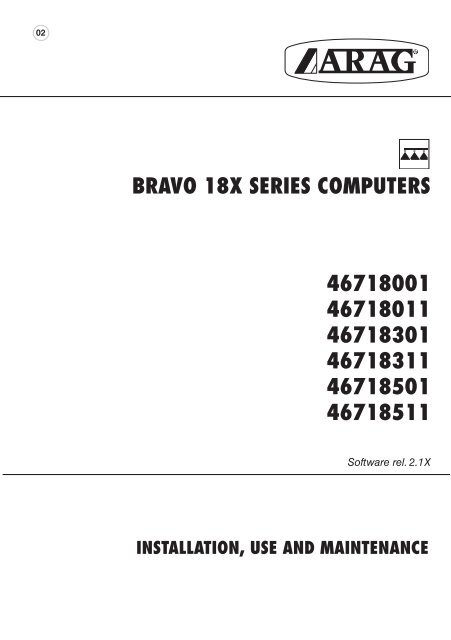
02BRAVO 18X SERIES COMPUTERS467<strong>180</strong>01467<strong>180</strong>1146718301467183114671850146718511Software rel. 2.1Xinstallation, USE and maintenance
• Legend symbols= Generic danger= WarningThis manual is an integral part of the equipment to which it refers and must accompany the equipment incase of sale or change of ownership. Keep it for future reference; <strong>ARAG</strong> reserves the right to modify thespecifications and instructions regarding the product at any time and without prior notice.
Contents• Legend symbols............................................................................................................................. 2• Foreword and use of this guide.................................................................................................. 5• Using the manual........................................................................................................................... 5• Limitations........................................................................................................................................ 5• Liability.............................................................................................................................................. 51 Product description....................................................................................................................... 62 <strong>Bravo</strong> DSB........................................................................................................................................ 63 Risks and precautions before assembly................................................................................. 64 Intended use.................................................................................................................................... 65 Contents of the package.............................................................................................................. 76 Location on the machine............................................................................................................. 86.1 Recommended system configuration................................................................................ 86.2 Locating the computer.......................................................................................................... 96.3 Mounting the bracket.......................................................................................................... 106.4 Location of the control unit................................................................................................ 107 Connecting the computer to the machine............................................................................. 107.1 General precautions for cable runs.................................................................................. 107.2 Power connection.................................................................................................................118 Connecting the cable to the control unit and services..................................................... 128.1 Connecting the multi-pin connector................................................................................. 128.2 Connecting the valves........................................................................................................ 128.3 Connecting the sensors and other services................................................................... 139 Accessory connections.............................................................................................................. 149.1 Foam marker........................................................................................................................ 1410 Computer controls and display................................................................................................ 1510.1 Control panel........................................................................................................................ 1510.2 Using the control keys........................................................................................................ 1510.3 Using the switches.............................................................................................................. 1610.4 Display (delivery)................................................................................................................. 1611 Preliminary programming.......................................................................................................... 1711.1 Pre-programming tests and checks.................................................................................. 1711.2 Switching on the computer................................................................................................ 1711.3 Switching on the computer for advanced programming............................................... 1811.4 Advanced menu................................................................................................................... 1811.5 Language.............................................................................................................................. 1911.6 Unit of measure................................................................................................................... 1911.7 Nr of sections....................................................................................................................... 1911.8 Total boom width................................................................................................................. 1911.9 Section................................................................................................................................. 2011.10 Section valve........................................................................................................................ 2011.11 Flowmeter............................................................................................................................. 2011.12 Tank volume......................................................................................................................... 2111.13 Tank reserve......................................................................................................................... 2111.14 Spraying menu..................................................................................................................... 21continues3
11.15 Pressure reckoning............................................................................................................. 2111.16 Nozzle number (only if "Pressure reckoning" = YES).................................................. 21USE................................................................................................................................................... 2212 User programming....................................................................................................................... 2212.1 Setting the dosage.............................................................................................................. 2212.2 Wheel constant setting....................................................................................................... 2312.2.1 Manual wheel constant setting......................................................................................... 2312.2.2 Automatic wheel constant setting..................................................................................... 2412.3 Selecting the wheel type (constant)................................................................................. 2612.4 Nozzle menu........................................................................................................................ 2712.5 Min. adjusting pressure...................................................................................................... 2713 Treatment........................................................................................................................................ 2813.1 Operating modes................................................................................................................. 2813.2 Field selection...................................................................................................................... 2913.3 Setting calibrated returns (control units with three-way valves).................................. 2913.4 Job/spray rate program selection (for automatic control ONLY)................................ 3013.5 Automatic treatment control............................................................................................... 3113.6 Manual treatment control................................................................................................... 3113.7 Distribution menu................................................................................................................ 3213.8 Fault warnings (for automatic control ONLY).................................................................. 3414 Maintenance / diagnostics / repairs........................................................................................ 3514.1 Troubleshooting................................................................................................................... 3514.2 Test menu............................................................................................................................. 3614.3 Problems due to the type of system and computer’s mode of operation..........................3814.4 Opening the connector and swapping the wires:........................................................... 3815 Technical data............................................................................................................................... 3915.1 Units of measurement........................................................................................................ 3915.2 Computer technical data.................................................................................................... 4116 Disposal at the end of service.................................................................................................. 4117 Guarantee terms........................................................................................................................... 424
• FOREWORD AND USE OF THIS GUIDEThis guide includes all instructions for correct assembly, connection and set up of BRAVO 18xfamily computers.Further informations are mentioned in special installer's sheets for each computer model.• Using the manualThis manual contains information reserved for the installation technician, and hence makes useof technical terminology without the explanations which would otherwise be required by the enduser.INSTALLATION IS TO BE DONE ONLY BY AUTHORISED AND TRAINED TECHNICALSTAFF.THE MANUFACTURER IS NOT LIABLE FOR USE OF THIS MANUAL BY UNAUTHORI-ZED AND UNQUALIFIED PERSONS.• LIMITATIONSAll assembly steps generally refer to a <strong>Bravo</strong> computer without mentioning any model, unless agiven installation procedure specifically concerns a certain model.• LiabilityThe installation technician is responsible for implementing the installation procedure in a professionalmanner so as to guarantee perfect functionality of the computer, whether supplied solely with <strong>ARAG</strong>components or with components from other manufacturers.<strong>ARAG</strong> recommends using its own components for the installation of the control systems.If the installation technician should decide to use components provided by other manufacturers,even if this should not require the modification of the cabling or other systems, he does so at hisown exclusive risk and liability.The installation technician is responsible for compatibility with components and accessories providedby other manufacturers.If, as a consequence of the above recommendations, the computer or other <strong>ARAG</strong> componentsinstalled in combination with components provided by other manufacturers should suffer damageof any kind, no form of liability, whether direct or indirect, will be recognized by <strong>ARAG</strong>.5
1 Product descriptionThe BRAVO 18x computer family includes spraying computers which control all aspects of productdistribution for agricultural applications.The computer enables the operator to control the valves and all treatment parameters, both inautomatic and manual mode.The computers are available in a range of configurations for different numbers of sections and forconnection to various types of sensor.The computer connects directly to the system thanks to a single cable connection to the control unitvalves and the sensors: the cab installation thus includes only the controls required for controllingthe system, giving total safety in operation.The BRAVO computer display enables the operator to monitor all the operational data, such as thespeed of the tractor, the amount of product being distributed, the total surface area treated, etc.2 <strong>Bravo</strong> DSB<strong>ARAG</strong> has designed and manufactured a diagnostics system for <strong>Bravo</strong> series computers and thesystems to which they may be connected.BRAVO DSB (article code 467003) provides reliable computer diagnostics (not of the control unitto which it is connected) so as to enable the resolution of any potential problems experienced withthe system.3 Risks and precautions before assemblyAll installation work must be done with the battery disconnected, using suitabletools and any individual protection equipment deemed necessary.Use ONLY clean water for treatment tests and simulations: using chemicalsduring simulated treatment runs can seriously injure persons in thevicinity.4 Intended useThe device you have purchased is a computer which, when connected to a suitable control unit,makes it possible to control all phases of treatment in agricultural applications directly from the cabof the agricultural machine in which it is installed.This device is designed to work on agricultural machinery for crop spraying applications.The machine is designed and built in compliance with EN ISO 14982 standard(Electromagnetic compatibility - Forestry and farming machines), harmonized with2004/108/EC Directives.6
5 Contents of the packageThe following table lists the components contained in the BRAVO computer package:BRAVO 18X SERIESTab. 1Legend:1 Computer2 Instruction booklets3 Inductive speed sensor4 Mounting kit5 Complete cabling for connection to the valves and sensors6 Gaskets for section valve connectors7 Power connector8 Power cable7
++6 Location on the machine6.1 Recommended system configurationAAssembly diagram for crop sprayers with membrane pumpBRAVO 18x MODE "M" (CODE 46718X11)B15/54+ -12VdcS1R2 345FG PLegenda:A Control panelB Starter keyS Speed sensorF Flow meterG Drain valveP Control valveR Foam marker1-5 Section valvesTab. 2AAssembly diagram for crop sprayers with membrane pumpBRAVO 18X MODE "P" (CODE 46718X01)B15/54+ -12VdcSR123 4 5F PGLegend:A Control panelB Starter keyS Speed sensorF Flow meterG Main valveP Control valveR Foam marker1-5 Section valvesTab. 3continues8
+Continues par. 6.1 - Recommended system configurationAssembly diagram for crop sprayers with centrifugal pumpBRAVO 18X MODE "M" (CODE 46718X11)AB15/54+ -12VdcSRLegend:123 4 5F PA Control panelB Starter keyS Speed sensorF Flow meterP Control valveR Foam marker1-5 Section valvesTab. 46.2 Locating the computerTab. 5 - 6BRAVO 18x series computers must be installed in the cab of the tractor, in observance of thefollowing precautions:- DO NOT install the computer in an area subject to excessive vibration or collisionsas this may damage it or lead to its controls being accidentally actuated;- install the unit is a visible position within easy reach by hand: bear in mind that thecomputer should not obstruct the operator’s freedom of movement or block his view.Note the connections required for the computer to operate (Tab. 5), the required lengthof the cables, and provide adequate space for the connectors and cable runs.An identification symbol is located next to each connector to indicate its function; forthe configuration of the systems, refer to par. 6.1 - Recommended system configuration.ITEMCABLE CONNECTIONPOINTSBRAVO 18x DIMENSIONSCod. Sections General Pressure Width A(mm)1 Control unit and Sensors 467<strong>180</strong>01 - 467<strong>180</strong>11 -- • • 1522 Power 46718301 - 46718311 3 • • 15246718501 - 46718511 5 • • 222Fig. 19
6.3 Mounting the bracketThe computer and control unit must be mounted on a bracket installed at the desired location(the previous paragraph shows the bracket drilling template).The bracket installs with the supplied bolts (A, fig. 2).Make sure the bracket is securely mounted, fit the computer to it and push it in until it locks in place(B, Fig. 2).Fig. 26.4 Location of the control unitThe control unit must be installed with the special brackets supplied and mounted to the unit, positioningit as shown in the manual provided with it.MAKE SURE TO FOLLOW ALL THE SAFETY INSTRUCTIONS GIVEN IN THE CON-TROL UNIT’S MANUAL.7 Connecting the computer to the machine7.1 General precautions for cable runs• Securing the cables:- secure the cables so that they do not interfere with moving parts;- route the cables in such a way that twisting and tractor movements cannot damage or breakthem.• Routing the cables to protect against water infiltrations:- branches in the cable runs must ALWAYS be oriented downwards (Fig. 3).Fig. 3 Fig. 4• Fitting the cables to the connection points.- Do not force the connectors by pushing too hard or bending them: the contacts can be damagedand computer operation compromised.• Use ONLY cables and accessories included in the part catalogue as they are technicallysuitable.10
7.2 Power connectionInside the package (component 7 - Tab. 1) you will find the power connector required for the connectionto the machine’s battery; Fig. 7 shows the drilling template for installing the power connector.Connect the power connector to the battery poles using two 6 mm faston connectors, as shownin Figs. 5 and 6.Use the cable provided in the package (component 8 - Tab. 1) to connect the computer to itspower supply.Fig. 5 Fig. 6 Fig. 7CAUTION: before powering up the computer and control unit, make sure the batteryvoltage is as specified (12 Vdc).The power supply can be connected to the unit in two ways:• direct connection beneath the key (15/54) as shown in Fig. 8.• connection via relay as shown in Fig. 9.If the 15/54 contact (services) of the starter key can bear a continuous load of 10A, install theconnections indicated in Fig. 8, with a 10A fuse on the power cable.Otherwise install a relay as indicated in Fig. 9 and install a 10 A fuse on the power cable.Direct connectionConnection via relayFig. 8Fig. 9CAUTION:• The power circuit must ALWAYS be fitted with a 10 Amp automotive fuse• All battery connections must be made with cables with a minimum cross section of2.5 mm 2To avoid short circuits, do not connect the power cable connector before the installationis completed.• Use cables with suitable terminals to ensure correct connection of each individualwire.11
8 Connecting the cable to the control unit and services• Use only the cables provided with the <strong>ARAG</strong> computer.• Take care not to break, pull, tear or cut the cables.• Use of unsuitable cables or cables not provided by <strong>ARAG</strong> automatically voids thewarranty.• <strong>ARAG</strong> is not liable for damage to the equipment, persons or animals caused byfailure to observe the above instructions.8.1 Connecting the multi-pin connectorConnect the multi-pin connector to the panel and connect the other end of its cable to the controlunit.Make sure that it is correctly fitted and turn the collar clockwise until it locks in place.8.2 Connecting the valves• All valve connectors must be equipped with gaskets before installation (Fig. 10).• Make sure the gaskets are correctly fitted to avoid infiltration of water when operatingthe control unit.Fit the connectors to the valves following the markings given in the general system installationdiagram in your possession (par. 6.1 - Recommended system configuration).Fig. 10• Remove the protector cap (1, Fig. 10) from the electrical valve.• Fit the gasket (2) onto the connector (3) and push the connector fully on (4): take care not tobend the valve’s electrical contacts.• Tighten screw (5) fully down.If the number of control panel switches is different from the number of section valves,connect the cables as shown in Tab. 7.Tab. 7COMPUTER N. SECTIONS SWITCHES CABLES46718301467183112 1 - 3 1 - 32 2 - 4 2 - 446718501467185113 2 - 3 - 4 2 - 3 - 44 1 - 2 - 4 - 5 1 - 2 - 4 - 512
8.3 Connecting the sensors and other servicesFit the connectors following the markings given in the general system installation diagram in yourpossession (par. 6.1 - Recommended system configuration).The cables are marked to indicate the service to which they connect (Tab. 8).Tab. 8ITEMCONNECTIONSSpeed sensorFFlow meterRFoam markerP Control valve / / Drain valveGMain valve1 ÷ 5 Section valvesUse <strong>ARAG</strong> sensors: use of unsuitable sensors or sensors not provided by <strong>ARAG</strong>automatically voids the warranty.<strong>ARAG</strong> is not liable for damage to the equipment, persons or animals caused by failureto observe the above instructions.- The speed sensor connection instructions are provided with the product.- Connect the flow meter and foam marker connector to the cable connector;check that it is inserted correctly and press it in until it locks.Fig. 11 Fig. 1213
9 Accessory connections9.1 Foam markerThe foam marker ONLY operates correctly if connected to the computer with the <strong>ARAG</strong> foam markercontrol kit, code 520004C.100.All information for connecting the foam markers is given in the manual provided with the device.Use ONLY the <strong>ARAG</strong> foam marker control kit: use of unsuitable kits or kits not providedby <strong>ARAG</strong> automatically voids the warranty in case of damage to the computer.• Positioning the foam marker control kitFig. 13- Position the control kit in a sheltered location, near tothe pump, with its cables exiting from its base.- Secure the device with the bolt provided in thepackage.CAUTION: if, due to limited space, thecable has to run around a corner, make surethat this is at least 5 cm away from the device,as shown in Fig. 13- Route the cables in such a way that they are longenough to reach the devices to which they are to beconnected.- Connect the cables as indicated in Fig. 14:R = BRAVO ComputerB = Power cableC = Foam marker- Secure the cables with clamps along their route.Fig. 1414
10 Computer controls and display10.1 Control panel- Computer spraying control keys.(par. 10.2 - Using the control keys)- Control unit valve switchesTab. 910.2 Using the control keysControl, selection and modification keysControl key:Resets the increment / decrement percentage of delivery value or sets its value.Control key:Activates the LH side foam marker.DOWN KEYData selection key:scrolls through the data fields in forwards order.Data modification key:decreases the value of the selected parameter.To change the value of the parameter more quickly, hold down the key for more than three secondsUP KEYData selection key:scrolls through the data fields in reverse order.Data modification key:increases the value of the selected parameter.To change the value of the parameter more quickly, hold down the key for more than three secondsConfirm key:confirms access to the selected menu or the modified parameter valueON/OFF buttonswitches the computer ON/OFF.ESC key:quits the current menu.Tab. 10If the modified data have not been confirmed, pressing ESC quits the menu without changing thevalues.Control key:Activates the RH side foam marker.Control key:Activates/deactivates automatic distribution control.15
10.3 Using the switchesControl unit valve switchesControl valve / drain valve switch (depending on system):Control valve:• to open the control valve, move the switch up (led on).• to close the control valve, move the switch down (led off).Drain valve:• to close the drain valve, move the switch up (led on).• to open the drain valve, move the switch down (led off).The references to the switch positions always as follows:• "ON" position: switch up• "OFF" position: switch downSection valve switches:normally each section valve installed on the unit has its own switch• To open the section valve, move the corresponding switch up (led on)• To close the section valve, move the corresponding switch down (led off)The section valve control depend on the type of operation enabled with the computer: for full details,refer to par. 13.1 - Operating modesControl valve switch:• to increase the amount of liquid to be delivered, move the switch upmanual operation: increases the amount of liquid to be delivered;automatic operation: increases the amount of liquid to be delivered in steps of 10% of theoriginal setting.• to decrease the amount of liquid to be delivered, move the switch downmanual operation: decreases the amount of liquid to be delivered;automatic operation: decreases the amount of liquid to be delivered in steps of 10% of theoriginal setting.Tab. 1110.4 Display (delivery)The main screen is described below: the symbols indicate the data which can be displayed duringtreatment.1 Distribution value data• A Increment / decrement percentage:indicates the percentage of the variation relative to the setdelivery value.• B Distribution value:the actual distribution value is displayed during treatment• C Spraying disabled: the main control switch is OFF.2 Foam marker active side• A LH side active• B RH side active3 Tank reserve status indicator:below the set "reserve" value, the computer generates avisual and audible warning.4 Control valve mode• A automatic• B manual5 Generic alarm symbol:refer to the paragraph dealing with common operatingfaults (13.8 - Fault warnings).6 Operating data:this field displays the treatment data (for example, thespeed); refer to par. 11.14 - Spraying menu.7 Speed simulator active:the tractor’s speed is not read by the sensor, but simulatedby the computer.The value is displayed to the right of the flashing icon.8 Other values: Number of the field being treated.Tab. 1216
11 Preliminary programmingThe computer can be programmed with the parameters required to ensure correct distribution ofthe treatment product.This must be done once only, when installing the computer.In the following paragraphs, the screen shots only show the key points of the programmingprocedure: the display may change when the keys described in the textare pressed.When setting parameters, their values flash on the display.11.1 Pre-programming tests and checksBefore programming the computer check that:• all components are correctly installed (control unit and sensors);• the equipment is connected to its power sources;• all components are correctly connected (control unit and sensors).Incorrect connections of the components and the use of other components fromthose specified can damage the system or components themselves.11.2 Switching on the computerSwitching ON (A + 1)Turn the ignition key to ON and press the button.The device runs a display self-test, displays thesoftware version, and then displays the deliverymenu.Switching the computer OFF (B)Press the button at any time until the screen beingdisplayed disappears.Release the button; the computer will switch offafter a few seconds.17
11.3 Switching on the computer for advanced programmingPower ON1) With the computer switched off, hold downthe keys together and press key 2; release key 2immediately after the device switches on.The device runs a display self-test, displays thesoftware version, and then displays the advancedmenu.11.4 Advanced menuThe advanced menu gives access to all BRAVO computer programming options.The minimum and maximum settable values for the parameters are given inparagraph 11.6 - Units of measurement.The following table shows the structure of the advanced menu.+PARAMETERSETTABLE DATAPar.Language 11.5Italian - English - SpanishPortuguese - French - GermanPolish - Russian - CroatianUnits 11.6EUUSUS TURFNo. of sections 11.7 1 ÷ 5Total boom width 11.8Section valves 11.10Section(submenu - par. 11.9)2-Ways3-WaysFlowmeter 11.11 ValueTank volume 11.12 ValueTank reserve 11.13 ValueSpraying menu 11.14Pressure reckoning 11.15LargeShortYESNONozzle number 11.16 1 ÷ 1000ValueTab. 13(Menu item "Nozzle number" is active) ONLY if the previous item is set to "YES"(Pressure reckoning).18
11.5 LanguageThis parameter sets the computer’s display language.Available languages are the following: Italian, English, Spanish, Portuguese, French, German,Polish, Russian, Croatian.11.6 Unit of measureThis parameter sets the units used to display data on the computer.• EU = European units• US = USA units• US TURF = USA units (applied volume = gal / 1000 square feet)For the list of displayable data and units of measurement, refer to paragraph15.1 - Units of measurement.11.7 Nr of sectionsThis parameter sets the number of section valves present on the control unit.CAUTION: For computers code 467<strong>180</strong>01 and 467<strong>180</strong>11 set this value to 1.11.8 Total boom width• Technical headings1 A• Section width(section valve A)1 B• Section width(section valve B)2• Boom widthTab. 14continues19
Continues 11.8 - Total boom widthThis parameter represents the effective spray coverage achieved by the nozzles: for example,if there are 3 nozzles spaced 50 cm apart, the boom section width will be 1,5 m.The displayed value represents the sum of the section widths.To modify the data, set the value for each individual boom section: the sum of the widths isautomatically recalculated.11.9 SectionBoom section settingsTotal boom width1+ 1+21) Use the keys to scroll through the parameters in theAdvanced Menu and selectTotal boom width, followed by its value: thisvalue is calculated by the computer from the widthsof each section, which can be set in the Sectionsubmenu. The Total boom width parameter isthe sum of the individual section lengths.2) Press the key to open the submenu to select/modifythe individual sections.Section3+ 3+43) Use the keys to scroll through the sections in theSection submenu until the section you wish tomodify is displayed: the sections are displayed at thetop right of the display, while the line below displays thecurrent value.4) Press the key to confirm that you wish to modify thevalue.5) Modify the section width with the keys: to change thevalue more quickly, hold the keys down.Section11.10 Section valve5+ 5+A6BDuring data modification:A) Press the key to confirm the new value.B) Press the key once to exit without modifying thevalue.6) Press the key to return to theTotal boom widht parameter.During data modification a flashing cursorwill be displayed.This parameter sets the type of section valves present on the control unit:• 2-way (valves without calibrated return)• 3-way (valves with calibrated return)11.11 FlowmeterThis parameter sets the flowmeter constant: this indicates how many flowmeter pulses correspondto one unit of liquid delivered.This constant is indicated on your flowmeter’s data plate; for ORION flowmeters only,refer to the "Technical data" section in the flowmeter’s user manual for the value tobe entered in the computer.20
IMPORTANT:BRAVO 18x computers can only calculate the flow and delivery rates correctly if theflow meter has been installed to the control unit and the flow meter constant hasbeen set.11.12 Tank volumeThis parameter sets the amount of liquid which can be contained by the tank: this is thus the maximumamount to which the tank can be filled.11.13 Tank reserveThis parameter sets the "reserve" value, below which the computer generates a visual and audiblewarning: when the reserve value is reached during operation, the tank symbol (Fig. 15) on thedisplay flashes.The sound alarm stops when the tank is completely empty.Fig. 1511.14 Spraying menuDuring distribution, you can display and control the treatment data in real time.The BRAVO 18x computer can display the data in an extended or reduced menu.Table 15 gives the displays in both modes.DATUM LARGE SHORTSpeed • •Pressure * • •Flow rate • •Area • •Sprayed quantity • •Treated field • •Tank levelTimeDistance•••Tab. 15* Only if "Pressure reckoning" in Advanced menu is set to YES.11.15 Pressure reckoningThis parameter allows the display of a pressure value as reckoned depending on flow rateat the nozzle and shown by the flow meter in the "Distribution menu".11.16 Nozzle number (only if "Pressure reckoning" = YES)This parameter allows to set the total number of bar nozzles.This setting allows <strong>Bravo</strong> <strong>180</strong> to reckon system pressure according to the flow rate shownby the flow meter.21
• USEThis section of the manual explains how to use the BRAVO 18x computer.The keys and their descriptions are given in Chapter 10 - Computer controls and display.12 User programmingBefore starting a treatment, a number of settings are required to ensure that the treatment isimplemented correctly.Once the data have been entered, treatment can be started.The screenshots in the following paragraphs cover only the main settings:the display may change when the keys specified in the text are operated.Access to User menu1) Hold down the key for one second.---- Menu ------- User ---âRates setupDisplays the main Menu Userscreen.The computer now enables you to setthe treatment dosage values.12.1 Setting the dosageThe BRAVO 18x is able to store up to 5 dosage settings:1) Press to confirm access to the dosage settingsmenu.RateAB3 3 2 45Keys A and B scroll through the five settings or,when the cursor flashes, modify the value.2) Press to enter dosage value modification mode.The selected value flashes.3) Press to increase/decrease the value.4) Confirm the setting.5) Press to exit from the menu.22
Nozzle type to be matched with spray rate can be selected only if pressure reckoning isENABLED:Rate 1/5USER1When "Pressure reckoning" is ENABLED,nozzle type and spray rate will alternativelyflash in the lower display line.Press OK to select one of the two items.Press UP and DOWN keys to set asrequired. Press OK to confirm and goto next item, or press ESC to quitwithout saving.If the use of customizable nozzles is required (USER1 to USER5), they can be selected withoutchanging their settings. To change their settings, go to Advanced menu.12.2 Wheel constant settingThe wheel constant is the distance traveled by the tractor per speed sensor pulse. This value is usedby the BRAVO 18x to calculate the tractor’s speed and hence the dosage at a given speed.The wheel constant depends on the type of wheel and the number of sensing points installed on it.The BRAVO 18x can store up to 3 different wheel constants.If the wheel on which the speed sensor sensing points are installed is changed, thewheel constant may change.At this point the value must be reset.12.2.1 Manual wheel constant settingThe wheel constant can be calculated to a good approximation by measuring the distance traveledby the wheel on which the speed sensor is installed. The longer the distance traveled, the moreprecisely the wheel constant can be determined.We recommend making the measurement with the tires inflated to their operatingpressure.The wheel constant (WheelK) is calculated as follows:WheelK =distance traveled (cm)nr. sensing points x nr. wheel rotationswhere: is the distance in cm traveled by the wheel during the measurement, is the number of sensing points (e.g. magnets, bolts, etc.) on the wheel, is the number of rotations of the wheel over the measured distance.Continues23
Wheel constant calculation example:the calculation supposes that the wheel has effected 20 rotations (over a measured distance of7536 cm). The wheel has 8 sensing points.WheelK =75368 x 20WheelK = 47,10This is the value to be entered in the BRAVO 18x.1) Press to confirm modification of the wheel constant.2) Press to confirm the modification of the value, indicatedat the top right of the display.Press A to select the wheel constant for the nextwheel.3) The BRAVO 18x prompts for manual setting of thewheel constant: press to modify the value.Press A to set the wheel constant automatically(par. 12.2.2).4) Press to modify the value.5) Confirm the new value.6) Press twice to exit from the menu.12.2.2 Automatic wheel constant settingThe BRAVO 18x is able to calculate the wheel constant automatically from the number of pulsesreceived from the speed sensor while traveling over a straight line path of:• 100 m (EU)• 300 feet (US - US TURF)The setting procedure must be done on medium hard ground.If treatment is to be done on soft or very hard terrain, the changed rolling diametercan result in errors in delivery calculation: in this case we recommend running theprocedure again.Automatic wheel constant setting is done by traveling over the measured distance with the tankfilled only with water, to half of its total capacity.24
1) When the menuRates setup displays, select theWheels setup menu2) Press to confirm modification of the wheel constant3) Press to confirm the modification of the value, indicatedat the top right of the display.Press A to select the wheel constantfor the next wheel.4) The BRAVO 18x prompts for manual setting ofthe wheel constant: press to set the wheel constantautomatically.Wheel constantManual setup4Wheel constantAutomatic calc.5) Press to confirm: the display will prompt for you tostart the tractor.Drive the measured distance: the number of pulses willincrease.At the end of the measured distance, stop the tractor.6) Press to terminate the procedure.The computer will display the number of cm(inches) traveled per pulse.The wheel constant is now stored.7) Press twice to return to the distribution menu.If the display reads Error!, this means that the number of pulses received by thecomputer during the automatic calibration procedure is too low to calculate thewheel constant; this can be due to incorrect mounting of the wheel or if the sensoris located too far away from the sensing points. Check that the sensor is correctlymounted and repeat the procedure.If the problem persists, contact the installation technician.25
12.3 Selecting the wheel type (constant)Once the wheel constants have been stored (up to 3), they can be called up as required for thewheels in use.1) When the Rates setup menu displays,press twice to access the Wheel Selectionmenu.The menu will ONLY display if at least two wheelconstants are stored in the computer.2) Press to confirm access.3) Press to select the desired "wheel type" (wheel constant).4) Confirm the selection.5) Press to return to the Menu Spraying.Only the types of wheels will display for which wheelconstants have been stored in the computer.26
12.4 Nozzle menuThis menu allows to set selected nozzles.Nozzle data0,40 l/min.11) When displaying Nozzle data , menu, the followingparameters will alternatively flash in the lower line:- Flow rate (e.g. ).- Pressure (e.g. ).Press OK to enter the submenu.2) Press UP and DOWN to display ISO nozzles and all5 customizable nozzles (USER 1 to 5).ISO110010,40 l/min.3) Press OK to enter submenu to set all parameters ofUSER nozzles only.USER11.37 l/min.4) Press UP and DOWN to switch from FLOW RATE toPRESSURE: press OK to set the required parameter.USER1Flow rate5) Press UP and DOWN to set the required value(flashing item) and then press OK to confirm and UPand DOWN to switch to other item to be set followingthe same procedure.Flow rate1.37 l/min.12.5 Min. adjusting pressureThis menu allows to set a pressure value under which <strong>Bravo</strong> <strong>180</strong> disables automatic adjustingfunction.This menu item is displayed only if "Pressure reckoning" in Advanced menuis set to YES.27
13 TreatmentOnce the preliminary configurations described above have been completed, it is possible to startthe treatment in MANUAL or AUTOMATIC mode.In the following paragraphs, the screen shots only show the key points of the settingprocedure: the display may change when the keys described in the text are pressed.13.1 Operating modes• Operating mode "P":the section valves are controlled independently.Operating the main control switch does not affect the status (open or closed) of the sectionvalves.• Operating mode "M":the section valves are opened and closed with the main control switch*, so long as the section valveswitch is appropriately positioned; in other words, if the section valve switches are set to OFF (leverdown), operating the main control switch will not affect the section valves. If one or more sectionvalve switches are set to ON (lever up), closing or opening the main control switch will close andopen the respective section valves as well.* operation of the main control switch is described in par. 10.3 - Using the switchesTab. 16BRAVO CODE Sections General Pressure Mode "P" Mode "M"467<strong>180</strong>01•• •467<strong>180</strong>11 •46718301•3 • •46718311 •46718501•5 • •46718511 •28
13.2 Field selectionWhen treating a field, the BRAVO 18x collects the data for the current job (treated surface, liquiddelivered, treatment time, distance traveled) and stores up to 4 different treatments.These data can be called up with the "FIELD" function.300 l/haFig. 16300 l/haFig. 17Select the field before starting a new treatment: if this is not done, the data will beadded to those for the last selected field.13.3 Setting calibrated returns (control units with three-way valves)Calibrated returns, fitted onto control units with three-way valves, ensure there are no pressurevariations when closing one or more section valves.Set EACH TIME nozzle type is changed.Please refer to user's guide supplied with purchased control unit for details onadjusting procedure.If nozzle type is not changed, adjustments made ensure a steady spray even in case of jobsat different operating pressure.29
13.4 Job/spray rate program selection (for automatic control ONLY)Before starting treatment, select the right dosage from those provided in the Menu User (par. 12.1).300 l/ha9.1 Km/h 1) Hold down the key for 1 second toenter the dosage selection menu.12) Press to scroll through the dosagesettings.3) Confirm the selection.If pressure reckoning is ENABLED on spray rate selection,pressure reckoning value and selected nozzle will alternately flash on the display.Rate30
13.5 Automatic treatment controlRefer to Chapter 10 - Computer controls and display - for information on operatingthe keys and switches.300 l/ha 1) Press to enable automatic mode: the letter "A"(automatic) displays.12) Open the section valves by setting the control panelswitches to the up position: their leds will turn on*.3) Drive to the start of the field.4) Set the main control switch up: its led will turn on.6) Run the treatment.*: the leds only turn on for computers configured to operate inP mode. If the computer is configured for M mode, the sectionleds will only turn on when the main control switch is set to ON.4 2When treatment is run in automatic mode, thecomputer keeps delivery to the set value: press thepressure control valve switch to temporarily changethe distribution value: the value can be modified in10% steps (in the range -50% - +50%).This temporarily changes the distribution value:to set a new permanent distribution value, refer topar. 12.1 - Setting the dosage.A) Press to increase the distribution value.B) Press to decrease the distribution value.Attention: when the distribution value is beingchanged, the display alternately flashes the variationpercentage and the current distribution value.To return to the set distribution value, press theRATE key.13.6 Manual treatment controlRefer to Chapter 10 - Computer controls and display - for information on operatingthe keys and switches.300 l/haM11) Press to enable manual mode: the letter "M"(manual) displays.2) Open the section valves by setting the controlpanel switches to the up position: their ledswill turn on*.3) Drive to the start of the field.4) Set the main control switch up: its led will turn on.5) Operate the switch to set the desired dosage.6) Run the treatment.4 25*: the leds only turn on for computers configured to operatein P mode. If the computer is configured for M mode, thesection leds will only turn on when the main control switchis set to ON.31
13.7 Distribution menuThis menu provides the treatment options. Almost all parameters have a submenu which can beaccessed by holding down the UP and DOWN keys together for 1 second; this opens the functionassociated with the selected menu.In all submenus, pressing OK confirms entry or modification of a parameter, while pressing ESCcancels the operation or quits the menu option.Measuring the current speed300 l/haSpeedSpeed simul.?YESNOSimulating the tractor’s speed enablesproduct distribution even without aspeed sensor mounted to the wheels.The default simulation setting is 6 kph;this can be changed by holding downOK and pressing the UP and DOWNkeys.When this function is used, thedosage cannot be the real valueinasmuch as the speed of the tractoris not detected in real time.Instantaneous pressure indication300 l/haPressureTHIS ITEM WILL SHOW ONLYIF PRESSURE RECKONING ISENABLEDThis function allows the user to readpressure value proportional to flow rateand selected nozzle.Instantaneous flow rate indication300 l/haFlow rateTreated surface count300 l/haAreaReset?This function resets the treated surfacecount for the field indicated at the rightcorner of the display.YESNOCONTINUES32
Liquid distributed count300 l/haSprayed qty.Reset?This function resets the liquid distributedcount for the field indicated at the rightcorner of the display.YESNOField treated300 l/haFieldField selectionPress to select the field to be treated.After the field selection has beenconfirmed, the computer will prompt forthe operator to reset the parameters forthe selected field.Reset?Field dataTank level*300 l/haTank levelTank fillingThis function fills the tank.The computer displays the maximumfilling value, which can be changed withthe UP and DOWN keys.Confirm by pressing OK.Treatment time*300 l/haTimeReset?Press to reset the treatment timecounter for the field at the right cornerof the display.Confirm with OK, cancel with ESC.YESNODistance traveled count*DistanceReset?Press to reset the distance traveledcount for the displayed field. Confirmwith OK, cancel with ESC.YESNOTo return to the speed display, hold down the UP key for three seconds at any time.* this menu option is only displayed if EXTENDED menu mode is selected.33
13.8 Fault warnings (for automatic control ONLY)If distribution errors occur during treatment, the computer warns the operator by sounding a buzzerand displaying a message describing the problem.Speed alarmThe computer does not detect the tractor speedand the control unit is supplied (control valve openor drain valve closed).Set the main control switch to OFF or startthe tractor.If the tractor is already in motion, there may bea problem with the speed sensor.12Flow rate alarmIf there is insufficient flow to the flow meter andhence to the control unit, the computer notifiesthe user (1) by display 0 flow rate (2).Distribution alarmIf the set distribution value cannot be reached,the computer indicates that the tractor shouldspeed up or slow down.Tab. 1734
14 Maintenance / diagnostics / repairs14.1 TroubleshootingFAULT CAUSE REMEDY• Turn the ignition key to "Ignition".The display does not turn on No power• Check the power cable connections.• Press the power button.The valves do not respondto controlsThe valves are not connected • Connect the connectors.A valve refuses to open No power to valve• Check the electrical connection and functionalityof the valve.The displayed speed is Incorrect programming • Check the wheel constant setting (par. 12.2).incorrect even at constant Speed sensor signal not received • Check the speed sensor connection.speedIncorrect speed sensor installation • Check the speed sensor installation.• Check the boom width setting (par. 11.8).• Check the flow meter constant settingThe delivery volume display(par. 11.11).Incorrect programmingis incorrect• Check the speed sensor installation.• Check the wheel constant setting (par. 12.2).• Check the section valve type setting (par. 11.10).The treated surface countdisplayed on the computerdiffers from the actualamount of terrain coveredThe traveled distance countdisplayed on the computerdiffers from the actualdistance traveledThe delivered liquid displaydiffers from the actualamount of liquid deliveredThe set distribution valuecannot be obtained duringautomatic operationThe time count displaydiffers from the actualtreatment timeTab. 18Incorrect programmingThe counter has not been resetIncorrect programmingThe counter has not been resetIncorrect programmingYou are using 3 way section valvesand the calibrated returns have notbeen calibratedThe counter has not been resetIncorrect programmingThe system cannot deliver therequested flow rateControl valve malfunctionThe counter has not been reset• Check the boom width setting (par. 11.8).• Check the speed sensor installation.• Check the wheel constant setting (par. 12.2).• Reset the counter.• Check the speed sensor installation.• Check the wheel constant setting (par. 12.2).• Reset the counter.• Check the flow meter constant setting (par. 11.11).• Check the section valve type setting (par. 11.10).• Calibrate the returns.• Reset the counter.• Correct the distribution value.• Correct the boom width.• Check the setting of the maximum pressurevalve.• Check that the installed control valve is correctfor the system in use.• Check the functionality of the control valve.• Reset the counter.35
14.2 Test menuThis menu tests that the computer is operating correctly.To access the menu, turn the computer on with the AUTO and RATE keys held down.All tests are READ ONLY; the parameters cannot be modified.Display testTractor battery voltage testSwitches testOperate the switches to test that they are working correctly.M Control valve / drain valve switch (depending on system)1÷5 Section valve switches(the computer will display the actual number of sections installed)+ / - Control valve switchCONTINUES36
Speed sensor input testThe frequency reading in Hz of the speed sensor displays.Flow meter input testThe frequency reading in Hz of the flow meter displays.Keyboard testPress the keys to display the respective text.Key texts:RATE: RATE KEYLH foam marker: TFSX KEYOK: OK KEYRH foam marker: TFDX KEYAUTO: AUTO KEYThe UP, DOWN and ESC keys cannot be tested.37
14.3 Problems due to the type of system and computer’s mode of operationAll work intended to partially or completely modify the operation of the computer orany components connected thereto is done at the user’s full and exclusive liability.If there is any doubt regarding alternative computer cable hookups, please contactyour nearest service center for further information.IMPORTANT: FOLLOW INSTRUCTIONS BELOW ONLY IF PERFECTLY SURE THEYWILL GRANT CORRECT SYSTEM OPERATION.Inverse operation of the pressure regulation may be caused by the type of control unit and systemto which it is connected. Resolve the problem as described in the following table; if the problempersists, contact your local service center.Machine with centrifugal pumpLegend:F Flow meterP Control valve1-5 Section valves123 4 5FPSwap wires 1 and 2 in the controlvalve connectorTab. 1914.4 Opening the connector and swapping the wires:Fig. 18 Fig. 19 Fig. 20• Unscrew the cable clamp with a small pair of pliers (Fig. 18).• Prize the connector open with a screwdriver in the provided slot (Fig. 19).• Slacken off the screws and swap the wires (Fig. 20).Tighten the screws to the correct amount when securing the cables.38
15 Technical data15.1 Units of measurement• Advanced menuDatum Min. Max. UM Description NotesLanguage -- -- --Units of measurement-- -- --DisplaylanguageUnits of measurementused todisplay dataLanguage options:Italian, English, French, German, Spanish,Portuguese, Polish, Russian, Croatian.Available options:EU, US, US TURFNumber ofsections-- -- --Number of sectionvalves installedAvailable options:1 ÷ 5Width ofeach individualsectionSectionvalves0,00 29,99 EU: m0,0 299,9US - US TURF:feet-- -- --Flow meter 1 29999Tank capacity1 19999Tank reserve 0 19999Type ofdisplay of thedistributionmenu-- -- --EU: imp/lUS - US TURF:imp/galEU: lUS - US TURF:galEU: lUS - US TURF:galBoom width(each section)Type of sectionvalveFlow meterconstantTank capacityTank reserve valueDetermines whetherthe counters aredisplayed or notTo display this valueset the width of each boom sectionAvailable options:2 way valve - without calibrated return3 way valve - with calibrated returnUsed for calculating the flow rateBelow this value, the computer generatesa visual and audible warningAvailable options:Large, ShortPressurereckoningYES NO --Enable/disablepressure reckoningNozzlenumber*1 1000 --Number of barnozzlesTab. 20*= only if the previous item is set to "YES" (Pressure reckoning).39
Delivery valuesDatum Min. Max. UM Description Notes0 1990 EU: l/haLiquid deliveredVolumeDisplays on the first line of the display0,0 199,9 US: gpa per unit surfaceappliedduring treatment0,0 199,9 US TURF: gpkarea0 199,9 EU: km/hVehicle’s speed ofSpeedUS - US TURF:0 199,9travelmphPressure0,0 999,9EU - EU-l/100m:barDistributionpressure0 9999 US: psiFlow rate0 999,9 EU: l/minLiquid deliveredUS - US TURF:0 999,9per unit timegal/min0 19999 EU: l Level of liquidTank levelUS - US TURF: remaining in the0 19999galtankField -- -- --Number of the fieldbeing treatedTab. 21Delivery countersAvailable only if "Pressure reckoning" inAdvanced menu is set to YES.Liquid actually delivered by the nozzlesFloating decimal pointThe counter decreases when the maincontrol switch is set to ONUp to 4 values can be setDatum Min. Max. UM Description Notes0,000 99999 EU: haSurface 0,000 99999 US: acresFloating decimal pointTreated surface The counter increases when the main controlareaUS TURF:0,000 99999switch is set to ON1000 square ftLiquiddelivered0 99999 EU: l0 99999US - US TURF:galLiquid deliveredThe counter increases when the main controlswitch is set to ONTime 0:01 99999DistanceTab. 22EU - USUS TURF: h0,001 99999 EU: km0,001 99999US - US TURF:milesTime of operationDistance traveledFloating decimal pointThe counter increases when the main controlswitch is set to ONFrom 00:01 to 99:59 in hh:mm formatFloating decimal pointThe counter increases when the main controlswitch is set to OFF40
User menuDatum Min. Max. UM Description NotesDosage0 600 EU: l/ha0 600,0 US: gpa0 60,00 US TURF: gpkDesired distributionrate--Setdosages1 5 --Number of settabledosagesUp to 5 values can be set;zero settings are not displayedWheelconstant0 99,99 EU: cm/imp*0 99,99US - US TURF:inch/imp*Wheel constantsettingUsed to calculate the tractor speed;zero settings are not displayedWheelsettings1 3 --Number of settablewheelsNozzlesettings # ISO11001 USER5 --Min.adjustingpressure #Tab. 23Disabled*imp= pulse100.0 bar(1450 psi)Selected nozzletypeMin. pressure fordisabling automaticadjusting function#= only if “Pressure reckoning” = YES17 available nozzles: 12 ISO steadynozzles and 5 customizable nozzles15.2 Computer technical dataTab. 24DescriptionDisplay:Power supply:Consumption (only computer):Working temperature:Digital inputs:Weight:Protection against reversal of polarity:Protection against short circuit:BRAVO 18xAlphanumeric LCD display2 lines x 16 characters, backlit11 ÷ 14 Vdc150 mA0°C ÷ 60 °C+32°F ÷ +140 °Ffor open collector sensors: max. 2000 imp./s726 g(<strong>Bravo</strong> code 46718501 without cabling)••16 Disposal at the end of serviceDispose of the system in compliance with the established legislation in the country of use.41
17 Guarantee terms1. <strong>ARAG</strong> s.r.l. guarantees this apparatus for a period of 360 day (1 year) from the date of saleto the client user (date of the goods delivery note). The components of the apparatus, thatin the unappealable opinion of <strong>ARAG</strong> are faulty due to an original defect in the material orproduction process, will be repaired or replaced free of charge at the nearest AssistanceCentre operating at the moment the request for intervention is made.The following costs are excluded:- disassembly and reassembly of the apparatus from the original system;- transport of the apparatus to the Assistance Centre.2. The following are not covered by the guarantee:- damage caused by transport (scratches, dints and similar);- damage due to incorrect installation or to faults originating from insufficient or inadequatecharacteristics of the electrical system, or to alterations resulting from environmental,climatic or other conditions;- damage due to the use of unsuitable chemical products, for spraying, watering, weedkillingor any other crop treatment, that may damage the apparatus;- malfunctioning caused by negligence, mishandling, lack of know how, repairs or modificationscarried out by unauthorised personnel;- incorrect installation and regulation;- damage or malfunction caused by the lack of ordinary maintenance, such as cleaning offilters, nozzles, etc.;- anything that can be considered to be normal wear and tear.3. Repairing the apparatus will be carried out within time limits compatible with the organisationalneeds of the Assistance Centre.No guarantee conditions will be recognised for those units or components that have notbeen previously washed and cleaned to remove residue of the products used;4. Repairs carried out under guarantee are guaranteed for one year (360 days) from thereplacement or repair date.5. <strong>ARAG</strong> will not recognise any further expressed or intended guarantees, apart from thoselisted here.No representative or retailer is authorised to take on any other responsibility relative to<strong>ARAG</strong> products.The period of the guarantees recognised by law, including the commercial guarantees andallowances for special purposes are limited, in length of time, to the validities given here. Inno case will <strong>ARAG</strong> recognise loss of profits, either direct, indirect, special or subsequent toany damage.6. The parts replaced under guarantee remain the property of <strong>ARAG</strong>.7. All safety information present in the sales documents regarding limits in use, performanceand product characteristics must be transferred to the end user as a responsibility of thepurchaser.8. Any controversy must be presented to the Reggio Emilia Law Court.42
Conformity Declaration<strong>ARAG</strong> s.r.l.Via Palladio, 5/A42048 Rubiera (RE) - ItalyP.IVA 0<strong>180</strong>1480359Dichiarache il prodottodescrizione: Computermodello: <strong>Bravo</strong> <strong>180</strong>serie: 46718xxx e 467110Wrisponde ai requisiti di conformità contemplati nelle seguenti Direttive Europee:2004/108/CE e successive modificazioni(Compatibilità Elettromagnetica)Riferimento alla Norma Applicata:EN ISO 14982:1998(Macchine agricole e forestali – Compatibilità elettromagneticaMetodi di prova e criteri di accettazione)Rubiera, 21 Dicembre 2007Giovanni Montorsi(Presidente)
Only use original <strong>ARAG</strong> accessories and spare parts, to maintain safety conditions foreseen by the constructor.Always refer to the <strong>ARAG</strong> spare parts catalogue.D20127_GB-m04 12/201042048 RUBIERA (Reggio Emilia) ITALYVia Palladio, 5/ATel. 0522.622011Fax 0522.628944info@aragnet.comhttp://www.aragnet.com