grimpeur 2500 - 3000 mc - Bargam UK
grimpeur 2500 - 3000 mc - Bargam UK
grimpeur 2500 - 3000 mc - Bargam UK
- No tags were found...

You also want an ePaper? Increase the reach of your titles
YUMPU automatically turns print PDFs into web optimized ePapers that Google loves.
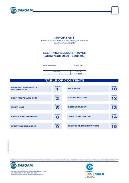
IMPORTANTKeep this service manual to hand during the machine/equipment's working lifeSELF-PROPELLED SPRAYER(GRIMPEUR <strong>2500</strong> - <strong>3000</strong> MC)user manualENGLISHSerial numberEdition 012-2005TABLE OF CONTENTSGENERAL AND SAFETYINFORMATIONBooklet1KIT AIR UNITBooklet10SELF-PROPELLED UNITBooklet2BALANCING UNITBooklet12MIXER UNITBooklet5COMPUTER UNITBooklet13SHOCK ABSORBER UNITBooklet8LITRE COUNTER UNITBooklet14SPRAYING BOOM UNITBooklet9TECHNICAL MODIFICATIONSBooklet15IDMCO368137021300.fmAll rights reserved. No part of this service manual may be reproduced without written authorisation from the manufacturer. Our company has an on-going policy of improvement and this manual may be updated without prior notice being issued as long as there is nosafety risk involved. © 2003 - IDM esperti in comunicazione tecnica - Forlì - Author of the text, illustrations and page layout. This text is registered as IDM's intellectual property and may be partially or entirely reproduced with acknowledgements to the author.via della Cooperazione, 20 - 40026 IMOLA (BO) - ITALYtel.+390542648511 - fax +390542640539 -www.bargam.com - e-mail: salesimola@bargam.com
Booklet1GENERAL ANDSAFETY INFORMATIONuser manualSerial number Edition 212-2005TABLE OF CONTENTSCComposition of the manual and method of reference, 2DDocumentation enclosed, 3MManual, composition, method of reference, 2Manual, purpose, 2Manufacturer and equipment, identification, 3Manufacturer and machine identification and equipment, 3PPurpose of the manual, 2SSafety and information markings, 5Safety regulations, 3Service procedure, 3IDM332113010101.fmEnglish- 1 -
General and safety informationBooklet 1PURPOSE OF THE MANUALThis manual has been written by the manufacturer andconstitutes an integral part of this machine. Theinformation contained in this manual is intended forpersons who are qualified to operate the machine andtrained to use it during its expected lifetime.In addition to adopting good use techniques, therecipients must carefully read and strictly apply thisinformation. This information has been produced bythe manufacturer in his own original language (Italian)and can be translated into other languages to satisfylegal and/or commercial requirements.Time dedicated to reading this information will avoidpersonal safety, health risks and economic damages.Should this manual contain additional informationcompared to the actual parts of the machine, this willnot interfere with the reading thereof.Keep this manual for the entire life of the machine in aneasily accessible place for quick reference whenevernecessary.Some of the pictures and pieces of information in thismanual may not correspond perfectly to what youhave. This does not however hinder operation.As the manufacturer is carrying out a policy of continuousproduct development and updating, he reservesthe right to alter this document without theobligation of prior notice.To better stress the importance of some passages orto indicate important specifics, symbols, whose meaningsare described as follows, have been adopted.Warning - CautionIndicates critically dangerous situations that, if neglected,can result in serious personal safety andhealth hazards.Danger - AttentionIndicates that suitable actions must be employedin order to avoid personal safety, health hazardsand economic damages.ImportantIndicates particularly important technical informationthat should not be neglected.COMPOSITION OF THE MANUAL AND METHOD OF REFERENCE332113010101.fmIDMThis instruction manual, barring anydifferences which do not affect thecorrectness of the information,consists only of the leaflets concerningthe machine in question and theoperating units which make it up.The illustration below shows the manuallayout.A) Cover page: indicates the modeland the description of the machineincluding publishing and IDinformation.It also contains the list of leafletsrelative to the components whichcan be installed. Some of these components maybe missing from this machine.B) Leaflet 1 - General safety information: containsthe information necessary to identify the machine,use the manual as well as all the informationregarding safety.C) Leaflet 2 - General description of the machine:contains the basic principles as well as themanufacturing and operating philosophies.D) Leaflets 3, 4, 5, 6..... - Information on theoperating units installed: they contain all theABCinformation relative to each unit installed on themachine.E) Last leaflet - Technical modifications: it containsany information on the modifications made to themanual over time.ImportantRead this leaflet before the others since it containsmore recent information compared to the manualherein.EDIDM-3320000040.tifEnglish- 2 -
General and safety informationBooklet 1332113010101.fmIDMNever tamper, dodge, eliminate or by-pass the safetydevices installed on the machine. Neglect to respectthis requirement may cause serious risk to personalsafety and health.The staff in charge of carrying out any work on themachine during its entire life must have specialtechnical knowledge, particular skills and certifiedexperience in the specific sector. Neglect to observethese requirements may prove hazardous to personalsafety and health.Only wear and use the protective clothing and/ordevices indicated in the instructions provided by themanufacturer or work safety laws in force whenoperating the machine.Some phases may require the help of one or moreassistants. In these cases such persons should besuitably trained and informed on the type of activitybeing performed, so as not to cause damage to thehealth and safety of persons.Handling and loading specificationsHandling and loading must be carried out as per theinstructions on the packaging, on the equipment itselfand in the manufacturer's handbook.Handling, loading and unloading must be carried outby trained personnel with specific competence in thisfield. During manoeuvres while using the equipmentthe driver must be familiar with the proceduresnecessary to carry out these operations safely.The equipment may only be loaded onto andtransported by hoisting devices having sufficientcarrying capacity, anchored at the points specified bythe manufacturer.All moving and lifting operations must be carried out incompliance with the information supplied on thepackaging, on the machine and in the instructions foruse supplied by the manufacturer.The staff in charge of loading, unloading and movingthe machine must have skills and certified experiencein the specific sector. During manoeuvres, when usingthe machine directly, the operator must know theprocedures required to carry out these operations insafe conditions.Lifting and transportation must be carried out usingsuitable means and anchoring the machine in theplaces provided by the manufacturer. Personnel whoare authorised to perform these operations mustpossess specific skills and experience, to safeguardthemselves and others involved.Before moving the machine with vehicles, make surethat the machine and its components are suitablyanchored to the vehicle and that their volume does notexceed the maximum allowable values. Place therequired signals if necessary.It may be necessary to move the machine frequently.To avoid sudden, uncontrolled movement make surethat all parts which could cause this have been safelylocked before transportation.Approved equipment may be driven on public roads bya licensed driver. In any case, before startingtransportation, block the parts which could causesudden unexpected movements and check that thevolume does not exceed the maximum allowablevalues. If necessary, arrange proper signalling.Operation and use regulationsApart from being appropriately informed on the use of themachine, the operator must have the necessary skillsand knowledge to carry out the specific type work.Even after having been adequately trained on machineuse, perform trial manoeuvres to familiarise theoperator with machine controls and functions, start upand arrest in particular, on first use if necessary.Only use the machine for the purposes expresslyintended by the manufacturer. The improper use of themachine could place the personal safety and health ofthe staff at risk as well as cause economic damage.The machine has been designed and constructed tosatisfy all the operating conditions indicated by themanufacturer. Tampering with any device to achieveservices other than those provided may be hazardous topersonal safety and health and provoke economic loss.Do not use the machine if the safety devices are notperfectly installed or in perfect operating condition.Failure to comply with this requirement could place thepersonal safety and health of people at risk.During the preparation and use of all chemicals,appropriate measures must be taken in order to avoidplacing people’s health and safety at risk and harmingthe environment.All residual chemical substances must be disposed ofproperly according to local laws and regulations. Avoidpolluting the environment.Park the machine in an appropriate area where it doesnot create any obstacle or danger to circulation. Turnthe engine off and take adequate precautions toprevent unauthorised personnel from accessing thedriving seat.Do not allow unauthorised people to get close to theoperating area when the machine is being used. Ifnecessary cease operations immediately and have thearea at risk cleared.English- 4 -
General and safety informationBooklet 1Caution - danger to body: do notgo near the moving components.Lifting point: indicates the liftingcylinder inserition points.Caution: skidding andoverturning risk: disable theoperating control and that of the“four steering wheels” beforebeginning the road circulation.Danger: Hot surfaces: be carefulof hot surfaces.Danger of impact: be careful ofprotruding parts.Prohibited use: do not spray waterunder pressure to avoid damagingparts.Mandatory use of fresh water:wash your hands after each contactwith the chemicals used.Mask must be worn: to protectthe respiratory tract when handlingand using chemicals.Boots must be worn: to protectfeet and legs when handling andusing chemicals.Clean water must be used: to fillup the clean water tank.Mandatory reading of the Usermanual. The person in charge ofthe equipment operation shall readthe manual in order to know theposition and the function of controlsas well as to familiarize withall information contained. Alwayskeep the document within reach.Gloves must be worn: to protecthands from abrasions.No access to unauthorisedpeople: do not stand in or walkthrough the machine’s operatingrange.Grip points: indicates the manualgrip points.Protective clothing must beworn: to protect the body whenhandling and using chemicals.Height adjustment signal: thisindicates the height adjustmentpoints when using a lifting hook.Protective gear must be worn:protective earmuffs must be wornwhile operating the machine.Emergency exit: marks theemergency exit.IDM332113010101.fmEnglish- 6 -
Self-propelled for spraying (GRIMPEUR <strong>2500</strong> - <strong>3000</strong> MC)Booklet 2A332100021200.fmIDMShock absorber adjustment (with a manualpump), 21Shock absorber adjustment (with themachine's hydraulic system), 22Shock absorber check (with a manualpump), 42Shock absorber check (with the machine'shydraulic system), 44Shock absorber system, 49Shock absorbers (with a manual pump),adjustment, 21Shock absorbers (with a manual pump),check, 42Shock absorbers (with the machine'shydraulic system), adjustment, 22Shock absorbers (with the machine'shydraulic system), check, 44Shock absorbers, adjustment, 20Special maintenance, 54Spraying boom, hydraulic systemdiagram, 70Spraying pump and centrifugal pump,systems, 50Steering column electrical systemdiagram, 88TTable of maintenance work, 38Technical specifications, 5Tool kit, 10Towing the machine, 14Track adjustment, 16Track configuration, 15Tracks, adjustment, 16Tracks, configuration, 15Transportation, 11Transportation, lifting, 11Troubles, causes, remedies, 55Tyre replacement, 58Tyre table, 6UUse and operation, instructions for, 24Use of systems, 54Use, first, 40Use, recommendations for, 36VVibration level, 6WWater tank filter replacement, 62Windshield wiper fluid level check, 47Wiring diagram for analog steering card, 90Wiring diagram for differential gearlocking, 92Wiring diagram for push-button panel, 78Wiring diagram for push-button panelextension, 80Wiring diagram for steering line, 91Wiring diagram of cabin line, 84Wiring diagram of the boom control, 102123456789101112131415161718192021222324252627282930313233343536373839404142434445English- 2 -
Self-propelled for spraying (GRIMPEUR <strong>2500</strong> - <strong>3000</strong> MC)Booklet 2A1234567891011121314151617181920212223242526272829303132333435363738394041424344454647484950515253332100021200.fmIDMTECHNICAL INFORMATIONGENERAL DESCRIPTION OF THE MACHINEThe sprayer, hereinafter referred to as the machine,has been designed and built for agricultural use and,more precisely, for spraying medium to large surfaceareas. It can be used to spray chemicals (such asfertilisers, herbicides and pesticides) over the field ordirectly onto the crops.Only one operator is required aboard. The operatorRNPBQUSFMain componentsA) Tank; for the product to be sprayedB) Clean water tank; to clean the systemC) Cab (ROPS); for the operator’s seat. It is fitted withall the controls and accessories (windshield wipers,rear-view mirrors, lights, etc.), is soundproof, withanti-glare glass, air conditioning and an active coalfilterD) Row marker foam tank; to distribute the foamwhich marks the perimeter of the sprayed areaE) Clean water tank; for washing handsF) Oil tank; to activate the hydraulic devicesG) Endothermic engine; to supply power to the maincomponentsH) Hose winder; to fill the tank, complete with hoseL) Diesel fuel tank; for the engine fuelM) Mixer; to mix the liquid for sprayingN) Spraying bar; to spray the mixed productYWVmust be properly trained to drive and operate themachine safely.In order to protect the operator against contaminationrisks and to ensure appropriate operating conditions,the machine has been fitted with a soundproof cab withan active carbon filter.The machine is approved for use on public roads.CGIDM-33210000100.tifP) Water distribution unit (sectional valves); toselect the spraying sectors of the barQ) Pump; to pressurise the product to be sprayedR) Centrifugal pump; to fill the tank with waterS) Battery; to power the electrical systemT) Water cocks; to select filling, mixing, spraying andcleaningU) General distribution unit; to open and close thesupply to the water distribution unit (P)V) Pressure gauge; to measure the pressure of theservice water system. Should the central sprayingsystem be retracted or in the event of a pressuregauge (W) malfunction, it measures the indicativebar supply pressureW) Pressure gauge; to measure the bar operatingpressureY) Tank; to store the oil for the pedal service brakeAELDHTMEnglish- 3 -
Self-propelled for spraying (GRIMPEUR <strong>2500</strong> - <strong>3000</strong> MC)Booklet 2A332100021200.fmIDMGENERAL DESCRIPTION OF THE CABThe diagram shows the main components.A) Seat; for the operator to sit on. It is adjustable, toensure the appropriate ergonomic conditions (seepage 18)B) Steering wheel and controls; adjustable toprovide the appropriate ergonomic conditions forthe operator (see page 18)C) Cab controls; to enable the service devices andinterior cab light (see page 32)D) Controls for use and forward motion; to enable allthe operating functions of the machine (see page 30)GIMPROPER USE– Any use of this machine for purposes other thanagricultural ends cannot be deemed to comply withthe manufacturer’s instructions; the manufacturer isconsequently relieved of any liability for damagescaused by such a use, and the operator shall alsobe fully liable towards any third parties involved.– Before operating the machine, it is vital that youcheck carefully for the presence of any overheadelectrical wires which the bars may interfere with,placing the operator’s safety at risk.BE) Computer; to programme and manage thespraying functions. It is connected to a sensor (G)which measures the sprayer’s forward speed, inaccordance with which the computer regulates theflow of the product that needs to be sprayed (seeleaflet 13)F) Windshield wiper fluid tank; to store thewindshield wiper detergentH) Glove compartment– Road circulation is allowed for authorised machines.Operators must comply with the requirements setforth by the laws in force. In any case, beforestarting transportation, block the parts which couldcause sudden unexpected movements and checkthat the volume does not exceed the maximumallowable values. If necessary, arrange propersignalling.CEDAFHIDM-33210000200.tif123456789101112131415161718192021222324252627282930313233343536373839404142434445English- 4 -
Self-propelled for spraying (GRIMPEUR <strong>2500</strong> - <strong>3000</strong> MC)Booklet 2A1234567891011121314151617181920212223242526272829303132333435363738394041424344454647484950515253332100021200.fmIDMTECHNICAL SPECIFICATIONSEngine 129 kW (175 HP)Brand....................................................IVECO - AIFOType ........................................................F4GE0684CCylinders ...................................................................6Total CCs .................................................... 6700 cm 3Maximum capacity ...................... 129 kW a 2400 rpmCooling system.................................................. WaterTransmission........................................... hydrostaticHydrostatic pump ........ SAUER-DANFOSS 90R100Hydrostatic motor ........SAUER-DANFOSS 51D110-1Wheel flanges (front and rear): they allow to modifythe track, according to their assembly.Steering– wheel with power steering system Sauer-DanfossOSPC 160LS for two or four wheelsEmergency parking brake: oil-bath multidisk withelectrohydraulic command on the front wheelsService brake: oil-bath multidisk on the four wheelswith foot commandTurning radiusEnglish8 (1) m(1) With 1800 mm track (A)4,5 mIDM-33311009100.tifSizeA.........................6,80 m (7,40 m with air-assisted kit)B..................................... 2,50 m (3,00 m with bar P5)C.......................................................................1,65 mD.........................1,85 m (2,45 m with air-assisted kit)E.......................................................................3,40 mF .......................................................................3,30 m- 5 -IDM-33210000400.tifWeight <strong>2500</strong> MC: during operation and with operatoraboard; values refer to machine fitted with the largesttyresOverall weight...................(empty) 6100 (full) 8600 KgFront axle .........................(empty) 3300 (full) 4200 KgBack axle..........................(empty) 2800 (full) 4400 KgWeight <strong>3000</strong> MC: during operation and with operatoraboard; values refer to machine fitted with the largesttyresOverall weight...................(empty) 6100 (full) 9100 KgFront axle .........................(empty) 3300 (full) 4300 KgBack axle..........................(empty) 2800 (full) 4800 KgNote: The weight of the machine equipped with theair-assisted kit should be increased by 200 kg.Hydraulic systemDiesel fuel tank.....................................................230 lHydraulic oil tank ..................................................165 lWater pumphydraulic motor ............ SAUER-DANFOSS OMS-125Self-priming pumphydraulic motor ....................... CASAPPA PLM 20.25Water systemTank ....................................................... <strong>2500</strong> - <strong>3000</strong> lCleaning water tank..............................................275 lHand-washing tank.................................................17 lElectrical systemNormal voltage ................................................. 12 VoltAlternator: n.1 ................................................... 120 ABattery: n.1..........................................12 Volt 140 Ah
Self-propelled for spraying (GRIMPEUR <strong>2500</strong> - <strong>3000</strong> MC)Booklet 2A332100021200.fmIDMTYRE TABLEGRIMPEUR<strong>2500</strong>MC - <strong>3000</strong>MCTyres600/65 R28(ømm 1491x591)710/55 R30(ømm 1232x630)600/60 - 30.5(ømm 1495x600)800/45 - 30.5(ømm 1500x800)540/65 R34(ømm 1566x550)270/95 R38(ømm 1468x290)420/85 R38(ømm 1675x429)540/65 R38(ømm 1675x550)270/95 R42(ømm 1565x284)300/95 R42(ømm 1617x316)270/95 R44(ømm 1625x270)300/95 R46(ømm 1724x309)270/95 R48(ømm 1710x284)NOISE LEVELThe table shows the noise levels according tooperating conditions and measurement points.With engine atmaximum rpmVIBRATION LEVELMax allowable loadand speedIn the operating process, the machine has differentvibration levels, as indicated in the table.PressureThe measurements have been calculated by followingthe ISO 2631/1 standards.TransferMax speedWorkTrack(G)Minimumheight fromthe ground(H)Kg Km/h bar Km/h Km/h m. cm30753780365044903420420040855024290035602300283025753167308037902430299027253350<strong>2500</strong>307530803790265032604020402040204020402040204020402040204020402040204020LAcq - dB(A)Operator’s seat 79,3Noise pollution 112,5Measuring pointBody, head,arms and handsVibration level(m/s2)Highestacceptable value(m/s2)0,46 0,51,6 21 - 34 5 - 9 2,25 611,6 22 - 35 6 - 9 2,35 612,2 22 - 35 6 - 9 2,25 641,5 21 - 34 6 - 9 2,35 611,4 23 - 37 6 - 10 2,20 633,6 21 - 34 6 - 9 1,80 - 2,00 - 2,25 621,6 24 - 39 6 - 10 2,05 701,4 24 - 39 6 - 10 2,20 683,6 23 - 36 6 - 10 1,80 - 2,00 - 2,25 673,6 24 - 38 6 - 10 1,80 - 2,00 - 2,25 703,6 24 - 38 6 - 10 1,80 - 2,00 - 2,25 703,6 25 - 40 7 - 11 1,80 - 2,00 - 2,25 743,6 25 - 40 7 - 11 1,80 - 2,00 - 2,25 75123456789101112131415161718192021222324252627282930313233343536373839404142434445English- 6 -
Self-propelled for spraying (GRIMPEUR <strong>2500</strong> - <strong>3000</strong> MC)Booklet 2A1234567891011121314151617181920212223242526272829303132333435363738394041424344454647484950515253332100021200.fmIDMALLOWABLE SLOPESThe figure illustrates the maximum allowable slope onnon-yielding, non-sagging land with the machine inDANGER ZONEThe figure illustrates the danger zones where no-oneshould be when the machine is in use. It is theoperator’s duty to keep such zones out of bounds; ifnecessary, (s)he should turn the engine off and clearout the danger zone.operation and fully loaded.IDM-33210000500.tifIDM-33210000600.tifEnglish- 7 -
Self-propelled for spraying (GRIMPEUR <strong>2500</strong> - <strong>3000</strong> MC)Booklet 2A332100021200.fmIDMSAFETY DEVICESThe figure illustrates the position of the safety deviceson the machine.A) Battery connector; to disconnect the batteriesfrom the electrical circuit. The batteries must bedisconnected during all maintenance operations.After disabling the ignition key, turn the key towardsthe left and remove it from its housing.B) “Product distribution to bar exclusion” switch;to exclude the bar distribution controls, especiallyduring transfer with closed barsC) “Operating controls exclusion” switch; toenable and disable the operating controlsD) “Rear steering exclusion” switch; to enable anddisable the rear steeringCaution - PrecautionThe "4 wheel drive" operation can be selected onlywhen in first gear and with the 4 wheels aligned.Danger - WarningDisable the “operating control” (C) and that of the“rear steering exclusion” (D) before beginning theroad circulation.MFAE) Emergency exit; To get out of the machine in theevent of an emergency. Use the hammer (L) tobreak glassF) Acoustic signal; to warn staff members near themachine that it is reversing or that bar movementsare under wayG) Tank level sensors; to prevent the machine frombeing put into faster gears when there is water inthe tank (max. 20 km/h)H) Spraying bar arm support; to secure the closedbar in order to avoid any sudden extension of thearms during road circulationL) Hammer; use to crash glass in an emergency.M) Shut-off valve; hydraulic device to block liftingdevice during maintenance.N) Seat beltCaution - PrecautionCheck every day that the safety devices areinstalled and function properly.EGGLN123456789101112131415161718192021222324252627282930313233343536373839404142434445HDCBIDM-33210000700.tifEnglish- 8 -
Self-propelled for spraying (GRIMPEUR <strong>2500</strong> - <strong>3000</strong> MC)Booklet 2A1234567891011121314151617181920212223242526272829303132333435363738394041424344454647484950515253332100021200.fmIDMPOSITION OF PLATESThe figure shows the location of all safety plates, whiletheir meaning is explained in booklet 1.ImportantMake sure the plates are completely legible; if thisis not the case, replace them and reposition themin their original place.IDM-33210000800.tifEnglish- 9 -
Self-propelled for spraying (GRIMPEUR <strong>2500</strong> - <strong>3000</strong> MC)Booklet 2A332100021200.fmIDMPOSITION OF IDENTIFICATION PLATESThe figure shows the position of theidentification plates.DEVICES FOR ROAD CIRCULATIONThe machine is provided with all thedevices for road circulation incompliance with the regulations inforce.The figure shows the position of thesafety devices.A) Flashing lightB) Rear-view mirrorsC) Front direction indicator lightsD) Front lightsE) Rear lights (position lights, directionindicator lights, brake lights)F) Rear reflectorsG) Licence plate lightH) front overall lightsL) Maximum allowable speed panel(homologation)M) Refractive panelN) rear overall lightsTOOL KITThe following tools are supplied standard with themachine:– 1 set of 6÷32 ordinary spanners– 2 screwdrivers– 1 set of pliers– 1 hydrostatic transmission pump filter (see page 48)– 1 oil tank filter (see page 62)– 2 hydraulic system filters (see page 62)– 1 foaming agent container 2,5 lBHHDAIDM-33210001000.tif– 2 complete jets– 2 flexible hoses for shock absorber adjustment– 2 ø 1/4”; flexible hoses for shock absorberadjustment and machine lifting– no. 1 cable joystick to adjust suspensions and to liftthe machine– 1 "Kit Air Assisted" pump filterNCHIDM-33210000900.tifMLNFGE123456789101112131415161718192021222324252627282930313233343536373839404142434445English- 10 -
Self-propelled for spraying (GRIMPEUR <strong>2500</strong> - <strong>3000</strong> MC)Booklet 2A1234567891011121314151617181920212223242526272829303132333435363738394041424344454647484950515253332100021200.fmIDMINFORMATION ABOUT HANDLING AND INSTALLATIONINSTRUCTIONS FOR HANDLING AND LOADINGImportantAll handling and loading operations must becarried out in compliance with the informationsupplied on the packaging, on the machine and inthe instructions for use supplied by themanufacturer.TRANSPORTATIONBased on the destination, the machinecan be transported in different ways.The diagram shows the mostcommonly used solutions.During transportation, if the machineexceeds the allowable overalldimensions, reduce them as indicatedon page 12.ImportantTransport the machine with thespraying product and water tanksempty.LIFTING FOR TRANSPORTATIONThe machine can be lifted using a hooktruck featuring a suitable load bearingcapacity, with the hooks inserted in thepurpose-provided areas on themachine.When transporting in open topcontainers, if the maximum heightallowed is exceeded disassemble theboom side arms - see boom usermanual.ImportantThe lifting devices are not providedwith the equipment.If necessary, the person in charge of these operationsmust organise a “safety plan” to guarantee thepersonal safety of the operators.IDM-33205108900.tifIDM-33210001300.tifEnglish- 11 -
Self-propelled for spraying (GRIMPEUR <strong>2500</strong> - <strong>3000</strong> MC)Booklet 2A332100021200.fmIDMROAD TRANSPORTATION LOADImportantThe machine must be transportedwith a lowboy.Load the machine as indicated below.1 -Disassemble the lateral arms ofthe bar (see instruction manual ofthe bar) if the bar exceeds 2,55 min width.2 -Seal the fittings of anydisconnected hoses with caps toavoid leaks.3 -Load the machine onto the vehiclemanoeuvring it from the operator's seat.4 -Activate the parking brake.ImportantThe staff in charge of loading, unloading andmoving the machine must have skills andIf the maximum height allowed isexceeded, disassemble the wheels asdescribed below.5 -Lift the equipment (see "Lifting fortransportation") and place it onsupports (A).IDM-33210001400.tifexperience acquired in the specific sector. Duringmanoeuvres, when using the machine directly, theoperator must be informed on the proceduresrequired to carry out these operations safely.support (A)IDM-33210001500.tif123456789101112131415161718192021222324252627282930313233343536373839404142434445English- 12 -
Self-propelled for spraying (GRIMPEUR <strong>2500</strong> - <strong>3000</strong> MC)Booklet 2A1234567891011121314151617181920212223242526272829303132333435363738394041424344454647484950515253332100021200.fmIDM6 -Disassemble the wheels byunscrewing the fixing nuts (B).7 -Lift the equipment (see "Lifting fortransportation") and place it on thevehicle.8 -Secure the machine and thedisassembled components to thevehicle using ropes and wedges(as shown in the figure).ImportantSecure the ropes to the main frameof the machine.nut (B)IDM-33210001600.tifIDM-33210001700.tifEnglish- 13 -
Self-propelled for spraying (GRIMPEUR <strong>2500</strong> - <strong>3000</strong> MC)Booklet 2A332100021200.fmIDMTOWING THE MACHINEImportantThe machine can only be towed forshort distances at a speed of nomore than 1 km/h. When towing iscomplete, restore the initialconditions.For this operation follow the procedurebelow.ImportantHook the machine onto a tow truckfeaturing a suitable load bearingcapacity and appropriate dimensions.1 -Attach the machine to the tow truck with rigid bars(A) using the purpose provided attachments.2 -Uncouple pipes (B). Avoid oilwaste in the environment.3 -Carefully plug each male andfemale coupling to keep it cleanand to protect threading.Note: if the diesel engine doesnot start, unloosen counter-nut(D) and loosen screw (E) tounlock the negative parkingbrake of the front axle.4 -Use knob (C) to put in neutral.5 -Tow the machine with the operatorin the driver’s seat.6 -Once trailed, return to the initialcondition.bars (A)ImportantWhen towing with the machine engine off, thenegative brake should be released.IDM-33210001900.tifknob (C)lock nut (D)IDM-33210001800.tiftubes (B)screw (E)123456789101112131415161718192021222324252627282930313233343536373839404142434445English- 14 -
Self-propelled for spraying (GRIMPEUR <strong>2500</strong> - <strong>3000</strong> MC)Booklet 2A1234567891011121314151617181920212223242526272829303132333435363738394041424344454647484950515253332100021200.fmIDMINFORMATION ABOUT ADJUSTMENTSINSTRUCTIONS FOR ADJUSTMENTSImportantBefore carrying out any setting or adjustment,activate all the safety devices required andconsider whether it may be necessary to provideproper information to the operators and to the staffworking near the machine. In particular, provideTRACK CONFIGURATIONDifferent track configurations can be obtainedaccording to the work distance and type of tyre.Diagram for 1800 - 2000 - 2250 trackTyres270/95 R48270/95 R44270/95 R38270/95 R42230/95 R44300/95 R46340/95 R36300/95 R42Tyres540/65 R34540/65 R38800/45 30.5proper signs in the areas surrounding the machineand do not allow anyone to access any devicesthat, when activated, may cause unexpecteddangerous conditions, resulting in damages topersonal safety and health.The diagrams illustrate the various combinationspossible, also depending on the type of mount.IDM-36810002000.tifEnglish- 15 -
Self-propelled for spraying (GRIMPEUR <strong>2500</strong> - <strong>3000</strong> MC)Booklet 2A332100021200.fmIDMTRACK ADJUSTMENTImportantAdjust with the engine on at 1000 revs/min andwith the machine standing on level and compactMake the adjustment one wheel at atime.For this operation follow the procedurebelow.1 -Pull out the pivot (A) and the splitpin (B) to disassemble the cylinder(C).2 -Insert the cylinder (C) in thehousing provided to lift the axlewhich needs to be adjusted.3 -Insert a support plate (D) toguarantee a surface which is largeenough to support the liftingcylinder (C).4 -Disconnect hoses (H) for laddercontrol.5 -Connect the hoses (E) on thelifting cylinder (C) and on thepoints of attachment on themachine.lifting cylinder (C)ground to guarantee the stability of the liftingdevices.lifting cylinder (C)split pin (B)pivot (A)lifting cylinder (C)supportplate (D)IDM-36810002100.tifIDM-36809004100.tifhoses(E)123456789101112131415161718192021222324252627282930313233343536373839404142434445hoses(H)IDM-36810002200.tifEnglish- 16 -
Self-propelled for spraying (GRIMPEUR <strong>2500</strong> - <strong>3000</strong> MC)Booklet 2A1234567891011121314151617181920212223242526272829303132333435363738394041424344454647484950515253332100021200.fmIDM6 -Insert the plug (F) to enable thecontrol electrically (G).7 -Use switch (R) to lift the wheelabove the ground.8 -Insert the support (L) to ensurethat the wheel remains off theground.9 -Loosen the wheel fastening nuts(M) to remove the wheel and rotatethe flange.10 -Put the wheel back on and secureit with the nuts.11 -Use switch (R),to lift the axle andremove the support (L).12 -Use switch (R), until the machinehas been lowered completely.IDM-33211002300.tifplug (F)control (G)switch (R)support (L)nut (M)IDM-36809004200.tifIDM-33210001600.tifEnglish- 17 -
Self-propelled for spraying (GRIMPEUR <strong>2500</strong> - <strong>3000</strong> MC)Booklet 2A332100021200.fmIDM13 -Close the lifting cylindercompletely (C) and remove it fromthe support once the operation hasbeen completed.14 -Repeat the above operations tomake the adjustments on the otherwheels.15 -When the adjustments arecomplete, disconnect the hoses(E) and disassemble the liftingcylinder (C). Reposition it in thehousings provided when theoperation is complete.OPERATOR'S SEAT ADJUSTMENTThe steering wheel and the seat maybe adjusted by the operator to obtainsuitable ergonomic conditions.ImportantAdjustments must be made whenthe machine is not in motion.Steering wheel adjustmentLoosen the lever (A), tilt the steeringwheel to the desired position andsecure it with the lever (A).Seat adjustmentTo adjust the seat, refer to the figureswith the various positions.lever (A)lifting cylinder (C)hoses (E)IDM-36809004200.tifIDM-33211002600.tif123456789101112131415161718192021222324252627282930313233343536373839404142434445English- 18 -
Self-propelled for spraying (GRIMPEUR <strong>2500</strong> - <strong>3000</strong> MC)Booklet 2A1234567891011121314151617181920212223242526272829303132333435363738394041424344454647484950515253332100021200.fmIDMManual adjustment seatIDM-33211009500.tifEnglish- 19 -
Self-propelled for spraying (GRIMPEUR <strong>2500</strong> - <strong>3000</strong> MC)Booklet 2A332100021200.fmIDMPneumatically-adjustable seat (the control panelmust be switched on for this operation).SHOCK ABSORBER ADJUSTMENTOn delivery, the machine shock absorbers may beempty. Before operating the machine, refill the shockabsorbers. This can be done in two different ways:– with a manual pump (see page 21).– with connection to the machine’s hydraulic system(with the engine on) (see page 22).IDM-33211009400.tifDanger - WarningAll maintenance must be carried out by speciallytrainedstaff in workshops which are adequatelyequipped.123456789101112131415161718192021222324252627282930313233343536373839404142434445English- 20 -
Self-propelled for spraying (GRIMPEUR <strong>2500</strong> - <strong>3000</strong> MC)Booklet 2A1234567891011121314151617181920212223242526272829303132333435363738394041424344454647484950515253332100021200.fmIDMSHOCK ABSORBER ADJUSTMENT (WITH A MANUAL PUMP)Front shock absorbersImportantCarry out this operation with anempty tank and with the sprayingbar retracted.For this operation follow the procedurebelow.1 -Connect the manual pump to thepressure taps (A) using thecapillary hoses provided.Caution - PrecautionScrew the capillary hosessimultaneously to the pressuretaps (A) to avoid any oil leaks.2 -Inject hydraulic oil until thecylinders (B) are in the maximumextension position.3 -Drain the oil from the pump untilthe cylinders (B) get 70 mm lower.4 -Disconnect the hoses and thepump when the operation iscomplete.socket (A)socket (A)manual pumpmanual pumpcylinder (B)cylinder (B)IDM-36810002400.tifIDM-3681000<strong>2500</strong>.tifEnglish- 21 -
Self-propelled for spraying (GRIMPEUR <strong>2500</strong> - <strong>3000</strong> MC)Booklet 2A332100021200.fmIDMSHOCK ABSORBER ADJUSTMENT (WITH THE MACHINE'S HYDRAULIC SYSTEM)Front shock absorbersImportantCarry out this operation with anempty tank and with the sprayingbar retracted.For this operation follow the procedurebelow.1 -Connect the hose (A) provided tothe fast attachment (B), replacingthe hose for the movement of thestep ladder.2 -Connect the hose (A) to thepressure tap (C) using the capillaryhoses provided.Caution - PrecautionScrew the capillary hosessimultaneously to the pressure taps(C) to avoid any oil leaks.3 -Connect the plug (D).4 -Use switch (G), to inject hydraulicoil until the cylinders (F) are in themaximum extension position.socket (C)cylinders (F)plug (D)switch (G)attachment(B)hose (A)IDM-36810002600.tifIDM-36810002700.tif123456789101112131415161718192021222324252627282930313233343536373839404142434445English- 22 -
Self-propelled for spraying (GRIMPEUR <strong>2500</strong> - <strong>3000</strong> MC)Booklet 2A1234567891011121314151617181920212223242526272829303132333435363738394041424344454647484950515253332100021200.fmIDM5 -Use switch (G), to drain hydraulicoil until the cylinders (F) are 70 mmlower.6 -Disable and disconnect the hosesand the plug of the push-buttonpanel once the operation has beencompleted.AIR CONDITIONING COMPRESSOR BELT ADJUSTMENTTurn the screw (A) to adjust thetension of the belt.ImportantCheck the tension as indicated inthe figure. The resulting value (R)must be 10÷15 mm.switch (G)IDM-33210002900.tifscrew (A)cylinder (F)IDM-36810002800.tifEnglish- 23 -
Self-propelled for spraying (GRIMPEUR <strong>2500</strong> - <strong>3000</strong> MC)Booklet 2A332100021200.fmIDMUSER INFORMATIONINSTRUCTIONS FOR USE AND OPERATIONImportantThe incidence of accidents related to the use of themachine depends on multiple factors that are notalways easy to prevent and control. Some accidentsmay depend on unforeseeable environmental factors;others are caused by the behaviours of the staff usingthe machine. Apart from being authorised andproperly informed, if necessary, when using themachine for the first time, operators must simulatesome manoeuvres in order to get familiar withcontrols and main functions. Use the machineDESCRIPTION OF CONTROLSAll the controls used to operate and transfer themachine are located near the operator’s seat in thecab. Below are the symbols, the position and thefunction of the controls.CONTROL PANEL1exclusively for the purpose intended by themanufacturer. Do not tamper with any device to obtaina different performance. Before using the machine,make sure that the safety devices are correctlyinstalled and in perfect working conditions. Apartfrom complying with these requirements, operatorsmust apply all safety regulations in force and carefullyread the description of the various controls and theinstructions on how to operate the machine.ImportantSome button controls have a safety device forpreventing accidental operation. This safetydevice should be unlocked before using buttons.Pos Symb. Name Function Symb. Indication13112B304APedal button for water systemdistribution unit control.1617232521352622411133235 3643 44Activates the water system.Note: it is also connected to thesteering system to commutate thefour wheel drive to two wheel driveduring the work phase .1815221920144137 4038 67 392742333481092829Press to activate.Press again to deactivateIDM-33210003200.tif123456789101112131415161718192021222324252627282930313233343536373839404142434445English- 24 -
Self-propelled for spraying (GRIMPEUR <strong>2500</strong> - <strong>3000</strong> MC)Booklet 2A1234567891011121314151617181920212223242526272829303132333435363738394041424344454647484950515253332100021200.fmIDMPos Symb. Name Function Symb. IndicationPush the lever to accelerate.Pull the lever to decelerate.2 Accelerator lever Accelerates the engine3Spraying bar hydraulic controlsand machine handling lever.The information on the variousfunctions can be found beneaththe heading “Forward motion andbrake lever”.4 Fuse box (no. 2). Contains the fuses567Yellow water system indicatorlight.Water system pump controlswitch.Steering lever control switch (A)(see page 28).8 Front suspension locking switch9 Work control switch10 Parking brake control switch1112Mechanical speed gearboxswitchSteering activatingfoot-control buttonIndicates the activation of thewater system pump.Activates the water systempump.To activate the functions of thelever (A).Note: the fast gears cannot beused with the lever (A)activated.To lock the suspensions on thefront axleActivates and deactivates thework controlsActivates and deactivates theparking brakeTo select the slow or fastmechanical gearTo activate the four wheel driveduring the work phase.13 Ladder switch. To open and close the ladder.14Yellow water pump indicatorlight.Indicates the lack of oil in thespraying pump or the breakageof the diaphragms.ImportantThe seat is provided with asensor that detects thedriver’s presence. Theaccelerator lever is activeonly when the driver is sittingon his/her seat.On: pump activated.Off: pump deactivated.Use to activate or deactivate thepump.Release the safety catch andactivate the lever functions.ImportantDeactivate the control beforeroad circulation begins.Use it to lock and unlock thesuspensions on the front axleRelease the safety catch andactivate or deactivate the controls.ImportantDeactivate the control beforeroad circulation begins.Release the safety catch andactivate or deactivate the brake.Unlock the safety and engagethe creep mechanical gearUnlock the safety device andengage the fast mechanicalgearImportantUse the switch only when themachine is not operatingUse to activate or deactivate thefunctionUse to open and close theladder.On:– oil level insufficient– diaphragms brokenOff:– oil level ok– diaphragms intact.English- 25 -
Self-propelled for spraying (GRIMPEUR <strong>2500</strong> - <strong>3000</strong> MC)Booklet 2A332100021200.fmIDM115 Green direction indicator light.16 Blue high-beam indicator light.17 Red alternator indicator light.181920212223243112B304ARed engine oil pressureindicator light.Yellow engine preheatingindicator light.Red parking brake indicatorlight.Red hydraulic oil level indicatorlight.Red cooling liquid temperatureindicator light.Green position lights indicatorlightMechanical gear orange pilotlamp161723252135262Pos Symb. Name Function Symb. Indication241113Indicates that the directionindicator lights are onIndicates that the high beamsare on.Indicates the alternatoroperation status.Indicates the condition of theengine oil pressure.Indicates the preheating phaseof the spark plugsIndicates the activation of theparking brake.Indicates the oil level (it iscombined with the acousticsignal (B)).Indicates the temperature of theliquid.Indicates that the position lightsare on.It signals the engagement of themechanical gear (both slow andfast gear)3235 3643 441815221920144137 4038 67 3927On: indicator lights on.Off: indicator lights off.On: high beams on.Off: high beams off.On: the alternator is notcharging the battery.Off: the alternator is chargingthe battery.On: insufficient pressure.Off: sufficient pressure.On: spark plug preheating inprogress.Off: spark plug preheatingcompleted (the engine can bestarted).On: brake activated.Off: brake deactivated.On: oil level under minimumvalue.Off: oil level ok.On: high temperature.Off: normal temperature.On: position lights on.Off: position lights off.42333481092829IDM-33210003200.tifOn: mechanical gear engagedOff: mechanical geardisengaged12345678910111213141516171819202122232425262728293031323334353637383940414243444525 Anti-skid device indicator lightIndicates the operation status ofthe anti-skid systemOn: device activated.Off: device deactivated.English- 26 -
Self-propelled for spraying (GRIMPEUR <strong>2500</strong> - <strong>3000</strong> MC)Booklet 2A1234567891011121314151617181920212223242526272829303132333435363738394041424344454647484950515253332100021200.fmIDMPos Symb. Name Function Symb. Indication26Fast hydraulic gear orange pilotlampIt signals the engagement of thefast hydraulic gear27 Air hose switch. To activate the air hose.28 Air hose speed switch29 Electric lighter30 Service brake pedalTo adjust the speed of the airhose fanTo activate the brake on thefront wheels31 Anti-skidding pedal button Activates the anti-skid deviceOn: fast hydraulic gear engagedOff: fast hydraulic geardisengagedUse to activate or deactivate theair hose.Use to increase the fan speedUse to decrease the fan speedPush to turn the electric lighteronPress to brakePress to activatePress again to deactivate32 Fuel indicator light Indicates a low fuel level On: low fuel level33 Work light switch Turns on the work lights Use to turn the lights on and off34 Additional work lights switch Turns on the work lights Use to turn the lights on and off35 Suction hose warning lightIndicates the activation of thesuction hose36 Flashing light switch Turns on the flashing light37 Four wheel drive indicator light3839Four wheel steering mode forlateral movement indicator lightWarning light, front wheelsalignedIndicates the four wheel drivemodeIndicates the four wheelsteering mode for lateralmovement has been activatedIndicates that the front wheelsfollow the running direction40 Available41Engine water temperature Indicates the temperature of theindicatorengine water42Hydraulic oil temperature Indicates the temperature of theindicatorhydraulic oil43 Fuel level indicator Indicates the fuel level44 Air hose fan rpm indicatorIndicates the number of fanrevolutionsOn: suction hose activatedOff: suction hose deactivatedUse to turn the flashing light onand offOn: function activatedOff: function deactivatedOn: function activatedOff: function deactivatedOn: front wheels alignedOff: front wheels not alignedEnglish- 27 -
Self-propelled for spraying (GRIMPEUR <strong>2500</strong> - <strong>3000</strong> MC)Booklet 2A332100021200.fmIDMCONTROL PANELCDABEPos Symb. Name Function Symb. Indication1 Light control lever.15Position lights.Low beams.4 3High beams.High beam flashing.Acoustic signal.Right-hand directionindicator.Left-hand direction indicator.Windshield wiper fluidbutton.GFIDM-33210003300.tifH2Turn the dial.Turn the dial.Lever in position (A).Lever in position (B).Press in direction (C).Lever in position (D).Lever in position (E).Press in direction (C).123456789101112131415161718192021222324252627282930313233343536373839404142434445English- 28 -
Self-propelled for spraying (GRIMPEUR <strong>2500</strong> - <strong>3000</strong> MC)Booklet 2A1234567891011121314151617181920212223242526272829303132333435363738394041424344454647484950515253332100021200.fmIDMPos Symb. Name Function Symb. Indication2Steering and hydraulic gearleverSelect the steering mode:Two wheel drive.Four wheel driveFour steering mode forlateral movement.First hydraulic gear.Second hydraulic gear3 Ignition key. To start the engine.45Switch with (red indicator)light for emergency lights.Revolution counter and hourcounter.To activate the emergencylights.Indicates the number ofengine revolutions and thetotal work hours of themachine.Lever in central position.Lever in position (F).Note: the function can onlybe activated with switch (H)on four wheel driveLever in position (G).Note: the function can onlybe activated with switch (H)on four wheel driveTurn the dial.Turn clockwise to preheatglow plugs.Turn clockwise again to startthe engine.Use to activate anddeactivate the lights.English- 29 -
Self-propelled for spraying (GRIMPEUR <strong>2500</strong> - <strong>3000</strong> MC)Booklet 2A332100021200.fmIDMFORWARD MOTION AND BRAKE LEVER CONTROLSThe information below is only a part of the entireinformation available.For further details, consult leaflet 13.Pos Symb. Name Function Symb. Indication1 Bar levelling switch.2 Left extension arm switch.3CA62111012Right extension armswitch.4 Bar height control switch.7Controls the bar inclinationto the right or left.To extend and retract theextension arm.To extend and retract theextension arm.Controls the lifting andlowering of the bar.5 Bar balancing block button. To block the bar balancing.B534918IDM-33211000400.tifUse the switch to tilt the barin the desired direction.Use the switch to extend orretract the left extensionarm.Use the switch to extend orretract the right extensionarm.Use the switch to lift orlower the bar.Press the button to blockthe bar. The greenindicator light (A) onindicates that thebalancing is blocked.123456789101112131415161718192021222324252627282930313233343536373839404142434445English- 30 -
Self-propelled for spraying (GRIMPEUR <strong>2500</strong> - <strong>3000</strong> MC)Booklet 2A1234567891011121314151617181920212223242526272829303132333435363738394041424344454647484950515253332100021200.fmIDMPos Symb. Name Function Symb. Indication6Bar balancing releasebutton.PROGRAMMING COMPUTERThe information regarding the controls and thecomputer programming is included in leaflet 13.To release the barbalancing.7 Row marker switch. To activate the row marker.8 Left arm control switch.9 Right arm control switch.101112Left arm partial levellingswitch.Right arm partial levellingswitch.Control lever for machinemovement.To extend and retract thearm.To extend or retract thearm.To lift or lower the arm.To lift or lower the arm.To move the machineforward or in reverse.Press the button to releasethe bar. The greenindicator light (A) offindicates that thebalancing is released.Use the switch to activatethe right-hand row marker(the red indicator light (B)lights up) or the left-handrow marker (the redindicator light (C) lightsup).Use the switch to extend orretract the arm.Use the switch to extend orretract the arm.Use the switch to lift orlower the arm.Use the switch to lift orlower the arm.Push the lever to moveforward.Pull the lever to brake.ImportantThe engine cannot bestarted if the lever is notin central position.English- 31 -
Self-propelled for spraying (GRIMPEUR <strong>2500</strong> - <strong>3000</strong> MC)Booklet 2A332100021200.fmIDMSERVICE AND INTERIOR CAB LIGHT CONTROLSPos Symb. Name Function Symb. Indication1Adjustable air conditioningvents.Circulates the air throughoutthe cab.2 Cab top light. To light the operator’s seat.3 Air conditioning button4 Thermostat.To activate the airconditioning.To adjust the temperature ofthe air inside the cab.5 Fan switch. To activate the fan.671421Rear-view mirror adjustmentswitch.Rear-view mirror heatingswitch8 Windshield wiper switch118 73 51To adjust the position of therear-view mirrors.To activate the heating ofthe rear-view mirrorsTo activate the windshieldwiper116Use the switch (A) to turn thelight on and off.Press to activate anddeactivate the air conditioningTurn to increase or decreasethe temperature.Turn to activate anddeactivate the fan.Use it to adjust the position ofthe rear-view mirrors.Use to turn the mirrorheating on and offIDM-33210003400.tifUse to activate anddeactivate the windshieldwiper1123456789101112131415161718192021222324252627282930313233343536373839404142434445English- 32 -
Self-propelled for spraying (GRIMPEUR <strong>2500</strong> - <strong>3000</strong> MC)Booklet 2A1234567891011121314151617181920212223242526272829303132333435363738394041424344454647484950515253332100021200.fmIDMMACHINE START-UP AND MOVEMENTlever (C)batteryengaging key (A)switch (H)control (B)switch (G)ImportantAfter obtaining the necessary information, whenusing the machine for the first time, if necessary,the operator can simulate some manoeuvres to getused to the controls and their main functions,especially the starting and braking operations.To start the machine follow the procedure below.1 -Use key (A) to engage the batteries.2 -Check that the control (B) is in the central position"0".3 -Insert key (D) and turn clockwise (first section) topreheat glow plugs. Wait for 4÷5 seconds then turnthe key clockwise again to start the engine.4 -Push the lever (C) forward to increase the numberof engine revolutions.5 -Select the gear by means of lever (F) and switch(H).6 -Deactivate the parking brake with switch (G).7 -Use the control (B) to move the machine in one ofthe two directions.ImportantWhen the outside temperature is low and theengine cold, consult the engine operating manualbefore starting it.IDM-33210003500.tifignitionkey (D)lever (F)Do not try to start the machine for more than 15seconds. However, if the engine seems to be startingup, you may keep the ignition key turned for amaximum of 30 seconds.Wait at least one minute before two consecutiveengine start-up attempts; attempts should not be toofrequent in order to preserve the battery.In reverse gear and in high-risk conditions, thepresence of a co-worker is recommended in order tosignal dangers and obstacles that may not be visiblefrom the operator’s seat.ImportantDo not actuate the control too rapidly wheninverting the machine direction to avoid damagingthe hydrostatic components.Caution - PrecautionDrive safely taking all the operating conditions intoaccount. In particular, slow down on unevenground. Pay special attention when going roundbends in order not to impair the machine stability,especially when the tank is full.English- 33 -
Self-propelled for spraying (GRIMPEUR <strong>2500</strong> - <strong>3000</strong> MC)Booklet 2A332100021200.fmIDMMACHINE STOPlever (C)batteryengaging key (A)control (B)switch (G)For this operation follow the procedure below.1 -Set the control (B) to the "0" position.2 -Pull the lever (C) backwards to decrease thenumber of engine revolutions.3 -Activate the parking brake with switch (G).4 -Turn the ignition key (D) to position "0".5 -Remove the ignition key (D).6 -Use the key (A) to disengage the batteries.BAR RETRACTION STEPSThe bar retraction operations shouldbe carried out very carefully, given theactual extension that the bars actuallyfeature.ImportantThe method and sequence of thebar extension and retraction areincluded in leaflet 9.Before performing the bar retraction,lift the bar using the lifting device. Thenlower the bar so that it rests correctlyon the device provided to avoid anysudden extension of the arms.IDM-33210003600.tifignition key (D)lever (F)ImportantPark the machine in a suitable area, where it doesnot represent an obstacle or danger to circulation,where access is restricted to authorised staff, withall the necessary measures for safety purposes.123456789101112131415161718192021222324252627282930313233343536373839404142434445IDM-33210003700.tifEnglish- 34 -
Self-propelled for spraying (GRIMPEUR <strong>2500</strong> - <strong>3000</strong> MC)Booklet 2A1234567891011121314151617181920212223242526272829303132333435363738394041424344454647484950515253332100021200.fmIDMROAD CIRCULATIONRoad circulation is allowed for authorised machines.Operators must comply with the requirements set forthby the regulations in force.In any case, before road circulation begins:– block the parts which could cause suddenunexpected movements.– check that the volume does not exceed themaximum allowable values.– if necessary, arrange proper signalling.– drain the tank completely.Note: the road circulation may also take placewhen there is only water in the tank; in this case,the maximum speed is limited to 20 km/h (the 3rdand 4th fast gears cannot be used).Caution - PrecautionFor machines authorised to circulate on the roadswith the tank full, the liquid must not be mixed withchemicals for spraying.– Make sure that the bar is retractedcorrectly and placed on itssupports (A).– Turn on the flashing light (B).– Ensure all the road signallingdevices are working perfectly.– Deactivate the operating controls (C).– Deactivate the four wheel drive (D).Danger - WarningCirculating on the road withoutdeactivating the operating controlsand the “four wheel drive” modecan be extremely dangerous, due tothe risk of the machine skidding andoverturning, with seriousconsequences.Road circulation involves being awareof and observing the rules stated in themanual entitled “Requirements forroad circulation”.switch (B)switch (D)support (A)switch (C)IDM-33210003800.tifEnglish- 35 -
Self-propelled for spraying (GRIMPEUR <strong>2500</strong> - <strong>3000</strong> MC)Booklet 2A332100021200.fmIDMRECOMMENDATIONS FOR USETo treat the surface to be sprayed, we recommend youfollow the path indicated in the figure, keeping in mindthat the row marker foam tank identifies the previousareas covered.BIf the last time the machine covered a given area, thefull length of the bar (area (A)) was not necessary,deactivate one or more sectors.see leaflet 13Cover the areas (B-C) to complete the treatment of thesurface.A123456789101112131415161718192021222324252627282930313233343536373839404142434445CIDM-33211009600.tifEnglish- 36 -
Self-propelled for spraying (GRIMPEUR <strong>2500</strong> - <strong>3000</strong> MC)Booklet 2A1234567891011121314151617181920212223242526272829303132333435363738394041424344454647484950515253332100021200.fmIDMEXTENDED MACHINE DOWNTIMEIf the machine is not used for a long period of time,follow the procedure below:1 -Perform the general cleaning.2 -Grease the components provided with greaser.3 -Disconnect the batteries.4 -Store the machine in a well protected place withaccess reserved to authorised staff only.RECOMMISSIONINGBefore using the machine after a long period ofinactivity, carefully check that the main componentsare working correctly.In particular:1 -Check the battery conditions.2 -Check all levels (oil, water, fuel).3 -Check that the main fixing screws are tightened.4 -Check and replace worn or damaged parts.5 -Lubricate all greasing points.6 -Carry out all the necessary maintenanceoperations.5 -Apply an anti-rust treatment on all non-painted parts.6 -Check all the machine components and replacethem, if necessary.7 -Clean the water system thoroughly.8 -Drain the tanks containing the water and theproduct completely.9 -Remove the water system filters.7 -Replace or, if necessary, change the filters of thewater system.8 -Check the general conditions of the hydraulichoses.9 -Check the efficiency of all safety devices.10 -Carry out a general cleaning, with special care forthe operator’s seat and the control panel.11 -Check the pressure of the tyres.12 -Start the system, bring it to the maximum pressurelevel and check for any liquid leaks.English- 37 -
Self-propelled for spraying (GRIMPEUR <strong>2500</strong> - <strong>3000</strong> MC)Booklet 2A332100021200.fmIDMMAINTENANCE INFORMATIONINSTRUCTIONS FOR MAINTENANCEBefore carrying out any maintenance work, activate allthe safety devices and consider whether it may benecessary to provide appropriate information to theoperators and the staff working near the machine. Inparticular, provide proper signs in the areassurrounding the machine and do not allow anyone toaccess any devices that, when activated, may causeunexpected dangerous conditions, resulting indamages to personal safety and health.Danger - WarningAlways wear a gas mask before carrying out anyintervention inside the main tank. However, anyintervention must be carried out by authorizedtechnicians.Caution - PrecautionUnless otherwise expressly indicated,TABLE OF MAINTENANCE WORKmaintenance work must be carried out with theengine turned off, the ignition key not inserted andkept by the operator. The person in charge of themaintenance work must consider all the necessarymeasures to guarantee the safety of the personsparticipating in the work, in compliance with therequirements set forth by the regulations in forceon safety in the workplace.ImportantReplace worn components with original spareparts. Use oils and greases recommended by themanufacturer. This will ensure the perfectoperation of the machine and the safety levelrequired. Do not dispose of polluting liquids, usedparts and maintenance material into theenvironment. Disposal must be carried out incompliance with the current regulations in force.Frequency Component Type of intervention Action PageEachworking dayEngine radiator water Check the level 46RadiatorCheck if the radiatorfins are cloggedClean with compressed air or awater jetSystem oil Check the level Fill up with the same type of oil 46Engine oil Check the level 46Engine intake filter cartridge Check the efficiency Clean with a water jet 63Wheel screwsTyresCheck how tight theyareCheck the pressureSafety devices Check the efficiency 8Machine Clean and wash 39123456789101112131415161718192021222324252627282930313233343536373839404142434445English- 38 -
Self-propelled for spraying (GRIMPEUR <strong>2500</strong> - <strong>3000</strong> MC)Booklet 2A1234567891011121314151617181920212223242526272829303132333435363738394041424344454647484950515253332100021200.fmIDMFrequency Component Type of intervention Action PageEvery 100hoursEvery 200hoursEvery 300hoursEvery 1000hoursEngine cooling fan beltAir conditioning compressorbeltMACHINE CLEANINGAt the end of every work day, the whole machineshould be cleaned. To do so, wear all the individualprotective devices (rubber gloves, boots, goggles, etc.)necessary to avoid contact with the product.Caution - PrecautionNever leave any chemical residue on or in themachine. Do not dispose of the liquid in theenvironment; it could contaminate the rivers andwater beds. Dispose of the product containers inaccordance with the provisions set forth by theapplicable laws in force. Do not leave the productand/or residue within children’s reach.Check the tensionRefer to the engine’s instructionmanualCheck the tension Adjust 23Components Grease 40Engine oil filterDiesel filterReplaceReplaceRefer to the engine’s instructionmanualRefer to the engine’s instructionmanualWater tank filter Clean or replace 62Cab filterEngine intake filterEngine oilReplace whenunpleasant pesticideor herbicide odoursare detected in thecab (maximum 36months)ReplaceReplaceRefer to the engine’s instructionmanualRefer to the engine’s instructionmanualCarry out the first change after100 hoursHydraulic system oil Replace 62Hydraulic system filters Replace the cartridge 62EngineCarry out the generalcheckRefer to the engine’s instructionmanualTo clean the machine, follow the procedure below.1 -Clean the system and drain the residue.2 -Clean the mixer and all hoses (see leaflet 5).3 -Clean the exterior of the machine with a strong jetof pressurised water.Caution - PrecautionDo not direct pressurised water jets towardselectrical parts to avoid damaging them.6263English- 39 -
Self-propelled for spraying (GRIMPEUR <strong>2500</strong> - <strong>3000</strong> MC)Booklet 2A332100021200.fmIDMFIRST USEThe machine is delivered by themanufacturer in operating conditionafter it has been run in for a few hours.When using the machine for the firsttimes, the following indications mustbe complied with.1 -After a cold start, run the engine atlow speed for a few minutes.2 -Refer to the engine’s instructionmanual to run the machine inproperly.3 -Do not run the engine at maximumspeed for long periods of time.4 -Check all levels frequently.5 -Check that the hydraulic connections, bolts andnuts and wheel fixing screws are tightened.After the first 100 hours, change the filter cartridge (A).LUBRICATION POINTS DIAGRAMfilter cartridge (B)Lubricate all greasing points and all sliding surfacesusing waterproof grease, particularly after every highpressurewash.filter cartridge (A)IDM-33210004000.tifAfter the first 300 hours, change the engine oil andthe filter.If the machine is provided with an air hose, change thefilter (B) of the pump.ImportantTo identify all the lubricating points of theoperating units installed on the machine, see therelative leaflets.123456789101112131415161718192021222324252627282930313233343536373839404142434445IDM-33210004100.tifEnglish- 40 -
Self-propelled for spraying (GRIMPEUR <strong>2500</strong> - <strong>3000</strong> MC)Booklet 2A1234567891011121314151617181920212223242526272829303132333435363738394041424344454647484950515253332100021200.fmIDMOIL COMPARISON TABLELubricant tableManufacturerAGIP-SIGMA TURBO 15W/40AGIP-ARNICA 46MP 80W-90Hydraulic oil tableParts to lubricateLitresQuantityCrankcase sump and filters 15 13,3Only crankcase 14 12,4Pump AR250-280 2,6 2,3Pump IMOVILLI P246 3,6 3,2Hydraulic system and oil tank 220 191Hydraulic oil tank 200 174Front bridge 10 9Front right epicyclic reduction unit 1 0,9Front left epicyclic reduction unit 1 0,9Rear bridge 10 9Rear right epicyclic reduction unit 1 0,9Rear left epicyclic reduction unit 1 0,9Gearbox 2 1,8AGIP-GR MU EP/2 Grease lubrication - -ANTIFREEZE Cooling liquid - -Manufacturer1) When the outdoor temperatures are high (in excess of 35° C), we recommend you replace the hydraulic oil with the"ARNICA 68" or corresponding oil type.TypeAGIP ARNICA 46 (1)APIH S46BP ENERGOL SHF 46CASTROL HYSPIN AWH 46ESSO INVAROL EP 46FIAT AP 51FINA HYDRAN HW 46IP HYDRUS OIL H1 46MOBIL DTE 15PERSIAN OIL IDROL-T 46ROLLI 46 HIVSHELL TELLUS OIL T 46KgEnglish- 41 -
Self-propelled for spraying (GRIMPEUR <strong>2500</strong> - <strong>3000</strong> MC)Booklet 2A332100021200.fmIDMFilter tableFRONT SHOCK ABSORBER CHECKThe front shock absorbers can be checked in twoways:– with a manual pump (see page 42);– with connection to the machine’s hydraulic system(with the engine on) (see page 44).SHOCK ABSORBER CHECK (WITH A MANUAL PUMP)ImportantCarry out this operation with anempty tank and with the sprayingbar retracted.For this operation follow the procedurebelow.1 -Connect the manual pump to thepressure taps (A) using thecapillary hoses provided.Caution - PrecautionScrew the capillary hosessimultaneously to the pressuretaps (A) to avoid any oil leaks.2 -Inject hydraulic oil until thecylinders (B) are in the maximumextension position.Type Code QuantityHydrostatic transmission pump filter BB32336501 1Oil filter tank BG012015 1Oil filter tank cartridge BG017923 1Hydraulic system filter BG002934 1Hydraulic system filter cartridge BG003686 1Engine oil filter BG002921 1Diesel filter BB32313200 1Air-assisted pump filter BB32399001 1Cab air filter BG002979 1Engine air filter BB32399046 1Engine air filter safety device BB32399047 1socket (A)Danger - WarningAll maintenance must be carried out by speciallytrainedstaff in workshops which are adequatelyequipped.socket (A)manual pumpcylinder (B)123456789101112131415161718192021222324252627282930313233343536373839404142434445IDM-36810002400.tifEnglish- 42 -
Self-propelled for spraying (GRIMPEUR <strong>2500</strong> - <strong>3000</strong> MC)Booklet 2A1234567891011121314151617181920212223242526272829303132333435363738394041424344454647484950515253332100021200.fmIDM3 -Insert a pressure gauge (C) on thepressure tap.4 -Connect the manual pump topressure socket (D) by using thehoses supplied.5 -If necessary, inject hydraulic oiluntil you reach a pressure of 150bar.6 -Disconnect the pump and removethe pressure gauge (C).7 -Drain the oil with the pump until thecylinders (B) get 70 mm lower.8 -Disconnect the hoses and thepump when the operation iscomplete.pressure tap (D)pressuregauge (C)150 barmanual pumpmanual pumpcylinder (B)IDM-33210004200.tifIDM-3681000<strong>2500</strong>.tifEnglish- 43 -
Self-propelled for spraying (GRIMPEUR <strong>2500</strong> - <strong>3000</strong> MC)Booklet 2A332100021200.fmIDMSHOCK ABSORBER CHECK (WITH THE MACHINE'S HYDRAULIC SYSTEM)ImportantCarry out this operation with anempty tank and with the sprayingbar retracted.For this operation follow the procedurebelow.1 -Connect the hose (A) provided tothe fast attachment (B), replacingthe hose for the movement of thestep ladder.2 -Connect the hose (A) to thepressure tap (C) using the capillaryhoses provided.Caution - PrecautionScrew the capillary hosessimultaneously to the pressure taps(C) to avoid any oil leaks.3 -Connect the plug (D).4 -Use switch (G), to inject hydraulicoil until the cylinders (F) are in themaximum extension position.pressure tap (C)cylinders (F)plug (D)switch (G)attachment(B)hose (A)IDM-36810002600.tifIDM-36810002700.tif123456789101112131415161718192021222324252627282930313233343536373839404142434445English- 44 -
Self-propelled for spraying (GRIMPEUR <strong>2500</strong> - <strong>3000</strong> MC)Booklet 2A1234567891011121314151617181920212223242526272829303132333435363738394041424344454647484950515253332100021200.fmIDM5 -Insert a pressure gauge (H) on thepressure tap.6 -Connect the hose (A) to thepressure tap (E) using thecapillary hoses provided.7 -Use switch (G), to inject hydraulicoil until you reach a pressure of150 bar.8 -Disable and disconnect the hosesand the pressure gauge (H) whenthe operation has beencompleted.9 -Use switch (G), to drain hydraulicoil until the cylinders (F) are 70mm lower.10 -Disable and disconnect the hosesand the plug of the push-buttonpanel once the operation has beencompleted.switch (G)150 barpressure tap (E)hose (A)switch (G)pressuregauge (H)cylinder (F)IDM-33210004300.tifIDM-36810002800.tifEnglish- 45 -
Self-propelled for spraying (GRIMPEUR <strong>2500</strong> - <strong>3000</strong> MC)Booklet 2A332100021200.fmIDMENGINE OIL LEVEL CHECKPull out the dipstick (A) and check theoil level; if necessary, fill up.ImportantThis operation must be performedwhen the machine is perfectly leveland the engine is cold.HYDRAULIC OIL LEVEL CHECKCheck the oil level by means of theindicator (A) and re-fill, if necessary.RADIATOR COOLING FLUID LEVEL CHECKImportantThe radiator must be maintained atthe correct level with a mixture ofwater and anti-frost fluid forprotection purposes. Check theconcentration of the mixture with asuitable device at least once a year.Remove plug (A) to check the liquidlevel inside the expansion tank. Topup, if required.indicator (A)plug (A)dipstick (A)IDM-33210004400.tifIDM-33210004500.tifIDM-33210004600.tif123456789101112131415161718192021222324252627282930313233343536373839404142434445Danger - WarningBefore removing the expansiontank plug, wait until the temperatureof the refrigerant drops below 60°C.English- 46 -
Self-propelled for spraying (GRIMPEUR <strong>2500</strong> - <strong>3000</strong> MC)Booklet 2A1234567891011121314151617181920212223242526272829303132333435363738394041424344454647484950515253332100021200.fmIDMWINDSHIELD WIPER FLUID LEVEL CHECKRegularly check, and if necessary topup the windshield wiper fluid in thetank (A).SERVICE BRAKE OIL LEVEL CHECKRegularly check, and if necessary topup the oil level in the tank (A). Makesure there is no air in the brakingcircuit.tank (A)tank (A)IDM-33210004700.tifIDM-33210004800.tifEnglish- 47 -
Self-propelled for spraying (GRIMPEUR <strong>2500</strong> - <strong>3000</strong> MC)Booklet 2A332100021200.fmIDMMAINTENANCE OF HYDRAULIC SYSTEMSThe operation of the main components and thespraying of the product are powered by hydraulicsystems which, because of their complexity, havebeen divided into operating functions. Functionaldiagrams and a list of the main components areprovided for each function.For detailed information, see the correspondingparagraphs.– Hydrostatic transmission system (with servicebrake) (see page 48).– Shock absorber system (see page 49).HYDROSTATIC TRANSMISSION SYSTEMMachine motion is allowed by hydraulic motor (D) thatactivates the four wheels. It is powered by pump (B)LegendA-Oil tank.B-Hydrostatic pump SAUER-90R100.B1 - Max. pressure valve in reverse (480 bar).B2 - Max. pressure valve in forward motion(480 bar).DDrainage systemBraking systemAFEB3 - Supply pressure control.B4 - Max. pressure supply valve (32 bar).B5 - Servo control.C-Filter.– Centrifugal pump and spraying pump system (seepage 50).– Power steering system (see page 51).– Bar lifting, balancing and suspension system (seepage 52).– Fan system of the "Air Assisted Kit" (see page 53).– Use of systems (see page 54).that is installed on the endothermic motor.The oil for motor activation is contained in the tank (A).CBB3 B1 C B4B2D-Hydraulic motorE-Solenoid valve block.F-Intake hose.B5IDM-33210004900.tif123456789101112131415161718192021222324252627282930313233343536373839404142434445English- 48 -
Self-propelled for spraying (GRIMPEUR <strong>2500</strong> - <strong>3000</strong> MC)Booklet 2A1234567891011121314151617181920212223242526272829303132333435363738394041424344454647484950515253332100021200.fmIDMSHOCK ABSORBER SYSTEMThe hydraulic jacks of the front shock absorbers (A)are controlled by unit (B).LegendA-Front shock absorber jackB-Block manifold.C-Rear shock absorber jack.CCDD-Block manifold.The hydraulic jacks of rear suspensions (C) arecontrolled by unit (D).BAAIDM-33210005000.tifEnglish- 49 -
Self-propelled for spraying (GRIMPEUR <strong>2500</strong> - <strong>3000</strong> MC)Booklet 2A332100021200.fmIDMCENTRIFUGAL PUMP AND SPRAYING PUMP SYSTEMSThe activation of the two pumps (spraying and selfpriming)is controlled by two hydraulic motors (D-G)which are powered by the pump (B).LegendA-Oil tank.B-Hydraulic pump (CASAPPA PLP 30.34).C-Heat exchanger.LGDFHAD-Water pump hydraulic motor (DANFOSSOMS-125).E-Block manifold.F-Drain filter (MPF 20).The oil for engine activation is contained in the tank(A).CBG-Self-priming pump hydraulic motor(CASAPPA PLM-20.25).H-170-bar valve block (OB 1698.0)L-Block manifold.IDM-33210005100.tif123456789101112131415161718192021222324252627282930313233343536373839404142434445English- 50 -
Self-propelled for spraying (GRIMPEUR <strong>2500</strong> - <strong>3000</strong> MC)Booklet 2A1234567891011121314151617181920212223242526272829303132333435363738394041424344454647484950515253332100021200.fmIDMPOWER STEERING SYSTEMHydrostatic power steering (B) activating both steeringjacks (C) is powered by pump (E).LegendFA-Oil tank.B-175-bar power steering (DANFOSS OSPC100 LS).C-Steering jack.HCAD-Filter (MP-FHP 065/2).E-Pump (CASAPPA PLP 20.14).F-Flow divider valveThe oil for jack activation is contained in the tank (A).GECLG-160-bar solenoid valve block.H-Block manifold.L-Electric block valve.DBIDM-33210005200.tifEnglish- 51 -
Self-propelled for spraying (GRIMPEUR <strong>2500</strong> - <strong>3000</strong> MC)Booklet 2A332100021200.fmIDMBAR LIFTING, BALANCING AND SUSPENSION SYSTEMThe hydraulic jacks for the boom lifting and balancingare controlled by flow divider valve (B).CABIDM-33210005300.tif123456789101112131415161718192021222324252627282930313233343536373839404142434445LegendA-170 bar solenoid valve block.B-Flow divider valve.C-Block manifold.English- 52 -
Self-propelled for spraying (GRIMPEUR <strong>2500</strong> - <strong>3000</strong> MC)Booklet 2A1234567891011121314151617181920212223242526272829303132333435363738394041424344454647484950515253332100021200.fmIDMFAN SYSTEM OF THE "AIR ASSISTED KIT"The fan is controlled by a hydraulic motor supplied bypump (B) directly assembled on the hydrostatic pump.LegendA-Oil tank.B-Hydrostatic pumpAThe oil for motor activation is contained in the tank (A).DC-FilterD-Intake hoseCBIDM-33210005400.tifEnglish- 53 -
Self-propelled for spraying (GRIMPEUR <strong>2500</strong> - <strong>3000</strong> MC)Booklet 2A332100021200.fmIDMUSE OF SYSTEMSThe hydraulic jack for ladder (D) lifting and thehydraulic motor for hose winder (A) are both activatedby s.v. block (C).LegendA-Hose reel hydraulic motor.B-Block manifold.SPECIAL MAINTENANCEAAlthough the machine was designed and built to workin difficult environmental conditions, after a few yearsspecial maintenance must be carried out to preserveperfect efficiency and guarantee general safety.All maintenance must be carried out by speciallytrainedstaff in workshops which are adequatelyequipped.The flexible hoses in the hydraulic system must bereplaced every 6 years from the date of production.These components are subjected to stress due toageing.BCC-Solenoid valve blockD-Ramp lifting jack.Caution - PrecautionBefore doing any welding, deactivate theconnection device of batteries, and clean thespraying system of the machine.IDM-33210005500.tifDo not carry out welding near flammable material orelectric/electronic components.ImportantBefore carrying out special maintenance work onthe machine, the tank must be completely drained.D123456789101112131415161718192021222324252627282930313233343536373839404142434445English- 54 -
Self-propelled for spraying (GRIMPEUR <strong>2500</strong> - <strong>3000</strong> MC)Booklet 2A1234567891011121314151617181920212223242526272829303132333435363738394041424344454647484950515253332100021200.fmIDMFAILURE INFORMATIONTROUBLES, CAUSES, REMEDIESThe purpose of the following information is to identifyand correct possible faults and malfunctions that mayoccur when using the machine.Faults Cause CureThe machine drops suddenly.The machine does not start.The oil temperature exceeds normalvalues (70° C).You can hear noise coming from thefront shock absorbers.The rear shock absorbers do notself-adjust (only for machines withself-adjusting shock absorbers).Hydrostatic transmission systemFaulty accumulators.The shock absorber jacks are notadjusted correctly.Lack of oil in the shock absorbersystem.Flat battery.No fuel in the tank.Fuel injection pump empty.Lever for machine movement notcalibrated correctly.Filters dirty and clogged.Heat exchanger clogged.Oil level is too low in the tank.Replace the accumulators(see page 60).Adjust the shock absorber system(see page 20).Adjust the shock absorber system(see page 20)Replace the battery.Fill it up.Fill the pump and eliminate the airfrom the fuel system.Reset the lever in neutral position (0).Clean or replace the filters.Clean the heat exchanger.Add oil to the tank.Front jacks not adjusted correctly. Adjust the front jacks (see page 42)No voltage at the potentiometer.Faulty potentiometer.Faulty solenoid valves.Faults Cause CureDifficulty or inability to find the “0”position (neutral).Overheating of oil in the tank(over 80°C).Faulty servo control.Oil level too low.Oil radiator clogged.Unsuitable hydraulic oil.Filter clogged or intake hose blocked.Maximum pressure valves dirty orfaulty.Faulty motors.Check the electrical connections.Replace the potentiometer.Replace the solenoid valves (seepage 20).Replace or repair the servo control (B5).Add oil to the tank (A).Clean the radiator.Replace with suitable oil.Replace the filter (C) and clean orreplace the intake hose (F).Remove the maximum pressurevalves and clean or replace them (B1and B2).Replace motors (D).English- 55 -
Self-propelled for spraying (GRIMPEUR <strong>2500</strong> - <strong>3000</strong> MC)Booklet 2A332100021200.fmIDMFaults Cause CureNoisy transmission.Delay in motion in both directions.The machine does not moveforwards or backwards.The machine does not have enoughdrive or does not move in one of thedirections.Oil level too low.Air in the intake hose.Faulty motors.Clogged filter.Air in the transmission.Maximum pressure supply valve isdirty or faulty.Throttle valve opening for the servocontrol is clogged.Faulty motors.Too little oil in the tank.Faulty forward motion lever.Breakage of the coupling between thepump and the diesel engine.Faulty pump or broken drive shaft.Filter clogged or intake hose blocked.Maximum pressure supply valve isdirty or faulty.Faulty shutoff valve in the supplycircuit.Internal damage to the pump or motorsMaximum pressure valve for the givendirection is faulty or dirty.Faulty servo control.Add oil to the tank (A).Eliminate the air in the hose (F).Replace motors (D).Replace the filter (C).Eliminate the air in the hose (F).Replace or clean the valve (B4).Take down the servo control valve(B5) and clean the opening in thethrottle valve.Replace motors (D).Add oil to the tank (A).Replace the forward motion lever.Replace the coupling.Replace the pump (B) or drive shaft.Replace the filter (C) or the intakehose (F).Replace or clean the valve (B4).Call for assistance.Replace pump (B) or motor (D).As a check, invert the maximumpressure valves. If the same problemoccurs in the other direction, the valveis either dirty or faulty. In this case,clean or replace the valve (B1 and B2).Replace or repair the servo control (B5).123456789101112131415161718192021222324252627282930313233343536373839404142434445English- 56 -
Self-propelled for spraying (GRIMPEUR <strong>2500</strong> - <strong>3000</strong> MC)Booklet 2A1234567891011121314151617181920212223242526272829303132333435363738394041424344454647484950515253332100021200.fmIDMPower steering systemFaults Cause CureFaulty front and rear steeringsystem.The rear steering is notfunctioning.Faulty power steering.Bar lifting, balancing and suspension systemFaulty valve on power steering input.Damaged pump.Faulty solenoid valve block (G).Faulty distribution unit (F).Faults Cause CureOne of the bar’s hydrauliccomponents is not functioning.Solenoid valve electrical system.There is no power supply to thegeneral valve.Solenoid valve electrical system.The general valve is functioning, butthe one concerned is not.Solenoid valve clogged.Replace the power steering (B).Replace the valve.Replace the pump (E).Replace the solenoid valve block (G).Check the electrical connections on thesolenoid valve block.Replace or repair the distribution unit (F).Check the distribution unit’s electricalconnections (F).Check the wires in the cab controls andthe connector above the solenoidvalve.Check the wires of the switchconcerned in the cab and of theconnector above the valve.Remove the solenoid valve and cleanwith compressed air.Replace the solenoid valve.English- 57 -
Self-propelled for spraying (GRIMPEUR <strong>2500</strong> - <strong>3000</strong> MC)Booklet 2A332100021200.fmIDMINFORMATION ABOUT REPLACEMENTSINSTRUCTIONS FOR PART REPLACEMENTBefore carrying out any maintenance work, enable allthe safety devices and consider whether it may benecessary to provide appropriate information to theoperators and the staff working on or near themachine. In particular, provide proper signs in theareas surrounding the machine and do not allowanyone to access any devices that, when activated,may cause unexpected dangerous conditions,resulting in damages to personal safety and health.TYRE REPLACEMENTFor this operation follow the procedurebelow.1 -Pull out the pivot (A) and the splitpin (B) to remove the liftingcylinder (C) provided.2 -Insert the lifting cylinder (C) in thehousing provided to lift the tyrewhich needs to be replaced.3 -Insert a support plate (D) toguarantee a surface which is largeenough to support the liftingcylinder (C).If worn components must be replaced, only useoriginal spare parts.The manufacturer will not be liable for damages topersons or components resulting from all use of nonoriginalspare parts and special interventions thatcould modify the safety requirements, which have notbeen approved by the manufacturer himself.To order components, refer to the indications given inthe spare parts catalogue.lifting cylinder (C)split pin (B)pivot (A)lifting cylinder (C)IDM-36810002100.tif123456789101112131415161718192021222324252627282930313233343536373839404142434445support plate (D)IDM-36809004100.tifEnglish- 58 -
Self-propelled for spraying (GRIMPEUR <strong>2500</strong> - <strong>3000</strong> MC)Booklet 2A1234567891011121314151617181920212223242526272829303132333435363738394041424344454647484950515253332100021200.fmIDM4 -Disconnect hoses (H) for laddercontrol.5 -Connect the hoses (E) on thelifting cylinder (C) and on thepoints of attachment on themachine.6 -Insert the plug (F) to enable thecontrol electrically (G).7 -Use switch (P) to lift the wheelabove the ground.8 -Insert the support (L) to ensurethat the wheel remains off theground.lifting cylinder (C)IDM-33211002300.tifplug (F)control (G)switch (P)support (L)hoses(E)hoses(H)IDM-36810002200.tifIDM-36809004200.tifEnglish- 59 -
Self-propelled for spraying (GRIMPEUR <strong>2500</strong> - <strong>3000</strong> MC)Booklet 2A332100021200.fmIDM9 -Unscrew the nuts (M) that securethe wheel to remove it and changethe tyre.10 -Put the wheel back on and secureit with the nuts.11 -Use switch (P),to lift the axle andremove the support (L).12 -Use switch (P), until the machinehas been lowered completely.13 -Close the lifting cylindercompletely (C) and remove it fromthe support once the operation hasbeen completed.14 -Disconnect the hoses (E) and theplug of the control (G).15 -Put the lifting cylinder back in itsplace.AIR CONDITIONING COMPRESSOR BELT REPLACEMENTFor this operation follow the procedurebelow.1 -Turn the screw (A) to loosen thebelt.2 -Remove and change the belt.3 -Adjust the belt tension (seepage 23).ACCUMULATOR REPLACEMENTFor this operation follow the procedurebelow.1 -Place two safety wedges (A) asshown in the figure.2 -Drain the hydraulic oil from thefront and rear shock absorbersusing a manual pump or byconnecting to the lifting system ofthe machine (see page 20).IDM-33210005600.tifscrew (A)nut (M)IDM-33210001600.tif123456789101112131415161718192021222324252627282930313233343536373839404142434445wedge (A)IDM-33210005700.tifEnglish- 60 -
Self-propelled for spraying (GRIMPEUR <strong>2500</strong> - <strong>3000</strong> MC)Booklet 2A1234567891011121314151617181920212223242526272829303132333435363738394041424344454647484950515253332100021200.fmIDM3 -Remove the front (B) and rear (C)accumulators.4 -Replace the accumulators - eithernew or repaired - and fill the shockabsorber system (see page 20).Danger - WarningDo not tamper with theaccumulators. They are pressurisedcontainers and can be regeneratedby authorised personnel only.HYDRAULIC SYSTEM OIL CHANGEFor this operation follow the procedurebelow.1 -Prepare a container with suitablecapacity.2 -Unscrew the drain plug (A) anddrain the oil in the containercompletely.3 -Screw the drain plug back on.4 -Introduce the new oil through theload plug up to the correct leveldisplayed on the indicator.5 -Retighten the filler plug (B) andcheck for leaks.plug (B)rear accumulators (C)plug (B)front accumulator(B)frontaccumulator (B)IDM-33210005800.tifIDM-33210005900.tifEnglish- 61 -
Self-propelled for spraying (GRIMPEUR <strong>2500</strong> - <strong>3000</strong> MC)Booklet 2A332100021200.fmIDMWATER TANK FILTER REPLACEMENTFor this operation follow the procedurebelow.1 -Disconnect the drain hoses.2 -Unscrew the filter fixing screws.3 -Remove the filter and change thecartridge (A).4 -Replace the filter and secure it withthe screws.5 -Reconnect the hoses and checkthat all parts are tightened.HYDRAULIC SYSTEM CARTRIDGE REPLACEMENTFor this operation follow the procedurebelow.1 -Prepare a container for possibleleakage.2 -Unscrew filter (A), replace the filtercartridge and screw the filteragain.CAB FILTER REPLACEMENTFor this operation follow the procedurebelow.1 -Unscrew knobs (A) anddisassemble guard (B).2 -Remove and replace the filter (C).3 -Replace the guard (B).ImportantCheck the gasket seal and replacethe filter in the presence of toxicodours.cartridge(A)filter (C)knobs (A)guard (B)IDM-33211006000.tiffilter (B)IDM-33211006100.tif123456789101112131415161718192021222324252627282930313233343536373839404142434445IDM-33211006200.tifEnglish- 62 -
Self-propelled for spraying (GRIMPEUR <strong>2500</strong> - <strong>3000</strong> MC)Booklet 2A1234567891011121314151617181920212223242526272829303132333435363738394041424344454647484950515253332100021200.fmIDMENGINE AIR FILTER REPLACEMENTFor this operation follow the procedurebelow.1 -Remove the cartridge (A).2 -Clean the container and the drainvalve.3 -Install a new cartridge, payingattention not to damage the sealgasket.MACHINE DISPOSALImportantcartridge (A)IDM-36810006300.tifThis operation must be made by expert operators,in the respect of safety norms on work and wastedisposal. In order to avoid any injury to operatorsand the people nearby, do not leave the toolsunattended in the working areas. Before giving thetools to the authorised personnel (waste collectorsor dischargers), it is absolutely necessary todeposit the tools in zones closed to nonauthorisedpersonnel. Do not throw away nonbiodegradableproducts, such as lubricant oils,batteries and non-iron components (foam, PVC,resins etc.). These products must be disposed inthe respect of environment protection laws. Inparticular, deliver the used oils and batteries onlyto authorised collectors.English- 63 -
Self-propelled for spraying (GRIMPEUR <strong>2500</strong> - <strong>3000</strong> MC)Booklet 2A332100021200.fmIDMHYDRAULIC DIAGRAM123456789101112131415161718192021222324252627282930313233343536373839404142434445IDM-33210007800.tifEnglish- 64 -
Self-propelled for spraying (GRIMPEUR <strong>2500</strong> - <strong>3000</strong> MC)Booklet 2A1234567891011121314151617181920212223242526272829303132333435363738394041424344454647484950515253332100021200.fmIDMIDM-33210007900.tifEnglish- 65 -
Self-propelled for spraying (GRIMPEUR <strong>2500</strong> - <strong>3000</strong> MC)Booklet 2A332100021200.fmIDM123456789101112131415161718192021222324252627282930313233343536373839404142434445IDM-33210008000.tifEnglish- 66 -
Self-propelled for spraying (GRIMPEUR <strong>2500</strong> - <strong>3000</strong> MC)Booklet 2A1234567891011121314151617181920212223242526272829303132333435363738394041424344454647484950515253332100021200.fmIDMRef. Code Description Supplier code1 BG014323 Exhaust manifold2 BG012015 Filter3 BB50357000 Electric level4 BB42001000 Oil level5 BB50314027 Temperature sensor6 BB30906000 Single-acting valve 3/4" 2 bar7 BG013851 Oil tank8 BG006944 Piston pump9 BB20212526 Exhaust manifold10 BB30910100 Pressure relief valve11 BG013543 Oil radiator12 BB2050900002 Exhaust manifold13 BB30385380 Engine14 BB30927000/3 Solenoid valve block15 BB30943010 Solenoid valve 4/3 sch E16 Jack17 BB30943050 Solenoid valve 4/2 sch D18 Differential gear lock jack19 Parking brake jack20 BG004425 Pressure switch21 BG000204 Engine22 BG014136 Gear pump23 BG002934 Filter24 BB30606001 Priority valve25 BB30606000 Hydrostatic power steering26 Front steering jack26 Rear steering jack27 BB3094<strong>3000</strong> Solenoid valve 4/3 sch G28 BB30943100 Lock double valve29 BB30927000/1A Block-plate for rear steering30 (A) BG002765 Machine lifting jack31 BB30927000/4 Solenoid valve block32 BG013229 Ladder lifting jack(A) Suction hose kit(B) High pressure cleaner kit(C) Machine lifting jack kitEnglish- 67 -
Self-propelled for spraying (GRIMPEUR <strong>2500</strong> - <strong>3000</strong> MC)Booklet 2A332100021200.fmIDMRef. Code Description Supplier code33 BB30943044 Capacity regulator34 BG016022 Valve block35 BB30943040 Solenoid valve 4/3 sch HA36 BG006252 Flow divider valve 9 l/min.37 BB30943030 Solenoid valve 4/3 sch J38 BB30943045 Solenoid valve 4/3 sch HA39 BG007772 Valve block40 BB50245101 High pressure cock41 BB2051106000 Spraying boom lifting jack H=100042 BG014704 Gear pump43 BB30940800 Valve block44 BB30946200 Block with flow rate control valve45 BB30381100 Hydraulic motor for spraying pump46 BB30378400 Hydraulic motor for mixing pump47 BB30976100 Valve block 2/2 NA48 (B) BB50245210 Three-way cock49 BB30385390 Gear motor for self-priming pump50 (B) BG005827 Hydraulic motor51 BB30940610 Rear suspension unit52 BB2051102050 Rear suspension jack53 (C) BG006947 Piston pump54 (C) BB30308100 Hydraulic motor for boom fan55 BB2051102000 Front suspension jack56 BB30940820 Valve block57 BB30940620 Front suspension unit58 RR50253160AG Hose winder hydraulic motor123456789101112131415161718192021222324252627282930313233343536373839404142434445(A) Suction hose kit(B) High pressure cleaner kit(C) Machine lifting jack kitEnglish- 68 -
Self-propelled for spraying (GRIMPEUR <strong>2500</strong> - <strong>3000</strong> MC)Booklet 2A1234567891011121314151617181920212223242526272829303132333435363738394041424344454647484950515253332100021200.fmIDMEnglish- 69 -
Self-propelled for spraying (GRIMPEUR <strong>2500</strong> - <strong>3000</strong> MC)Booklet 2A332100021200.fmIDMDIAGRAM OF THE SPRAYING BOOM HYDRAULIC SYSTEM123456789101112131415161718192021222324252627282930313233343536373839404142434445IDM-36811408500.tifEnglish- 70 -
Self-propelled for spraying (GRIMPEUR <strong>2500</strong> - <strong>3000</strong> MC)Booklet 2A1234567891011121314151617181920212223242526272829303132333435363738394041424344454647484950515253332100021200.fmIDMRef. Code Description1 M1070100438 Solenoid valve block2 GG8011V7012 Maximum pressure valve3 GG8011V1251 Main valve4 GG702540004V Rotation jack5 BB30942200 Block valves6 GG702240001V Balancing jack7 GG702570001V Left extension jack8 GG702550009V Left arm jack9 GG702550009V Right arm jack10 GG702570001V Right extension jack11 GG702550028V R/H variable position jack12 GG702550028V L/H variable position jackEnglish- 71 -
Self-propelled for spraying (GRIMPEUR <strong>2500</strong> - <strong>3000</strong> MC)Booklet 2A332100021200.fmIDMOSCILLATOR SWITCH LINE ELECTRICAL SYSTEM DIAGRAM123456789101112131415161718192021222324252627282930313233343536373839404142434445IDM-36810008100.tifEnglish- 72 -
Self-propelled for spraying (GRIMPEUR <strong>2500</strong> - <strong>3000</strong> MC)Booklet 2A1234567891011121314151617181920212223242526272829303132333435363738394041424344454647484950515253332100021200.fmIDMRef.Description1 WARNING LIGHT, WATER PUMP ACTIVE2 WARNING LIGHT, HYDRAULIC OIL LEVEL3 WARNING LIGHT, HYDRAULIC GEARBOX4 WARNING LIGHT, DIFFERENTIAL GEARLOCKED5 MECHANICAL GEARBOX WARNING LIGHT6 SUCTION HOSE WARNING LIGHT7 FUEL LEVEL GAUGE8 WATER TEMPERATURE GAUGE9 PARKING BRAKE SWITCH10 MAIN SWITCH11 DAMPER LOCK SWITCH12 WARNING LIGHT, WHEELS IN THE MIDDLEPOSITION13 WARNING LIGHT, 4 STEERING WHEELS14 WARNING LIGHT, PARALLEL AXISSTEERING WHEELS15 GEAR CHANGE SWITCH16 WATER PUMP SWITCH17 LADDER SWITCH18 OPTIONAL SERVICE LIGHT SWITCH19 FRONT SERVICE LIGHT SWITCH20 FRONT/REAR SERVICE LIGHT SWITCH21 OPTIONAL22 STEERING ACTIVATING SWITCH23 WARNING BEACON SWITCH24 OPTIONAL WARNING LIGHT25 OPTIONAL WARNING LIGHT26 FUEL WARNING LIGHT27 WARNING LIGHT, WATER PUMP ALARM28 SPARK PLUG WARNING LIGHTRef.29 PARKING BRAKE WARNING LIGHT30 DIRECTION INDICATOR WARNING LIGHT31 MOTOR TEMPERATURE WARNING LIGHT32 WARNING LIGHT, HEADLIGHTS ON FULLBEAM33 MOTOR OIL PRESSURE WARNING LIGHT34 WARNING LIGHT, PARKING LIGHTS35 ALTERNATOR WARNING LIGHT36 LIGHTER37 OPTIONAL 4-PIN CONNECTOR38 ACCELERATOR39 37-PIN CONNECTOR, FUSE BLOCK LINECONNECTION40 9-WAY F CONNECTOR, SAUER LINECONNECTION41 RED 37-PIN CONNECTOR, FUSE BLOCKLINE CONNECTIONABCGHLMNRSVZDescriptionColoursLIGHT BLUEWHITEORANGEYELLOWGRAY (SILVER)DARK BLUEBROWNBLACKREDPINKGREENVIOLET (PURPLE)English- 73 -
Self-propelled for spraying (GRIMPEUR <strong>2500</strong> - <strong>3000</strong> MC)Booklet 2A332100021200.fmIDMCENTRAL LINE ELECTRICAL SYSTEM DIAGRAM123456789101112131415161718192021222324252627282930313233343536373839404142434445IDM-36810008200.tifEnglish- 74 -
Self-propelled for spraying (GRIMPEUR <strong>2500</strong> - <strong>3000</strong> MC)Booklet 2A1234567891011121314151617181920212223242526272829303132333435363738394041424344454647484950515253332100021200.fmIDMRef.Description1 9-PIN CONNECTOR, CENTRAL LINE-DASHBOARD LINE CONNECTION2 12-PIN CONNECTOR, CENTRAL LINE-DASHBOARD LINE CONNECTION3 15-PIN CONNECTOR, CENTRAL LINE-DASHBOARD LINE CONNECTION4 9-PIN CONNECTOR, CENTRAL LINE-DASHBOARD LINE CONNECTION5 6-PIN CONNECTOR, CENTRAL LINE-DASHBOARD LINE CONNECTION6 2-PIN CONNECTOR, CENTRAL LINE-DASHBOARD LINE CONNECTION7 4-PIN CONNECTOR, CENTRAL LINE-DASHBOARD LINE CONNECTION8 SPEED SENSOR9 GREASING PUMP10 PARKING BRAKE S.V.11 S.V. FOR REAR DISPLACEMENT SHIFTING12 S.V. FOR FRONT DISPLACEMENT SHIFTING13 WATER PUMP S.V.14 DAMPER UNIT S.V.15 DAMPER UNIT S.V.16 HYDRAULIC OIL LEVEL BULB17 STOP BULB18 BRAKE PUMP BULB19 6-PIN CONNECTOR, CENTRAL LINE - RIGHTREAR LIGHT LINE CONNECTION20 6-PIN CONNECTOR, CENTRAL LINE - LEFTREAR LIGHT LINE CONNECTION21 END-OUTLINE MARKER LAMP22 RIGHT REAR LIGHT23 BACK-UP LIGHT24 NUMBERPLATE LIGHT25 LEFT REAR LIGHT26 12-PIN CONNECTOR, CENTRAL LINE -FRONT LIGHT LINE CONNECTION27 PARKING TAILLIGHT - RIGHT FRONTINDICATOR LIGHT28 PARKING TAILLIGHT - LEFT FRONTINDICATOR LIGHT29 6-PIN CONNECTOR, CENTRAL LINE - REARSERVICE LIGHT CONNECTION30 ROTATING LAMP31 SERVICE LIGHTRef.32 SERVICE LIGHT33 FORWARD PUMP34 WATER ALARM SENSOR35 HYDRAULIC OIL TEMPERATURE SENSOR36 BAG WASHER MOTOR37 BAG WASHER MOTOR38 SENSOR, SPRAYER FULL39 SENSOR, SPRAYER FULL40 FUEL FLOAT41 3- PIN CONNECTOR, CENTRAL LINE - HOSEWINDER PUSH-BUTTON PANELCONNECTION42 12-PIN CONNECTOR, CENTRAL LINE - PUSHBUTTON PANEL CONNECTION43 6-PIN CONNECTOR, CENTRAL LINE - PUSHBUTTON PANEL CONNECTION44 PARKING BRAKE BULB45 HORN46 CENTERING H2O PEDAL47 DIPPED HEADLIGHT - RIGHT PARKINGLIGHT48 RIGHT HEADLIGHT49 LEFT HEADLIGHT50 DIPPED HEADLIGHT - LEFT PARKING LIGHTABCGHLMNRSVZDescriptionColoursLIGHT BLUEWHITEORANGEYELLOWGRAY (SILVER)DARK BLUEBROWNBLACKREDPINKGREENVIOLET (PURPLE)English- 75 -
Self-propelled for spraying (GRIMPEUR <strong>2500</strong> - <strong>3000</strong> MC)Booklet 2A332100021200.fmIDMFUSE-HOLDER LINE ELECTRICAL SYSTEM DIAGRAM123456789101112131415161718192021222324252627282930313233343536373839404142434445IDM-36810008300.tifEnglish- 76 -
Self-propelled for spraying (GRIMPEUR <strong>2500</strong> - <strong>3000</strong> MC)Booklet 2A1234567891011121314151617181920212223242526272829303132333435363738394041424344454647484950515253332100021200.fmIDMRef.Description1 FUSE BLOCK BOX - RELAY HOLDER 12 INTERMITTENCE OF DIRECTIONINDICATORS3 FUSE BLOCK BOX - RELAY HOLDER 24 2-WAY F CONNECTOR, SEAT SWITCHCONNECTION5 3-WAY M CONNECTOR, COMPUTEROPTIONAL POWER SUPPLY CONNECTION6 4-WAY F CONNECTOR, CENTRAL LINECONNECTION7 DIODE BLOCK CONNECTOR8 2-WAY M CONNECTOR, CENTRAL LINECONNECTION9 12-WAY M CONNECTOR, GEARBOXCONTROL UNIT CONNECTION10 37-WAY CONNECTOR, SALVARANI SYSTEMCONNECTION11 AIR-CONDITIONING PRESSURE SWITCH12 BLACK 9-WAY F CONNECTOR, STEERINGCOLUMN LINE CONNECTION13 3-WAY F CONNECTOR, CENTRAL LINECONNECTION14 9-WAY M CONNECTOR, CENTRAL LINECONNECTION15 21-WAY CONNECTOR, MOTOR LINECONNECTION16 9-WAY F CONNECTOR, CENTRAL LINECONNECTION17 37-WAY CONNECTOR, SWINGING ELEMENTLINE CONNECTION18 15-WAY M CONNECTOR, CENTRAL LINECONNECTION19 6-WAY M CONNECTOR, CENTRAL LINECONNECTION20 BLACK 12-WAY F CONNECTOR, STEERINGCOLUMN LINE CONNECTION21 13-WAY M CONNECTOR, CONNECTIONRef.22 DIODE BLOCK CONNECTOR23 RED 37-WAY CONNECTOR, SWINGINGELEMENT LINE CONNECTION24 BLACK 15-WAY F CONNECTOR, STEERINGCOLUMN LINE CONNECTION25 12-WAY M CONNECTOR, CENTRAL LINECONNECTION26 RED 15-WAY F CONNECTOR, CAB LINECONNECTION27 9-WAY M CONNECTOR, CONNECTION28 2-WAY F CONNECTOR, STEERING COLUMNLINE CONNECTION29 3-WAY F CONNECTOR, STEERING COLUMNLINE CONNECTION30 2-WAY F CONNECTOR, PNEUMATIC SEATCONNECTION31 BLACK 4-WAY F CONNECTOR, STEERINGCOLUMN LINE CONNECTIONABCGHLMNRSVZDescriptionColoursLIGHT BLUEWHITEORANGEYELLOWGRAY (SILVER)DARK BLUEBROWNBLACKREDPINKGREENVIOLET (PURPLE)English- 77 -
Self-propelled for spraying (GRIMPEUR <strong>2500</strong> - <strong>3000</strong> MC)Booklet 2A332100021200.fmIDMWIRING DIAGRAM FOR PUSH-BUTTON PANEL123456789101112131415161718192021222324252627282930313233343536373839404142434445IDM-36810008400.tifEnglish- 78 -
Self-propelled for spraying (GRIMPEUR <strong>2500</strong> - <strong>3000</strong> MC)Booklet 2A1234567891011121314151617181920212223242526272829303132333435363738394041424344454647484950515253332100021200.fmIDMRef. Description1 6-PIN CONNECTOR, PUSH-BUTTON PANEL LINE - CENTRAL LINE CONNECTION2 12-PIN CONNECTOR, PUSH-BUTTON PANEL LINE - CENTRAL LINE CONNECTION3 6-PIN CONNECTOR, PUSH-BUTTON PANEL LINE - ACCELERATOR CONNECTION4 SELF-PRIMING PUMP COMMAND SELECTOR5 WATER PUMP COMMAND SELECTOR6 LADDER DOWNSTROKE S.V.7 LADDER UPSTROKE S.V.8 MAIN S.V.9 HOSE UNWINDER S.V.10 HOSE WINDER S.V.11 SELF-PRIMING PUMP S.V.12 LITRE-COUNTER CONNECTOR13 8-PIN CONNECTOR, PUSH-BUTTON PANEL LINE - DIODE HOLDER BOX CONNECTION14 DIODE HOLDER BOX15 9-PIN CONNECTOR, PUSH-BUTTON PANEL LINE - EXTERNAL P.B. PANEL CONNECTION16 WATER PUMP WARNING LIGHTColoursA LIGHT BLUEB WHITEC ORANGEG YELLOWH GRAY (SILVER)L DARK BLUEM BROWNN BLACKR REDS PINKV GREENZ VIOLET (PURPLE)English- 79 -
Self-propelled for spraying (GRIMPEUR <strong>2500</strong> - <strong>3000</strong> MC)Booklet 2A332100021200.fmIDMWIRING DIAGRAM FOR PUSH-BUTTON PANEL EXTENSION123456789101112131415161718192021222324252627282930313233343536373839404142434445IDM-36810008500.tifEnglish- 80 -
Self-propelled for spraying (GRIMPEUR <strong>2500</strong> - <strong>3000</strong> MC)Booklet 2A1234567891011121314151617181920212223242526272829303132333435363738394041424344454647484950515253332100021200.fmIDMRef. Description1 LADDER UPSTROKE-DOWNSTROKE COMMAND SWITCH4 9-PIN ROUND PLUG, PUSH-BUTTON PANEL LINE CONNECTIONColoursA ORANGEB WHITEC PINKD GREYE GREENF BLUEG YELLOWH SKY BLUEM BROWNN BLACKR REDV PURPLEEnglish- 81 -
Self-propelled for spraying (GRIMPEUR <strong>2500</strong> - <strong>3000</strong> MC)Booklet 2A332100021200.fmIDMMOTOR LINE ELECTRICAL SYSTEM DIAGRAM123456789101112131415161718192021222324252627282930313233343536373839404142434445IDM-36810008600.tifEnglish- 82 -
Self-propelled for spraying (GRIMPEUR <strong>2500</strong> - <strong>3000</strong> MC)Booklet 2A1234567891011121314151617181920212223242526272829303132333435363738394041424344454647484950515253332100021200.fmIDMRef. Description1 18-PIN CONNECTOR, STEERING COLUMN LINE CONNECTION2 SPARK PLUG RESISTORS3 SPARK PLUG CONTROL UNIT4 AIR-CONDITIONING COMPRESSOR5 AIR-CONDITIONING COMPRESSOR SENSOR6 SPARK ADVANCE VARIATOR BULB7 TEMPERATURE SENSOR FOR COLD STARTING8 ENGINE OIL PRESSURE SENSOR9 ENGINE STOP SOLENOID10 SENSOR FOR HIGH TEMPERATURE AND GAUGE11 ALTERNATOR12 STARTER13 12V BATTERY14 STARTING CONTROL RELAY15 MAXIFUSE FOR SYSTEM PROTECTION16 SENSOR DETECTING WATER IN PRE-FILTER17 MAXIFUSE FOR RADIATOR ELECTRIC FAN PROTECTION18 ACCELERATOR LIMIT SWITCH RELAY19 MAXIFUSE FOR FUSE BOX SUPPLY PROTECTION20 ACCELERATOR LIMIT SWITCH RELAY21 ACCELERATOR22 18-PIN CONNECTOR, STEERING COLUMN LINE CONNECTIONColoursA ORANGEB WHITEC PINKD GREYE GREENF BLUEG YELLOWH SKY BLUEM BROWNN BLACKR REDV PURPLEEnglish- 83 -
Self-propelled for spraying (GRIMPEUR <strong>2500</strong> - <strong>3000</strong> MC)Booklet 2A332100021200.fmIDMWIRING DIAGRAM OF CABIN LINE123456789101112131415161718192021222324252627282930313233343536373839404142434445IDM-36810008700.tifEnglish- 84 -
Self-propelled for spraying (GRIMPEUR <strong>2500</strong> - <strong>3000</strong> MC)Booklet 2A1234567891011121314151617181920212223242526272829303132333435363738394041424344454647484950515253332100021200.fmIDMIDM-36810008800.tifEnglish- 85 -
Self-propelled for spraying (GRIMPEUR <strong>2500</strong> - <strong>3000</strong> MC)Booklet 2A332100021200.fmIDM123456789101112131415161718192021222324252627282930313233343536373839404142434445IDM-36810008900.tifEnglish- 86 -
Self-propelled for spraying (GRIMPEUR <strong>2500</strong> - <strong>3000</strong> MC)Booklet 2A1234567891011121314151617181920212223242526272829303132333435363738394041424344454647484950515253332100021200.fmIDMEnglish- 87 -
Self-propelled for spraying (GRIMPEUR <strong>2500</strong> - <strong>3000</strong> MC)Booklet 2A332100021200.fmIDMSTEERING COLUMN ELECTRICAL SYSTEM DIAGRAM123456789101112131415161718192021222324252627282930313233343536373839404142434445IDM-36810009000.tifEnglish- 88 -
Self-propelled for spraying (GRIMPEUR <strong>2500</strong> - <strong>3000</strong> MC)Booklet 2A332100021200.fmIDMWIRING DIAGRAM FOR ANALOG STEERING CARD123456789101112131415161718192021222324252627282930313233343536373839404142434445IDM-36810009100.tifEnglish- 90 -
Self-propelled for spraying (GRIMPEUR <strong>2500</strong> - <strong>3000</strong> MC)Booklet 2A1234567891011121314151617181920212223242526272829303132333435363738394041424344454647484950515253332100021200.fmIDMWIRING DIAGRAM FOR STEERING LINEIDM-36810009200.tifEnglish- 91 -
Self-propelled for spraying (GRIMPEUR <strong>2500</strong> - <strong>3000</strong> MC)Booklet 2A332100021200.fmIDMWIRING DIAGRAM FOR DIFFERENTIAL GEAR LOCKING123456789101112131415161718192021222324252627282930313233343536373839404142434445IDM-36810009300.tifEnglish- 92 -
Self-propelled for spraying (GRIMPEUR <strong>2500</strong> - <strong>3000</strong> MC)Booklet 2A1234567891011121314151617181920212223242526272829303132333435363738394041424344454647484950515253332100021200.fmIDMSWITCHER ELECTRICAL SYSTEM DIAGRAMIDM-36810009400.tifEnglish- 93 -
Self-propelled for spraying (GRIMPEUR <strong>2500</strong> - <strong>3000</strong> MC)Booklet 2A332100021200.fmIDMWATER DISTRIBUTION ELECTRICAL SYSTEM DIAGRAM123456789101112131415161718192021222324252627282930313233343536373839404142434445IDM-36810009500.tifEnglish- 94 -
Self-propelled for spraying (GRIMPEUR <strong>2500</strong> - <strong>3000</strong> MC)Booklet 2A1234567891011121314151617181920212223242526272829303132333435363738394041424344454647484950515253332100021200.fmIDMIDM-36810009600.tifEnglish- 95 -
Self-propelled for spraying (GRIMPEUR <strong>2500</strong> - <strong>3000</strong> MC)Booklet 2A332100021200.fmIDM123456789101112131415161718192021222324252627282930313233343536373839404142434445IDM-36810009700.tifEnglish- 96 -
Self-propelled for spraying (GRIMPEUR <strong>2500</strong> - <strong>3000</strong> MC)Booklet 2A1234567891011121314151617181920212223242526272829303132333435363738394041424344454647484950515253332100021200.fmIDMIDM-36810009800.tifEnglish- 97 -
Self-propelled for spraying (GRIMPEUR <strong>2500</strong> - <strong>3000</strong> MC)Booklet 2A332100021200.fmIDMHYDRAULIC CONTROL LINE ELECTRICAL SYSTEM DIAGRAM (BAR AND TRACK)123456789101112131415161718192021222324252627282930313233343536373839404142434445IDM-36810009900.tifEnglish- 98 -
Self-propelled for spraying (GRIMPEUR <strong>2500</strong> - <strong>3000</strong> MC)Booklet 2A1234567891011121314151617181920212223242526272829303132333435363738394041424344454647484950515253332100021200.fmIDMIDM-36810010000.tifEnglish- 99 -
Self-propelled for spraying (GRIMPEUR <strong>2500</strong> - <strong>3000</strong> MC)Booklet 2A332100021200.fmIDMDescriptionN. WireS.V. for right tip folding 58S.V. for right tip unfolding 59S.V. for left tip folding 60S.V. for left tip unfolding 61S.V. for right arm folding 62S.V. for right arm unfolding 63S.V. for left arm folding 64S.V. for left arm unfolding 65positive (+15) 66S.V. for boom lifting and overall upstroke 67S.V. for boom downstroke 68S.V. for right arm clockwise levelling 69S.V. for right arm counter-clockwise levelling 70S.V. for left arm clockwise levelling 71S.V. for left arm counter-clockwise levelling 72S.V. for boom clockwise levelling 73S.V. for boom counter-clockwise levelling 74positive (+15) 75S.V. for boom lock 76S.V. for boom unlock 77Main S.V. 78available output 79S.V. for boom damper 80S.V., fan + 174S.V., fan - 175Boom operation buzzer 204positive (+15) 83Main S.V., track widening 158S.V., front track widening 157S.V., front track narrowing 156S.V., rear track widening 152S.V., front track narrowing 151ON/OFF input, boom damper sensor 93ON/OFF input, locked boom sensor 94ON/OFF input, optional front axis 97ON/OFF input, right tip creepy sensor 99ON/OFF input, left tip creepy sensor 100ON/OFF input, limit switch for folded right tip 101ON/OFF input, limit switch for folded left tip 102ON/OFF input, manual fan (bridge with XC9) 103ON/OFF input, available 104ON/OFF input, available 105ON/OFF input, available 106123456789101112131415161718192021222324252627282930313233343536373839404142434445English- 100 -
Self-propelled for spraying (GRIMPEUR <strong>2500</strong> - <strong>3000</strong> MC)Booklet 2A1234567891011121314151617181920212223242526272829303132333435363738394041424344454647484950515253332100021200.fmIDMDescriptionN. WireON/OFF input, available 107ON/OFF input, available 108fan phonic wheel sensor 119fan phonic wheel sensor 120front track widening input 5front track narrowing input 6rear track widening input 7rear track narrowing input 8right row marker command 18left row marker command 19right tip folding command 20right tip unfolding command 21left tip folding command 22left tip unfolding command 23right arm folding command 24right arm unfolding command 25left arm folding command 26left arm unfolding command 27boom lifting command 28boom lowering command 29right arm clockwise levelling command 30right arm counter-clowckwise levelling command 31left arm clockwise levelling command 32left arm counter-clockwise levelling command 33boom clockwise levelling command 34boom counter-clockwise levelling command 35boom locking command 36boom unlocking command 37fan + command 38fan - command 39fan ON/OFF command 40available input 41indicator led output, right row marker on 48indicator led output, left row marker on 49indicator led output, boom locked 50buzzer output 51output for right row marker S.V. 178output for left row marker S.V. 179output for row marker compressor 75positive 123positive 200ground 0000English- 101 -
Self-propelled for spraying (GRIMPEUR <strong>2500</strong> - <strong>3000</strong> MC)Booklet 2A332100021200.fmIDMBOOM CONTROL WIRING DIAGRAMPin no. Colour Description Ref.Colours of solenoidvalve wires1 Yellow-Black RH foam marker control 18 CX3 Red-Black2 Red-Black LH foam marker control 19 CX3 Yellow-Black3 Yellow RH tip closing 20 1A Yellow4 White-Green RH tip opening 21 1C White-Green5 Green-Black LH tip closing 22 2A Light blue6 Brown-Black LH tip opening 23 2C Yellow-Violet7 Yellow-Blue RH arm folding 24 3A Yellow-Blue8 Brown-Yellow RH arm unfolding 25 3C Brown-Yellow9 White-Red LH arm folding 26 4A White-RedIDM-36811410700.tif123456789101112131415161718192021222324252627282930313233343536373839404142434445English- 102 -
Self-propelled for spraying (GRIMPEUR <strong>2500</strong> - <strong>3000</strong> MC)Booklet 2A1234567891011121314151617181920212223242526272829303132333435363738394041424344454647484950515253332100021200.fmIDMPin no. Colour Description Ref.10 Violet-White LH arm unfolding 27 4C Violet-White11 Blue Boom lifting control 28 5A/5C Red-Green12 Red Boom lowering control 29 5B Blue13 Small grey RH arm clockwise levelling 30 6A White-Blue14 White-Blue RH arm counter clockwiselevelling316CGrey15 Light green LH arm clockwise levelling 32 7A Green16 Brown LH arm counter clockwiselevelling337CBrown17 White Boom clockwise levelling 34 8A White18 Yellow-Green Boom counter clockwise levelling19 Pink Boom locking 36 9 Pink20 Violet Boom release 37 10 Violet21 Red-Green RH foam marker indicatorlight22 Orange LH foam marker indicatorlight358CColours of solenoidvalve wires- -- -Yellow-Green23 Pink-Black Boom locking indicator light CX8 White-Pink24 Grey Supply + CX2 GreyØ1.525 Black Supply - CX2 Black- - General E.V.G. Brown-GreenEnglish- 103 -
Booklet 2B1234567891011121314151617181920212223242526272829303132333435363738394041424344454647484950515253368137021300.fmIDMSELF-PROPELLED SPRAYER(GRIMPEUR <strong>2500</strong> - <strong>3000</strong> MC) 2IMPORTANT SAFETY INFORMATIONThe information in this booklet concerns the functional aspectsof the machine operator unit. Nevertheless, in order to protectpeople from risks, please read carefully the general safetyregulations in Booklet 1 and those marked by the specialuser manualSerial number Edition 012-2005Title Page Title PageTECHNICAL INFORMATION ............................................... 2INFORMATION ABOUT ADJUSTMENTS ........................... 7USER INFORMATION ......................................................... 8AAdjustments, instructions for the, 7CCauses, remedies, troubles, 21Chemical product preparation, 10Cleaning the “rapid check” unit, 20DDraining the residue, system cleaning, 17During spraying, forward speed, 12EExtraordinary cleaning “rapid check”, 20FFilling the system cleaning tank, 9Filling with water from a height, 10Forward speed during spraying, 12Four wheel drive, use, 8IImproper use, 5Instructions for adjustments, 7Instructions for maintenance, 19Instructions for use and operation, 8LLimitations of product use, 5MMachine cleaning, 18Machine operation control devices, 6Machine, cleaning, 18Maintenance work, table, 19Maintenance, instructions for, 19Maintenance, table of work, 19CONTENTSANALYTICAL INDEXMAINTENANCE INFORMATION ....................................... 19FAILURE INFORMATION .................................................. 21NNozzle spraying check, 13OOperating principle, 2Operation and use, instructions for, 8Operation, principle of, 2PProduct spraying, 15Product use, limitations, 5Products, limitations of use, 5RRemedies, troubles, causes, 21Residual volume, 5Row marker product filling, 10SSpraying parameter setting, 12Spraying, forward speed during, 12System cleaning and draining the residue, 17TTable of maintenance work, 19Tank filling, 9Troubles, causes, remedies, 21UUse and operation, instructions for, 8Using the four wheel drive, 8WWater distribution pump adjustment, 7Water jet pump adjustment, 7symbols. We remind you that caution is essential; safety is alsoin the hands af all the operators driving the tractor.English- 1 -Ed. 0
Self-propelled sprayer (GRIMPEUR <strong>2500</strong> - <strong>3000</strong> MC)Booklet 2B368137021300.fmIDMTECHNICAL INFORMATIONOPERATING PRINCIPLEThe main steps of the operating principle are indicatedbelow.– Tank filling– Product mixing– Product spraying– System cleaningI) Tank fillingThe water is drawn from the water reservoir (A)through the intake of the pump unit (B) and conveyedto the tank (C). If necessary, the water supply to theII) Product mixingThe water is drawn from the tank (C) through the intakeof the pump unit (B) and conveyed to the mixer (E) tomixer (E)pump unit (B)tank (C)ImportantThe figures represent the operating principle. Forfurther details, consult the specific diagram of thesystem for the machine you own.system cleaning tank (D) can be opened to fill thelatter.IDM-36810506200.tifbe mixed with the chemical. The mixed liquid returns tothe tank (C).tank (C)water reservoir (A)cleaning tank (D)123456789101112131415161718192021222324252627282930313233343536373839404142434445pump unit (B)IDM-36810506300.tifEnglish- 2 -
Self-propelled sprayer (GRIMPEUR <strong>2500</strong> - <strong>3000</strong> MC)Booklet 2B1234567891011121314151617181920212223242526272829303132333435363738394041424344454647484950515253368137021300.fmIDMIII) Product sprayingThe mixed liquid is drawn from the tank (C) through theintake of the pump unit (B) and conveyed, underpressure, to the electrical distribution unit (F) and tothe solenoid valve unit (G). The liquid is sent from thedistributionunit (F)IV) System cleaningThe clean water is drawn from the tank (D) through theintake of the pump unit (B) and conveyed, under pressure,to the electrical distribution unit (F) to then branch out intothe various pipes, the tank and the spraying bars, to cleanthe system thoroughly and remove any chemical residue.The water is also conveyed to the nozzle (L), to clean theexterior of the entire equipment.distributionunit (F)nozzle (L)solenoid valve unit (G) to the relative spraying bars(H); any excess liquid returns to the pump unit and isrecycled.tank (C)pump unit (B)solenoid valves (G)spraying bars (H)IDM-36810506400.tifImportantThe system is fitted with a range of filters,manifolds, valves and cocks to modify the courseof the liquid depending on the operatingrequirements stated in the instructions for use.pump unit (B)cleaning tank (D)IDM-36810506500.tifEnglish- 3 -
Self-propelled sprayer (GRIMPEUR <strong>2500</strong> - <strong>3000</strong> MC)Booklet 2B368137021300.fmIDMWater system diagramLegend1-Intake filter (filling)2-Hose winder (filling)3-Centrifugal pump (filling)4-Diaphragm pump5-Cock unit6-Solenoid valve unit7-Mixer8-Intake filter9-Manifold10 - Hand-washing tank11 - Maximum pressure valve36 5 11412 - Product tank13 - Clear water tank (system cleaning)14 - Load litre counter (filling)15 - Hose winder for equipment cleaning16 - Equipment cleaning cock17 - Equipment cleaning nozzle18 - Three-way ball valve19 - Valve for transfer20 - Gun valve21 - In-line filter on control unit22 - Main engine108 7923 - Pressure regulating motor24 - Flow meter25 - Clear water tank filling cock26 - Tank draining cock27 - Three-way ball valve28 - Clear water intake cock29 - Three-way ball valve30 - In-line spraying filters31 - Stainless steel pipes32 - Operating pressure gauge33 - Working pressure gauge2IDM-333210000300.tif123456789101112131415161718192021222324252627282930313233343536373839404142434445English- 4 -
Self-propelled sprayer (GRIMPEUR <strong>2500</strong> - <strong>3000</strong> MC)Booklet 2B1234567891011121314151617181920212223242526272829303132333435363738394041424344454647484950515253368137021300.fmIDMIMPROPER USEDanger - WarningThe use of products which are not specificallyauthorised for crop spraying is strictly prohibited.Read the instructions on using spray chemicalsprovided by the manufacturer on the packetcarefully.– Observe the regulations and applicable laws inforce on the subject of spraying chemicals so as notto damage any flora and fauna. Pay particularattention to food crops destined for human andanimal consumption.– During the preparation and use of all chemicals,appropriate measures must be taken in order toavoid placing people’s health and safety at risk anddamaging the environment.LIMITATIONS OF PRODUCT USEThe manufacturer states that no notifications havebeen made as to any reactions of machinecomponents as a result of the use of authorisedchemicals. The manufacturer also declares not to beRESIDUAL VOLUMEThe volume of liquid that cannot be sprayed correctly(technical residue) is not in excess of 0,5% of thenominal value plus 2 litres for each metre of the bar.– Any chemical residue must be disposed of inaccordance with the applicable waste disposalregulations in force.– When operating the machine, only use appropriateprotective clothing and/or accessories as indicatedin the instructions for use provided by themanufacturer and as provided for by the currentregulations in terms of safety in the workplace.– Prevent strangers from approaching the workingarea when the machine is in use. Should it becomenecessary, stop it immediately and make the peoplefound in the risk area move away.– Do not disconnect any hoses which containchemicals while the system is under pressure, toavoid any risk of unforeseen contamination. Whenreplacing the hoses, only use original spare parts.aware of any regulations that impose the performanceof specific tests to evaluate the reaction of themachines to authorised chemicals for crop spraying.The table below features the values for the technicalresidue, soluble and non.GRIMPEUR <strong>2500</strong> MC (Nominal capacity: <strong>2500</strong> litres / Real capacity: 2800 litres)GRIMPEUR <strong>3000</strong> MC (Nominal capacity: <strong>3000</strong> litres / Real capacity: 3300 litres)Bar size (in metres) Soluble * (litres) Non soluble ** (litres) Total (litres)16 24,3 16,7 4118 24,3 19,5 43,820 24,3 21,1 45,421 24,3 21,7 4624 24,3 24,8 49,1Values taken with an AR250 pump(*) Soluble technical residue during the cleaning phase(**) Non-soluble technical residue during the cleaning phaseEnglish- 5 -
Self-propelled sprayer (GRIMPEUR <strong>2500</strong> - <strong>3000</strong> MC)Booklet 2B368137021300.fmIDMMACHINE OPERATION CONTROL DEVICESThe machine is supplied with devicesto check the main functions.A) Fitting for the attachment of thepressure control pressure gauge 1/4" Gas female).B) Graduated container for the nozzleflow rate control (upon request).C) 1" Gas fitting for the attachment ofthe pump litre counter. It allows forthe installation of a flow meter tocheck the flow rate withoutdamaging the hoses.Pump litre counter installation1 -Unscrew the ring nut (D) todisconnect the hose.2 -Install the litre counter (E) andreconnect the hose.Nozzle spraying checkAny differences between the product to be sprayedand the product actually sprayed can derive from:– incorrect adjustment of the forward speed of thetractor (see page 12);– incorrect pressure adjustment (vedi pag. 12);– nozzle wear.To ascertain the cause of the nozzle wear, perform thecheck as follows:Danger - WarningUse clean water.container (B)fitting (C)ring nut (D)litre counter (E)fitting (A)1 -Start up the water distribution.IDM-33210001100.tifIDM-33210001200.tif2 -Position a graduated container beneath the nozzlebeing checked.3 -Check the actual quantity of product distributedand repeat the operation on at least three nozzles.ImportantThis type of check should be performed the firsttime the equipment is used and then once a year orevery time the nozzles are found to be worn.123456789101112131415161718192021222324252627282930313233343536373839404142434445English- 6 -
Self-propelled sprayer (GRIMPEUR <strong>2500</strong> - <strong>3000</strong> MC)Booklet 2B1234567891011121314151617181920212223242526272829303132333435363738394041424344454647484950515253368137021300.fmIDMINFORMATION ABOUT ADJUSTMENTSINSTRUCTIONS FOR ADJUSTMENTSImportantBefore carrying out any setting or adjustment,activate all the safety devices required andconsider whether it may be necessary to provideproper information to the operators and to the staffworking near the machine. In particular, provideWATER JET PUMP ADJUSTMENTUse the knob (A) to adjust thepressure of the water jet pump.ImportantUse the water jet pump with theengine at minimum speed (800-1000 rpm).WATER DISTRIBUTION PUMP ADJUSTMENTImportantThe number of pump revolutions isalready adjusted by themanufacturer.In the event of a fault, to bring thenumber of pump revolutions back tothe optimum value, proceed asillustrated.1 -Unscrew the dowel (A).2 -To adjust the speed of the hydraulicpump, completely screw andunscrew knob (B) by 3 turns in caseof AR 250 pump or by 2 1/2 turns incase of AR 280 pump (see figure).3 -Screw the dowel back on (A).Caution - PrecautionThe pump is adjusted by themanufacturer to operate at 530 rpm with the engineoperating at 2000 rpm. In the event of a pump fault,always contact an authorised workshop for repair.proper signs in the areas surrounding the machineand do not allow anyone to access any devicesthat, when activated, may cause unexpecteddangerous conditions, resulting in damages topersonal safety and health.knob (A)dowel (A)control (B)IDM-3321000<strong>3000</strong>.tifIDM-33210003100.tifEnglish- 7 -
Self-propelled sprayer (GRIMPEUR <strong>2500</strong> - <strong>3000</strong> MC)Booklet 2B368137021300.fmIDMUSER INFORMATIONINSTRUCTIONS FOR USE AND OPERATIONImportantThe incidence of accidents related to the use of themachine depends on multiple factors that are notalways easy to prevent and control. Some accidentsmay depend on unforeseeable environmentalfactors; others are caused by the behaviours of thestaff using the machine. Apart from being authorisedand properly informed, if necessary, when using themachine for the first time, operators must simulatesome manoeuvres in order to get familiar withcontrols and main functions. Use the machineUSING THE FOUR WHEEL DRIVEThe activation of the “Four wheel drive”is necessary to facilitate the steering ofthe machine when the gear is beinginverted and/or to avoid obstacles.To activate the “Four wheel drive”mode, proceed as follows.1 -Press the switches (A-E) to activatethe functions of the lever (B).2-Use the lever (B) to select the "Fourwheel drive" mode (see "Controlpanel").3 -When the (C-D) buttons aredepressed to activate spraying,steering automatically operates in"Two steering wheels" mode.4 -When spraying, press the (C)button (if required) for a temporaryactivation of the four steeringwheels.5 -When you have reached the end of the section tobe sprayed, press the button (D) to deactivate thespraying; the four wheel drive mode isautomatically reactivated.Caution - PrecautionThe "4 wheel drive" operation can be selected onlywhen in first gear and with the 4 wheels aligned.exclusively for the purpose intended by themanufacturer. Do not tamper with any device toobtain a different performance. Before using themachine, make sure that the safety devices arecorrectly installed and in perfect working conditions.Apart from complying with these requirements,operators must apply all safety regulations in forceand carefully read the description of the variouscontrols and the instructions on how to operate themachine.button (D)lever (B)button (C)switch (A)switch (E)IDM-33210003900.tif123456789101112131415161718192021222324252627282930313233343536373839404142434445English- 8 -
Self-propelled sprayer (GRIMPEUR <strong>2500</strong> - <strong>3000</strong> MC)Booklet 2B368137021300.fmIDMFILLING WITH WATER FROM A HEIGHTUse an external water source or areservoir situated higher up than thetank inlet (A).To fill the fuel tank (B), use an externalwater source and put the valve (C) onposition 3.ImportantThe cup filter (1 mm mesh size) mustbe fitted over the tank filling inlet (A).ImportantThe tank (B) must be filled with cleanwater.ROW MARKER PRODUCT FILLINGFill the container (A) with water andadd the foaming agent (about 0,5 litresfor a full tank).CHEMICAL PRODUCT PREPARATIONDanger - WarningThe use of products which are not specificallyauthorised for crop spraying is strictly prohibited.Read the instructions on using spray chemicalsprovided by the manufacturer on the packet carefully.Before starting the preparation of the chemicalproduct, adopt all measures that are necessary toavoid contamination danger and risks for humans,animals and the environment.In particular:tank (A)container (A)IDM-33210006600.tiftank (B)cock (C)container (A)IDM-3680870<strong>3000</strong>.tif– Wear protective clothing to avoid direct contact withparts of the body, especially in the presence ofwounds.– Wear protective devices to protect the face, head,hands, using rubber gloves, gas masks, gogglesand a helmet.– Do not use individual protective devices that are notin perfect condition, in particular check the conditionof the gas mask and cab filters.– Keep the chemical products out of the reach ofunauthorised persons (especially children and thedisabled).123456789101112131415161718192021222324252627282930313233343536373839404142434445English- 10 -
Self-propelled sprayer (GRIMPEUR <strong>2500</strong> - <strong>3000</strong> MC)Booklet 2B1234567891011121314151617181920212223242526272829303132333435363738394041424344454647484950515253368137021300.fmIDM– Arrange all the equipment that isnecessary to handle the chemicalproduct and the mixture during thepreparation, filling, draining andcleaning of the tank, as well asduring the product spraying,adjustment, replacement or additionof pesticides or herbicides andduring maintenance operations.– Calculate the exact quantity ofproduct to be mixed according to thesurface to be treated and complywith the instructions supplied by theherbicide/ pesticide manufacturer.Do not mix different productstogether.– In case of accidental contact of theproduct or mixture with the skin,wash immediately with clean water.In the event of discomfort, seekmedical assistance, showing the product label.Caution - PrecautionDo not dispose of the product, the mixture or otherpollutant in the environment. Disposal must becarried out in compliance with the regulations inforce.To mix the product, follow the procedure below.1 -Make sure the system is clean and fill thenecessary amount of water for treatment in thetank and in the "clean water" tank.switch (E)switch (D)switch (D)2 -Lower mixer (A) to facilitate the filling procedures.3 -Turn the cocks (C) as indicated in the figure.4 -Use switch (D) to activate operation controls.5 -Use the switch (E) to activate the pump.IDM-33210006800.tif6 -Carry out the operations for the preparation andmixing of the chemical (see leaflet 5).7 -When the operation is complete, raise the mixer.IDM-33210006700.tifmixer (A)cock (C)English- 11 -
Self-propelled sprayer (GRIMPEUR <strong>2500</strong> - <strong>3000</strong> MC)Booklet 2B368137021300.fmIDMSPRAYING PARAMETER SETTINGThe parameters should be set according to themachine forward speed, (chosen according to theconditions of the land), to the quantity of product to besprayed in litres per hectare (see instructions on theproduct packet) and depending on the type of nozzleused.Distribution tableYellow 11002Blue 11003Red 11004ISO bar l/min1,523451,52345Value search exampleQuantity to spray indicatedon the product ...................151 litres per hectare (l/ha)Forward speed ..................................................9 km/hNozzle ................................................ Red type 11004If you search for these values (see highlighted part ofthe table), you will obtain the correct pressure to use,which in this case is 1,5 bar.Caution - PrecautionThe operating pressure must remain between1,5÷5 bar.FORWARD SPEED DURING SPRAYINGTo calculate the forward speed, proceed as follows:1 -establish the correct forward speed, according tothe number of tractor engine revolutions coveringa section of land.2 -cover a one hundred metre section previouslymarked, at the chosen speed and with a constantSpeed control table0,560,660,80,911,020,850,981,21,391,554km/h1681982402733062552943604174655km/h1341581922182452042352883343726km/h1121321601822041701962402783107km/h96113137156175146168206238268Thanks to these parameters, the operating pressurecan be obtained by consulting the data in the sprayingtable positioned directly on the tank.The table below is merely an illustration to provide anexample of consultation and search for the necessaryvalues.8km/h84991201371531281471802092339km/h758810712113610km/h67799610912212km/h5666809110214km/h485769788716km/h425060687718km/h1,5 1,13 339 271 226 194 170 151 136 113 97 85 75 6823451,311,61,852,0739348055562131438444449726232037041422527431735511313116018520710211812013915585981201391557384103119133647490104116374453616857658093103If the pressure value obtained from the table is notwithin the above pressure range, change the forwardspeed value or the type of nozzle used.Carry out a trial spraying with clean water to check thatthe adjustment has been made correctly.number of engine revolutions, measuring theamount of time taken in seconds.20km/h344048556151597283933 -consult the speed control table to obtain theforward speed covered according to the amount oftime taken.Speed (km/h) 4 5 6 7 8 10 12Time x 100 m (sec) 90 72 60 51 45 36 3019724027831117521324727615719222224813116018520711213715917798120139155871071231387996111124123456789101112131415161718192021222324252627282930313233343536373839404142434445English- 12 -
Self-propelled sprayer (GRIMPEUR <strong>2500</strong> - <strong>3000</strong> MC)Booklet 2B1234567891011121314151617181920212223242526272829303132333435363738394041424344454647484950515253368137021300.fmIDMNOZZLE SPRAYING CHECKAfter setting the product spraying parameters, youmust check that the value for the quantity of productsprayed corresponds to the value in the table.Individual nozzle spraying check (l/min)1 -Place a graduated container beneath a nozzleoperating with pressurised clean water at thechosen pressure for exactly one minute.2 -Check that the quantity of water collected in thegraduated container corresponds to the value inthe spraying table.3 -Repeat this operation on three or four nozzles.Measurement with “nozzle tester” (upon request)1 -Connect tester (A) with adapter (B)to the central nozzle of every boomsection.2 -Read the l/min of the product thatis being sprayed by means of thegraduated scale.3 -In the distribution table, check thatfor the 100-meter test the valueindicated matches the number oflitres used.tester (A)Spraying check of litres per hectare (l/ha)This check should be carried out by performing aspraying test with clean water on a one hundred metrelong section of land, proceeding as follows:1 -set the forward speed value and the operatingpressure value as described on page.2 -fill the tank completely.3 -spray water with the bar extended on the onehundred metre distance.4 -fill the tank up, measuring the litres of water used.5 -check in the spraying table for the hundred metretest that the value indicated under the quantity ofproduct to be sprayed (e.g.: 200 l/ha) and the barlength (e.g.: 10 m) corresponds to the litres ofwater used.adapter (B)graduated scalenozzleIDM - 36801204100.tifEnglish- 13 -
Self-propelled sprayer (GRIMPEUR <strong>2500</strong> - <strong>3000</strong> MC)Booklet 2B368137021300.fmIDMSpraying table for the one hundred metre testQuantity ofproduct to besprayed inl/haIf this check is carried out on a five hundred metresection, more precise data will be obtained; in thisFormula to check the liquid sprayed in litres per hectare (l/ha)Quantity sprayed (l/ha) =This formula can also be transformed to establish theforward speed necessary or to determine the quantityof liquid for each nozzle.Speed km/h =Liquid per nozzle l/min =bar length (m)6 8 10 12 12,5 14 15 16 18 20 21 24 27 28 30 32 33 36100 6 8 10 12 12,5 14 15 16 18 20 21 24 27 28 30 32 33 36150 9 12 15 18 18,7 21 22,5 24 27 30 31,5 36 40,5 42 45 48 49,5 54200 12 16 20 24 25 28 30 32 36 40 42 48 54 56 60 64 66 72300 18 24 30 36 37,5 42 45 48 54 60 63 72 81 84 90 96 99 108litres x100 m400 24 32 40 48 50 56 60 64 72 80 84 96 108 112 120 128 132 144500 30 40 50 60 62,5 70 75 80 90 100 105 120 135 140 150 160 165 180600 36 48 60 72 75 84 90 96 108 120 126 144 162 168 180 192 198 210Liquid per nozzle (l/min) x constant 600Distance between jets (0.5 m) x speed km/hLiquid per nozzle (l/min) x constant 600Quantity sprayed (l/ha) x distance between jetscase, however, the value for the litres of water used willbe five times that indicated in the table.Quantity sprayed (l/ha) x distance between jets x speed km/hConstant 600123456789101112131415161718192021222324252627282930313233343536373839404142434445English- 14 -
Self-propelled sprayer (GRIMPEUR <strong>2500</strong> - <strong>3000</strong> MC)Booklet 2B1234567891011121314151617181920212223242526272829303132333435363738394041424344454647484950515253368137021300.fmIDMPRODUCT SPRAYINGImportantBefore starting the treatment, consider whetherthe weather conditions can guarantee an effectivetreatment. Do not spray the product when the windis stronger than 5 m/sec. In case of moderatewinds, use all the necessary measures to avoidany product spraying outside the area to betreated (reduce the bar height and mist).To spray the product follow theprocedure below.1 -Install the correct nozzles for theproduct to be sprayed (see thepurpose provided table attached tothe manual).2 -Turn the cocks as indicated in thefigure.3 -Access the operator’s seat anduse the switch (A) to activate theoperating controls.4 -Set the operating parameters onthe computer (see leaflet 13).5 -Carry out the nozzle sprayingcheck operations (see page 13).6 -Use the appropriate controls toextend the spraying bar.Danger - WarningMake sure that there are no personsor obstacles in the bar extensionarea.switch (A)IDM-33210006900.tifIDM-33210007000.tifEnglish- 15 -
Self-propelled sprayer (GRIMPEUR <strong>2500</strong> - <strong>3000</strong> MC)Booklet 2B368137021300.fmIDM7 -Activate the air hose, wherepresent (see leaflet 10).ImportantThe fan revolution speed must beadjusted according to the operatingrequirements. This speed must beset at minimum values on bareground or with low vegetation crops.8 -If necessary, fill the row markerproduct (see page 10).9 -Activate the row marker foam tank(see leaflet 13) and use the regulator(B) to adjust the quantity of foamdistributed by the diffusers (C).10 -Supply the desired bar sections(see leaflet 13).11 -Bring the engine to 2000 rpm andmove to the desired sprayinglocation.ImportantBlock the balancing device whenworking on a counter slope or withpart of the bar retracted.12 -Activate the “Four wheel drive”mode (see page 8).13 -Use the switch (D) and then thebutton (E) to start spraying.ImportantTo reduce the bar oscillations andobtain a very uniform spraying,maintain a forward speed of8÷10 km/h.14 -Close the distribution and deactivate the productspraying pump once spraying is complete.15 -Close the bar extensions and retract them in theirtransportation position.ImportantIf the machine is fitted with an air hose and a sideextension closing spraying bar, stop the fan beforeretracting the bar extensions.If the machine is fitted with an air hose and a topextension closing spraying bar, reduce thenumber of fan revolutions to 1000 rpm and retractthe bar extensions, then stop the fan.diffuser (C)IDM-33210007100.tifbutton (E)switch (D)regulator (B)IDM-33210007200.tif123456789101112131415161718192021222324252627282930313233343536373839404142434445English- 16 -
Self-propelled sprayer (GRIMPEUR <strong>2500</strong> - <strong>3000</strong> MC)Booklet 2B1234567891011121314151617181920212223242526272829303132333435363738394041424344454647484950515253368137021300.fmIDMSYSTEM CLEANING AND DRAINING THE RESIDUEImportantAt the end pf every work day, beforechanging the product, and after anyinterval longer than an hour, washthe system carefully. Clean thesystem according to theinstructions provided in "Chemicalproduct preparation" (see page 10).For this operation follow the procedurebelow.1 -Dilute any liquid residue in thebottom of the tank with clean waterwith 1:10 ratio and spray it on thetreated surface (see page 15).2 -Position the cocks (A) as indicatedin the figure, use the switch (B)and then the button (C) to activatethe pump at a pressure of 3÷5 bar(see leaflet 13). The system will beclean when clean water comes outof the nozzles.3 -Turn on the cock (D) to clean theinside of the tank.4 -Arrange a container with suitablecapacity in order not to dispose theproduct in the environment,unscrew the cap (H) and open thecock (E). When the operation hasbeen completed, close the cock(E) and screw the cap on (H).5 -Remove the supply filter (F), meshsize 0,16 mm, and wash it with awater jet.6 -Remove the intake filter (G), meshsize 0,25 mm, and wash it with awater jet.7 -Remove the in-line bar filters (seeleaflet 9) and wash them with awater jet.8 -Wash the outside of the tanks andthe areas in contact with theproduct with a water jet.filter (F)cock (A)cock (D)IDM-33210007400.tifswitch (B)button (C)cock (E)plug (H)filter (G)IDM-33210007500.tifIDM-33210007300.tifEnglish- 17 -
Self-propelled sprayer (GRIMPEUR <strong>2500</strong> - <strong>3000</strong> MC)Booklet 2B368137021300.fmIDMMACHINE CLEANINGFor this operation follow the procedurebelow.1 -Start the machine’s engine.see page2 -Use switch (A) to set the motor to1000 rpm.3 -Use the selector (B) to activate thecentrifugal pump.4 -Turn the cock (C) as indicated inthe figure.5 -Position the lever (D) as indicatedin the figure.6 -Insert the hose (E) into the soapcontainer and turn the knob (G) toenable the intake of soap.7 -Take hold of the nozzle and unwindthe hose.8-Use the lever (F) on the nozzle tobegin cleaning.ImportantDo not direct the pressurised waterjet towards electrical parts.9 -When this operation is complete,rewind the nozzle hose, pulling itslightly outwards and thenreleasing it, and carry out theabove operations in the reverseorder.hose (E)knob (G)IDM-33210007600.tifcock (C)switch (A)selector (B)lever (D)lever (F)IDM-33210007700.tif123456789101112131415161718192021222324252627282930313233343536373839404142434445English- 18 -
Self-propelled sprayer (GRIMPEUR <strong>2500</strong> - <strong>3000</strong> MC)Booklet 2B1234567891011121314151617181920212223242526272829303132333435363738394041424344454647484950515253368137021300.fmIDMMAINTENANCE INFORMATIONINSTRUCTIONS FOR MAINTENANCEBefore carrying out any maintenance work, activate allthe safety devices and consider whether it may benecessary to provide appropriate information to theoperators and the staff working near the machine. Inparticular, provide proper signs in the areassurrounding the machine and do not allow anyone toaccess any devices that, when activated, may causeunexpected dangerous conditions, resulting indamages to personal safety and health.Danger - WarningAlways wear a gas mask before carrying out anyintervention inside the main tank. However, anyintervention must be carried out by authorizedtechnicians.Caution - PrecautionUnless otherwise expressly indicated,TABLE OF MAINTENANCE WORKmaintenance work must be carried out with theengine turned off, the ignition key not inserted andkept by the operator. The person in charge of themaintenance work must consider all the necessarymeasures to guarantee the safety of the personsparticipating in the work, in compliance with therequirements set forth by the regulations in forceon safety in the workplace.ImportantReplace worn components with original spareparts. Use oils and greases recommended by themanufacturer. This will ensure the perfectoperation of the machine and the safety levelrequired. Do not dispose of polluting liquids, usedparts and maintenance material into theenvironment. Disposal must be carried out incompliance with the current regulations in force.Frequency Component Type of intervention Action PageEachworking day Water system Carry out thecleaningEvery year Distribution pump Check the efficiency Contact an authorised workshop17English- 19 -
Self-propelled sprayer (GRIMPEUR <strong>2500</strong> - <strong>3000</strong> MC)Booklet 2B368137021300.fmIDMCLEANING THE “RAPID CHECK” UNITFor this operation follow the procedurebelow.1 -Unscrew the assembly that holdsthe “Rapid Check” unit (A) in thebody (B).2 -Remove the “Rapid Check” (A)unit from the body (B).3 -Use clean water to wash anyimpurities out of the removableturbine unit (C).4 -Use compressed air to verify thatthe turbine unit rotates freely.EXTRAORDINARY CLEANING “RAPID CHECK”For this operation follow the procedurebelow.1 -Unscrew the sensor (A).2 -Separate the sensor (A) from the“Rapid Check” unit (B).3 -Place the “Rapid Check” unit (B) ina detergent bath for a few hours.4 -Remove the “Rapid Check” unit(B) from the detergent bath. Usecompressed air to verify that theturbine unit rotates freely. Ifnecessary, replace the "RapidCheck" unit with a new one.ImportantIn the event of replacement, carryout the pulse adjustment of the newunit (see leaflet 13).unit (A)turbineunit (C)sensor (A)unit (B)body (B)sensor (A)IDM-33211209400.tifunit (A)body (B)unit (B)unit (B)IDM-33211209500.tif123456789101112131415161718192021222324252627282930313233343536373839404142434445English- 20 -
Self-propelled sprayer (GRIMPEUR <strong>2500</strong> - <strong>3000</strong> MC)Booklet 2B1234567891011121314151617181920212223242526272829303132333435363738394041424344454647484950515253368137021300.fmIDMFAILURE INFORMATIONTROUBLES, CAUSES, REMEDIESThe purpose of the following information is to identifyand correct possible faults and malfunctions that mayoccur when using the machine.Centrifugal pump and spraying pump systemsProblems Cause RemedyThe product spraying pump andself-priming pump are not turningregularlyThe product spraying pump andself-priming pump are not turningThe pump does not pressurizecontrol unitThe pump pressurizes the controlunit, but nozzle spraying is notconstantThe pump is noisyPump tank oil has gone white or isleaking outMaximum pressure valve on thesolenoid valve block is cloggedPump is brokenElectrical connection is interruptedHydraulic motor of delivery pump and/or hydraulic motor of self-primingpump faultySuction filter cloggedControl unit pressurized filter partlycloggedAir intake in the pump intake circuitOne or more pump valves do not sealwellWorn valvesClogged line filters (if fitted)Clogged nozzlesPossible pipe clogging due to foreignmatterPossible clogging of delivery PVCpipes due to their bendingIt sucks airIntake and/or delivery valve springsdamagedOne or more diaphragms are brokenLoosen the valve by 4-5 turns and runthe pump at 2000 rpm 3-4 times. Screwthe valve back on to its original positionReplace the pumpCheck the electrical connection on thesolenoid valve blockReplace motorsDisassemble filter and clean cartridgeDisassemble filter and clean cartridgeCheck sealing of pump intake circuitcouplingsCheck valve seats and cleanReplace valves and relevant seats, ifnecessaryDisassemble filters and clean cartridgeDisassemble nozzles and clean (use asoft bristle brush)Disassemble coupling and check thatseals are in their seats. Blow air into thepipesBring the pipe back to its normalbending or replace the pipeCheck sealing of intake circuitReplace springs (see pump manual)Disassemble the pump and heads.Replace all diaphragms afterthoroughly washing the pump with fueloil or diluent. Bring the oil back up tolevel (see pump manual).English- 21 -
Self-propelled sprayer (GRIMPEUR <strong>2500</strong> - <strong>3000</strong> MC)Booklet 2B368137021300.fmIDMProduct spraying systemProblems Cause RemedyThe bar does not spray the productThe machine is not spraying theproduct correctly (also see leaflet13)The pressure adjustment valve notfunctioningControl unit pressure gaugepointer moves in a jointing mannerMixer operating cock turned towardsthe mixerClogged intake filterThe general ON-OFF valve is notfunctioningClogged nozzlesThe flow meter is not functioningThe odometer is not functioningReplace the sensorValve cloggedTurn the cock in the opposite directionClean the filterCheck the electrical connectors on thesolenoid valves (contacts could beoxidised). Clean or replace thecontactsDisassemble the nozzles and cleanthemDisassemble the flow meter andreplace the bearings with the kitprovidedCheck that the fan is not broken.Replace itCheck the sensor connector. Makesure that all the wires are connectedCheck the distance between thesensor and the magnet (5-6 mm) of thewheel hubClogged filtersClean the filters or replace them5 A fuse is blown Replace the fuseMotor valve is burned outSuction filter is partly cloggedAir suction from pumpPressure gauge is defectiveThe tube in the delivery pump isdeflated.Remove the valve from the distributionunit, clean or replace itReplace the valveDisassemble filter and clean cartridgeCheck sealing on intake circuit andclamp tighteningReplace pressure gaugeCheck inner tube pressure (1/3 ofworking pressure)123456789101112131415161718192021222324252627282930313233343536373839404142434445English- 22 -