Maintenance unit/ pressure reducer for ... - Hallbauer Viernheim
Maintenance unit/ pressure reducer for ... - Hallbauer Viernheim
Maintenance unit/ pressure reducer for ... - Hallbauer Viernheim

You also want an ePaper? Increase the reach of your titles
YUMPU automatically turns print PDFs into web optimized ePapers that Google loves.
<strong>Hallbauer</strong> Industries GmbH<br />
P.O. Box 1340 68503 <strong>Viernheim</strong><br />
Industriestraße 18 68519 <strong>Viernheim</strong><br />
Germany<br />
Technical service guide<br />
Pressure <strong>reducer</strong> <strong>for</strong> pneumatic applications<br />
Part no.: 40596<br />
Description<br />
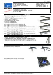
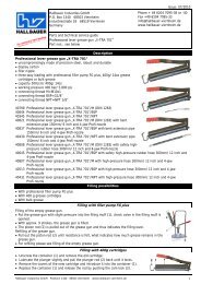
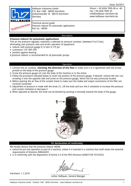
Pressure <strong>reducer</strong> <strong>for</strong> pneumatic applications<br />
This air line <strong>pressure</strong> regulator maintains a selected air <strong>pressure</strong> constant, (between 0 to12 bar),<br />
eliminating over <strong>pressure</strong> risks and erratic operation of equipment.<br />
�� <strong>reducer</strong> with <strong>pressure</strong> gauge 0-12 bar/ 0-175 psi<br />
�� connection 1/4" BSP (f/f)<br />
�� protects against wearing<br />
A <strong>pressure</strong> <strong>reducer</strong> is recommended <strong>for</strong> all pneumatic pumps<br />
Issue: 02/2011<br />
Phone + 49 6204 7095-38 or -40<br />
Fax +49 6204 7095-33<br />
info@hallbauer-viernheim.de<br />
www.hallbauer-viernheim.de<br />
Operation<br />
1. Connect the air conduits, checking the direction of the flow to make sure it is in agreement with the arrows<br />
printed on the body of the <strong>pressure</strong> gauge<br />
2. Screw the <strong>pressure</strong> gauge (2) onto the body of the machine or to the airline<br />
3. Follow the procedure indicated below to invert the position of the <strong>pressure</strong> gauge, if desired: remove the rear nut,<br />
screwing it onto the opposite side and screw on the <strong>pressure</strong> gauge, where the nut was previously located<br />
4. Be<strong>for</strong>e opening the air flow of the conduit check to make sure the intake and output connections of the filter are<br />
correctly connected<br />
5. Adjustment of <strong>pressure</strong> is made with the knob (1). Lift the knob and turn the it clockwise to increase the <strong>pressure</strong><br />
and counter clockwise to decrease it<br />
6. When adjusted as desired, the knob can be blocked by pushing it vertically towards the body of the gauge<br />
EC declaration of con<strong>for</strong>mity<br />
We hereby declare that the <strong>pressure</strong> <strong>reducer</strong> 40596<br />
�� cannot be put into operation as part of a machine, unless it is inserted in a machine that itself meets the essential<br />
requirements of Directive 2006/42/EC.<br />
�� is in con<strong>for</strong>mity with the dispositions of Article 3.3 of the PED Directive (DIRECTIVE 97/23/EC)<br />
<strong>Viernheim</strong>, 1.1.2010 ________________________________<br />
Lothar <strong>Hallbauer</strong>, General Manager<br />
<strong>Hallbauer</strong> Industries GmbH Postfach 1340 68503 <strong>Viernheim</strong> www.hallbauer-viernheim.de 1
<strong>Hallbauer</strong> Industries GmbH<br />
P.O. Box 1340 68503 <strong>Viernheim</strong><br />
Industriestraße 18 68519 <strong>Viernheim</strong><br />
Germany<br />
Technical service guide<br />
<strong>Maintenance</strong> <strong>unit</strong> <strong>for</strong> pneumatic applications<br />
Part no.: 80027<br />
Description<br />
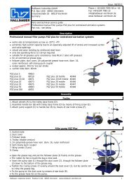
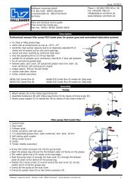
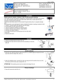
<strong>Maintenance</strong> <strong>unit</strong> <strong>for</strong> pneumatic applications<br />
�� water separator/<strong>pressure</strong> <strong>reducer</strong> with <strong>pressure</strong> gauge 0-12 bar/ 0-175 PSI<br />
�� oiler<br />
�� connection 1/4" BSP (f/f)<br />
�� protects against wearing<br />
�� consisting of water separator, <strong>pressure</strong> <strong>reducer</strong> and oiler<br />
<strong>Maintenance</strong> <strong>unit</strong>s are recommended <strong>for</strong> all pneumatic pumps<br />
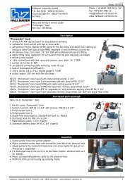
Operation<br />
Issue: 02/2011<br />
Phone + 49 6204 7095-38 or -40<br />
Fax +49 6204 7095-33<br />
info@hallbauer-viernheim.de<br />
www.hallbauer-viernheim.de<br />
�� Connect the air conduits, checking the direction of the flow to make sure it is in agreement with the arrows<br />
printed on the body of the <strong>pressure</strong> gauge<br />
�� Unscrew oiler (1), fill in hydraulic oil of low consistency, replace oiler<br />
�� Open adjusting screw (2) by means of screw driver and adjust oil quantity which is requested to be dispensed to<br />
compressed air<br />
�� Connect with compressed air<br />
�� Adjustment of <strong>pressure</strong> is made with the knob (3). Lift the knob and turn the it clockwise to increase the <strong>pressure</strong><br />
and counter clockwise to decrease it<br />
�� When adjusted as desired, the knob can be blocked by pushing it vertically towards the body of the gauge<br />
Please observe recommended <strong>pressure</strong> range of the connected <strong>unit</strong><br />
�� Water separator (5) with outlet valve (6)<br />
EC declaration of con<strong>for</strong>mity<br />
We hereby declare that the <strong>pressure</strong> <strong>reducer</strong> 40596<br />
�� cannot be put into operation as part of a machine, unless it is inserted in a machine that itself meets the essential<br />
requirements of Directive 2006/42/EC.<br />
�� is in con<strong>for</strong>mity with the dispositions of Article 3.3 of the PED Directive (DIRECTIVE 97/23/EC)<br />
<strong>Viernheim</strong>, 1.1.2010 ________________________________<br />
Lothar <strong>Hallbauer</strong>, General Manager<br />
<strong>Hallbauer</strong> Industries GmbH Postfach 1340 68503 <strong>Viernheim</strong> www.hallbauer-viernheim.de 2