Grease bucket pump BMP-16 - Hallbauer Viernheim
Grease bucket pump BMP-16 - Hallbauer Viernheim
Grease bucket pump BMP-16 - Hallbauer Viernheim

Create successful ePaper yourself
Turn your PDF publications into a flip-book with our unique Google optimized e-Paper software.
<strong>Hallbauer</strong> Industries GmbH<br />
P.O. Box 1340 68503 <strong>Viernheim</strong><br />
Industriestraße 18 68519 <strong>Viernheim</strong><br />
Germany<br />
Parts and technical service guide<br />
<strong>Grease</strong> <strong>bucket</strong> <strong>pump</strong> <strong>BMP</strong> <strong>16</strong><br />
Part no.: 150000<br />
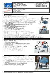
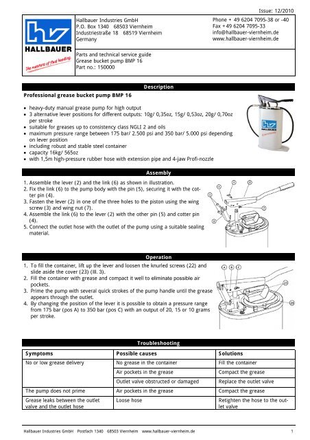
Professional grease <strong>bucket</strong> <strong>pump</strong> <strong>BMP</strong> <strong>16</strong><br />
Description<br />
�� heavy-duty manual grease <strong>pump</strong> for high output<br />
�� 3 alternative lever positions for different outputs: 10g/ 0,35oz, 15g/ 0,53oz, 20g/ 0,70oz<br />
per stroke<br />
�� suitable for greases up to consistency class NGLI 2 and oils<br />
�� maximum pressure range between 175 bar/ 2.500 psi and 350 bar/ 5.000 psi depending<br />
on lever position<br />
�� including robust and stable steel container<br />
�� capacity <strong>16</strong>kg/ 565oz<br />
�� with 1,5m high-pressure rubber hose with extension pipe and 4-jaw Profi-nozzle<br />
Assembly<br />
1. Assemble the lever (2) and the link (6) as shown in illustration.<br />
2. Fix the link (6) to the <strong>pump</strong> body with the pin (5), securing it with the cotter<br />
pin (4).<br />
3. Fasten the lever (2) in one of the three holes to the piston using the wing<br />
screw (3) and wing nut (7).<br />
4. Assemble the link (6) to the lever (2) with the other pin (5) and cotter pin<br />
(4).<br />
5. Connect the outlet hose with the outlet of the <strong>pump</strong> using a suitable sealing<br />
material.<br />
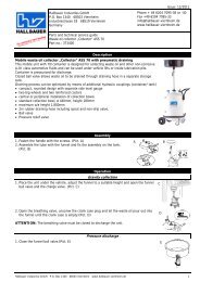
Operation<br />
1. To fill the container, lift up the lever and loosen the knurled screws (22) and<br />
slide aside the cover (23) (Ill. 3).<br />
2. Fill the container with grease and compact it well to eliminate possible air<br />
pockets.<br />
3. Prime the <strong>pump</strong> with several quick strokes of the <strong>pump</strong> handle until the grease<br />
appears through the outlet.<br />
4. By changing the position of the lever it is possible to obtain a pressure range<br />
from 175 bar (pos A) to 350 bar (pos C) with an output of 20, 15 or 10 grams<br />
per stroke.<br />
Troubleshooting<br />
Issue: 12/2010<br />
Phone + 49 6204 7095-38 or -40<br />
Fax +49 6204 7095-33<br />
info@hallbauer-viernheim.de<br />
www.hallbauer-viernheim.de<br />
Symptoms Possible causes Solutions<br />
No or low grease delivery<br />
No grease in the container Fill the container<br />
Air pockets in the grease Compact the grease<br />
Outlet valve obstructed or damaged Replace the outlet valve<br />
The <strong>pump</strong> does not prime Air pockets in the grease Compact the grease<br />
<strong>Grease</strong> leaks between the outlet Loose hose Retighten the hose to the out-<br />
valve and the outlet hose<br />
let valve<br />
<strong>Hallbauer</strong> Industries GmbH Postfach 1340 68503 <strong>Viernheim</strong> www.hallbauer-viernheim.de 1
<strong>Grease</strong> <strong>bucket</strong> <strong>pump</strong> <strong>BMP</strong> <strong>16</strong> Part no.: 150000<br />
Issue: 12/2010<br />
Disassembling procedure<br />
�� Dismount the lever (2) and the link (6) following the installation procedure, reversing each step.<br />
�� Remove the cover (23) and unscrew the screws (11) to be able to remove the <strong>pump</strong> set.<br />
�� Unscrew the nut (21) and thrust washer (20) from the piston (9).<br />
�� Unscrew the <strong>pump</strong> tube (18) from the <strong>pump</strong> body (13) and remove the seal (14), the inner tube (8), the guide<br />
washer (15), the valve top (<strong>16</strong>) and the valve base (17).<br />
�� Take out the piston (9) from the <strong>pump</strong> body (13) and remove the quad-ring (10).<br />
�� Reassemble following the same instructions, reversing each step.<br />
Parts list<br />
Repair kit<br />
Pos. Part.No. Description<br />
4, 10, 14, 15, <strong>16</strong>, 17<br />
Parts available separately<br />
715431 Seals<br />
12 715412 Outlet valve<br />
24 715424 Cover<br />
25 815600 Cover seal<br />
715429 Outlet hose<br />
<strong>Hallbauer</strong> Industries GmbH Postfach 1340 68503 <strong>Viernheim</strong> www.hallbauer-viernheim.de 2