Seko OPL Basic System Instru.. - UK
Seko OPL Basic System Instru.. - UK
Seko OPL Basic System Instru.. - UK

Create successful ePaper yourself
Turn your PDF publications into a flip-book with our unique Google optimized e-Paper software.
<strong>OPL</strong> <strong>Basic</strong> – Laundry system<br />
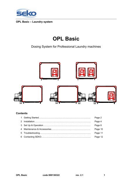
<strong>OPL</strong> <strong>Basic</strong><br />
Dosing <strong>System</strong> for Professional Laundry machines<br />
Contents<br />
1 Getting Started……………………………………………………………. Page 2<br />
2 Installation…………………………………………………………………. Page 4<br />
3 Set Up & Operation………………………………………………………. Page 8<br />
4 Maintenance & Accessories…..………………………………………… Page 10<br />
5 Troubleshooting…………………………………………………………… Page 11<br />
6 Contacting SEKO.………………………………………………………… Page 12<br />
<strong>OPL</strong> <strong>Basic</strong> code 000136322 rev. 2.1 1
GETTING STARTED<br />
INSTALLATION<br />
SET UP & OPERATION<br />
MAINTENANCE &<br />
ACCESSORIES<br />
TROUBLESHOOTING<br />
CONTACTING SEKO<br />
<strong>OPL</strong> <strong>Basic</strong> – Laundry system<br />
1 GETTING STARTED<br />
1.1 WELCOME<br />
Get ready for a whole new experience. <strong>OPL</strong> <strong>Basic</strong> has a fresh, new look and it’s easier than<br />
ever to use.<br />
This proven chemical dispensing system is engineered to dispense one or two chemicals.<br />
Chemical feeds either by a trigger signal directly from the washer or manually by the operator<br />
with the activating switches on the front cover. It is also possible to activate the unit dispensing<br />
with a remote switch (optional) to be connected to the <strong>OPL</strong> <strong>Basic</strong>.<br />
A unique “Product Lockout” feature helps you control costs and product consumption.<br />
This book explains how to install and set up the <strong>OPL</strong> <strong>Basic</strong> and where to turn for help so you<br />
can enjoy the most intuitive dosing system yet.<br />
<br />
Please review this manual carefully. Pay particular attention to warnings and<br />
precautions. Always follow good safety procedures, including the use of proper<br />
clothing, eye and face protection.<br />
Please read through entire manual and choose operating mode before you begin<br />
installation.<br />
1.2 WHAT’S IN THE BOX?<br />
Before you start, check that your box contains the following items:<br />
• <strong>OPL</strong> <strong>Basic</strong> system;<br />
• <strong>Instru</strong>ction manual;<br />
• Mounting kit;<br />
• PVC tube: 7/16” OD x 5/16” ID (6 ft) each pump.<br />
1.3 TECHNICAL FEATURES<br />
• Power supply: 115/208/230 Vac 50/60 Hz<br />
• Consumption: 14 W<br />
• Fuse: 315mA @ 250VAC, 5x20 type<br />
• Protection of the <strong>System</strong>: The gasketed enclosure on the <strong>OPL</strong> <strong>Basic</strong> is highly water<br />
resistant and the electronics are further protected within the enclosure.<br />
<strong>OPL</strong> <strong>Basic</strong> code 000136322 rev. 2.1 2
<strong>OPL</strong> <strong>Basic</strong> – Laundry system<br />
GETTING STARTED<br />
INSTALLATION<br />
SET UP & OPERATION<br />
1.4 WARNINGS<br />
<br />
<br />
Check the voltage of the main power source and make sure that it matches one of<br />
the three available input voltages (115/208/230 vac) of the transformer inside the<br />
<strong>OPL</strong> BASIC.<br />
All electrical connections to the <strong>OPL</strong> BASIC should first be verified with a meter.<br />
Application of incorrect voltage will permanently damage the unit and is not<br />
covered under warranty. Avoid wiring to any power source that has large<br />
fluctuations in voltage and/or is prone to surges. Refer to the wiring diagram in this<br />
manual for all power and signal connections.<br />
MAINTENANCE &<br />
ACCESSORIES<br />
TROUBLESHOOTING<br />
CONTACTING SEKO<br />
<br />
<br />
<br />
<br />
<br />
For all connections, please refer to the circuit board schematic contained in this<br />
manual<br />
Check the model of the equipment you have purchased for the references about<br />
installation, setting and programming.<br />
CAUTION: The <strong>OPL</strong> BASIC has high voltage connected to the transformer. Always<br />
disconnect power when servicing the unit.<br />
CAUTION: During installation and electrical connections remove all power from the<br />
dishwasher.<br />
Failure to follow these instructions may lead to personal injury, damage to the<br />
product or poor product performance.<br />
1.5 MATERIALS REQUIRED DURING INSTALLATION<br />
• Two pole wire: 2x0.75 - H-05 VVF (qty 2; length 6 ft - for trigger signal);<br />
• Two pole wire: 2x1.5 - H-05 VVF (qty 1; length 6 ft - for power supply);<br />
• ¼” OD copper tubing (qty 1; length 6 ft - for water solenoid valve).<br />
<br />
<br />
The lengths indicated above are for typical installations. Your installation may<br />
require different lengths.<br />
An installation kit is available (see Maintenance & Accessories).<br />
<strong>OPL</strong> <strong>Basic</strong> code 000136322 rev. 2.1 3
<strong>OPL</strong> <strong>Basic</strong> – Laundry system<br />
GETTING STARTED<br />
INSTALLATION<br />
SET UP & OPERATION<br />
2 INSTALLATION<br />
Mount the unit on a nearby wall (using suitable hardware) of the laundry machine.<br />
Locate a mounting spot where operators can access the Start button and within 20 feet of the<br />
chemical supply. Always install the system at a safe, convenient height for the operators to load<br />
or unload solid containers or to perform maintenance.<br />
Check all applicable plumbing and electrical codes before proceeding with the installation. This<br />
will help to ensure that the system is installed in safe and suitable manner. A wiring schemaatic<br />
of the laundry machine should be used as reference for making electrical connections this is<br />
typically provided by the laundry machine manufacturer if one cannot be located on the machine<br />
itself.<br />
MAINTENANCE &<br />
ACCESSORIES<br />
TROUBLESHOOTING<br />
CONTACTING SEKO<br />
2.1 MOUNTING THE SYSTEM<br />
Apply the panel unit system with the brackets and screws supplied:<br />
• Determine a suitable location for the system;<br />
• Using the bracket as a template, mark and drill holes for bolting the system to the wall;<br />
• Insert the anchors in the holes;<br />
• Bolt the bracket in place with the hardware provided;<br />
• Mount the system with the bracket as the picture below;<br />
• Open the Cabinet Front by unscrewing the upper screws ¼ of a turn:<br />
Picture 1<br />
<strong>OPL</strong> <strong>Basic</strong> code 000136322 rev. 2.1 4
<strong>OPL</strong> <strong>Basic</strong> – Laundry system<br />
2.2 CIRCUIT BOARD DIAGRAM<br />
CAUTION!!! Turn off the circuit breaker before installing or servicing the <strong>OPL</strong> <strong>Basic</strong>.<br />
GETTING STARTED<br />
A B C D E<br />
INSTALLATION<br />
F<br />
SET UP & OPERATION<br />
G<br />
MAINTENANCE &<br />
ACCESSORIES<br />
TROUBLESHOOTING<br />
H<br />
I<br />
J<br />
K<br />
CONTACTING SEKO<br />
Picture 2<br />
A) Potentiometer for setting the volume of the buzzer (VOLUME).<br />
B) Potentiometer for setting the delay time (DELAY) for pump/solenoid 1.<br />
Adjustable from 0 seconds to 5 minutes<br />
C) Potentiometer for setting the run time (DOSING) for pump/solenoid 1.<br />
Adjustable from 1 second to 5 minutes<br />
D) Potentiometer for setting the delay time (DELAY) for pump/solenoid 2.<br />
Adjustable from 0 seconds to 5 minutes<br />
E) Potentiometer for setting the run time (DOSING) for pump/solenoid 2.<br />
Adjustable from 1 second to 5 minutes<br />
F) Dip-switch for pause time (LOCK-OUT). Lockout times can be set in 5 minute<br />
increments up to 75 minutes by setting the dipswitches as follows:<br />
DIPSWITCH 1 5min<br />
DIPSWITCH 2 10min<br />
DIPSWITCH 3 20min<br />
DIPSWITCH 4 40min<br />
G) Jumper for CALIBRATION<br />
H) Input connector for level float switch:<br />
LEV1 for pump 1<br />
LEV2 for pump 2<br />
I) Input connector for remote control:<br />
TRIG.1 for pump/solenoid 1<br />
TRIG.2 for pump/solenoid 2<br />
The voltage to be applied may vary from 20 to 230<br />
J) Jumper for selecting the power supply voltage of the device. The voltages that can be applied are<br />
115 – 208 – 230 VAC.<br />
K) Power-supply connector for device PWR<br />
<strong>OPL</strong> <strong>Basic</strong> code 000136322 rev. 2.1 5
<strong>OPL</strong> <strong>Basic</strong> – Laundry system<br />
2.3 ELECTRICAL CONNECTIONS<br />
<br />
CAUTION: The <strong>OPL</strong> BASIC has high voltage connected to the transformer. Always<br />
disconnect power when servicing the unit.<br />
GETTING STARTED<br />
INSTALLATION<br />
SET UP & OPERATION<br />
<br />
All electrical connections to the <strong>OPL</strong> BASIC system should first be verified with a<br />
meter. Application of incorrect voltage will permanently damage the unit and is not<br />
covered under warranty. Avoid wiring to any power source that has large<br />
fluctuations in voltage and/or is prone to surges. Refer to the wiring diagram in this<br />
manual for all power and signal connections. All wiring must conform to local<br />
electrical codes.<br />
MAINTENANCE &<br />
ACCESSORIES<br />
TROUBLESHOOTING<br />
CONTACTING SEKO<br />
2.3.1 Main Power Connection (Picture 2)<br />
To wire main power connection:<br />
• Check the voltage of the main power source and make sure that it matches one of the three<br />
available input voltages (115/208/230 Vac) of the transformer;<br />
• Move the jumper to the proper terminals to set the input voltage (Picture 2) before connecting<br />
the power supply:<br />
• Disconnect all power from the laundry machine<br />
• Connect leads from the main power source to the Power terminals on the circuit board (Picture<br />
2).<br />
2.3.2 Other connections<br />
• Connect leads from the terminals on the level float switch (optional) to the terminal (LEV-1/2)<br />
on the circuit board (Picture 2).<br />
• If using the console (optional), connect leads from the console to the appropriate connector<br />
positioned on the display circuit board.<br />
For units using an external trigger signal, wire signal from signal source to the 20-230Vac signal<br />
input terminal (refer to wiring schematic).<br />
<br />
The <strong>OPL</strong> BASIC is factory set for 230 Vac Power Supply.<br />
<strong>OPL</strong> <strong>Basic</strong> code 000136322 rev. 2.1 6
<strong>OPL</strong> <strong>Basic</strong> – Laundry system<br />
2.5 Plumbing<br />
GETTING STARTED<br />
INSTALLATION<br />
SET UP & OPERATION<br />
MAINTENANCE &<br />
ACCESSORIES<br />
TROUBLESHOOTING<br />
CONTACTING SEKO<br />
Liquid product plumbing:<br />
Solid product plumbing:<br />
Connect 7/16” OD x 5/16” ID tubing from the output (right) side<br />
of the pump to the injection point.<br />
Connect 7/16” OD x 5/16” ID tubing from the chemical source to<br />
the suction (left) side of the pump.<br />
A powder or solid type feeder (not provided) should be used for<br />
dispensing dry detergent products. Follow the instructions<br />
included with the detergent feeder for installation, and<br />
recommended water temperature/pressure. Make sure that the<br />
detergent feeder (bowl) is located in a position on the wall that<br />
allows the feeding of the detergent in the laundry machine<br />
through gravity.<br />
• Cut a suitable length of ¼” OD copper tubing (not<br />
provided) and connect between the input side of the<br />
water solenoid valve and the water source;<br />
• Cut a suitable length of ¼” OD copper tubing (not<br />
provided) and connect between the output of water<br />
solenoid to a powder or solid detergent feeder;<br />
• Cut a suitable length of tubing (not provided) and<br />
connect between the output of detergent feeder to<br />
the elbow connector;<br />
• Carefully tighten the compression nuts on the water<br />
solenoid; over tightening may cause solenoid to leak.<br />
Tighten connections to the water source and detergent<br />
feeder as needed.<br />
Picture 3<br />
The water solenoid valve does not have a set direction for input/output<br />
Always use the foot filter and make sure that it reaches the bottom of the<br />
product container. Periodically check and clean the filter of buildup or debris.<br />
<strong>OPL</strong> <strong>Basic</strong> code 000136322 rev. 2.1 7
GETTING STARTED<br />
INSTALLATION<br />
SET UP & OPERATION<br />
MAINTENANCE &<br />
ACCESSORIES<br />
<strong>OPL</strong> <strong>Basic</strong> – Laundry system<br />
3 SET UP & OPERATION<br />
3.1 PROGRAMMING<br />
3.1.1 Pump/Solenoid run time:<br />
By calibration (max run time is 5 minutes)<br />
1. Be sure the DOSING trimmer is set completly counterclockwise<br />
2. Locate the terminal labeled “TYPE” on the far left side of the circuit board —<br />
close this terminal with the jumper to enter in CALIBRATION MODE. (led are<br />
blinking red).<br />
3. While holding a measuring cup or flask under the outlet of the pump, press the<br />
“Start Dosing” switch and release when the pump starts (led is steady red). Let<br />
the pump or solenoid run until desired amount of chemical is dispensed then<br />
press the “Start Dosing” switch again to stop. (led is blinking red) and buzzer will<br />
sound (1 beep). The <strong>OPL</strong> <strong>Basic</strong> run time is now programmed. Repeat these<br />
steps if new volume is required.<br />
4. Remove the jumper from the terminal “TYPE” and leave circuit open for<br />
“Operation” mode. (To prevent loss of the jumper replace it over one terminal<br />
pin).<br />
TROUBLESHOOTING<br />
CONTACTING SEKO<br />
1 s.<br />
Default dosing time is 1 second.<br />
5 minutes<br />
3.1.2 Delay time: (max delay time is 5 minutes)<br />
1. You set the delay, using the trimmer DELAY on the circuit board<br />
.<br />
1 s.<br />
5 minutes<br />
3.1.3 Lock-out time: (max lock-out time is 75 minutes)<br />
This feature defeats consecutive dispensing of product for a pre-determined interval. Select a<br />
combination of switches 1-4 to program total lock-out time.<br />
Example: For 15 minute lock-out, set switches #1 and #2 to ON with all other<br />
switches OFF.<br />
For maximum lock-out (75 min) set all switches ON.<br />
For no lock-out, set all switches OFF.<br />
<strong>OPL</strong> <strong>Basic</strong> code 000136322 rev. 2.1 8
<strong>OPL</strong> <strong>Basic</strong> – Laundry system<br />
GETTING STARTED<br />
INSTALLATION<br />
SET UP & OPERATION<br />
MAINTENANCE &<br />
ACCESSORIES<br />
TROUBLESHOOTING<br />
CONTACTING SEKO<br />
3.2 OPERATION<br />
3.2.1 Manual activation<br />
Press the “Start Dosing” button on the cover or on the remote switch. The <strong>OPL</strong> <strong>Basic</strong> will begin<br />
counting down the delay time (if used) (the led is blinking green) and will then run the<br />
pump/solenoid for the amount of time programmed (the led is steady green). Once the lock-out<br />
time expires the pump/solenoid will be ready to restart.<br />
3.2.2 Signal activation<br />
When the signal input on the circuit board receives a 20-240 VAC trigger signal for at least 3 full<br />
seconds, the delay time (if used - the led is blinking green) will begin counting down. Then the<br />
pump/solenoid will run for the amount of time programmed (the led is steady green). Once the<br />
lock-out time expires the pump or solenoid will be ready to restart. (NOTE: If after calibrating<br />
and connecting the trigger signals you want to disable the manual feed option, remove<br />
the jumpers inside the front cover for the “Start Dosing” switches).<br />
3.2.3 Lock-out signal feature<br />
The lock-out time is independent for the system with two dispensers.<br />
During the lock-out time the led is blinking green.<br />
3.2.4 Disabling the start button<br />
There is a jumper marked “Pump1” or “Pump2” on the display circuit board that can be used to<br />
prevent manual activation in certain applications, or to allow manual activation by remote pushbutton<br />
only. This jumper only affects the integrated start button. A remote start button, or trigger<br />
signal, can always be used to activate the pump.<br />
• When the jumper is ON (close), the on-board start button is functional.<br />
• When the jumper OFF(open), the on-board start button is disabled.<br />
3.2.5 Alarms<br />
The two-color LED will be red and the buzzer sounds when there is a level alarm status. It is<br />
necessary to connect a level probe. (Optional - Picture 2).<br />
3.2.6 LED color descriptions:<br />
Green: pump running.<br />
Blinking green fast: the pump is in delay time.<br />
Blinking green slow: the pump is in lock-out time.<br />
Red: the pump is running in calibration mode. (See section 3.1.1 for full description)<br />
Blinking red: the system is in calibration mode. (See section 3.1.1 for full description)<br />
<strong>OPL</strong> <strong>Basic</strong> code 000136322 rev. 2.1 9
<strong>OPL</strong> <strong>Basic</strong> – Laundry system<br />
4 MAINTENANCE & ACCESSORIES<br />
GETTING STARTED<br />
INSTALLATION<br />
SET UP & OPERATION<br />
MAINTENANCE &<br />
ACCESSORIES<br />
TROUBLESHOOTING<br />
CONTACTING SEKO<br />
4.1 MAINTENANCE<br />
Routine maintenance on the <strong>OPL</strong> BASIC unit includes preventive maintenance on the squeeze<br />
tubes and keeping the unit clean. Repairs to the unit involve modular component replacements.<br />
This minimizes spare parts inventory requirements and speeds up the service process in the<br />
field.<br />
4.1.1 Squeeze Tube Replacement<br />
Replace squeeze tubes on regular maintenance intervals. A planned preventive maintenance<br />
schedule will insure replacement before the tube fails. In the event the tube does rupture, clean<br />
all product from pump with a damp cloth.<br />
• Disconnect power before servicing the unit;<br />
• Remove the transparent lid from the pump;<br />
• Before removing the old tube, position roller assembly with rollers in a vertical position;<br />
• Remove the old tube starting from the left; lift the tube and rotate the roller assembly clockwise;<br />
• Before inserting the new tube, position roller assembly with rollers in horizontal position;<br />
• Insert new tube with flat sides facing towards the front; from the left side rotate the roller holder<br />
clockwise as you press the pump tube in place;<br />
• Insert the transparent lid.<br />
4.2 ACCESSORIES<br />
It is possible to connect the system to a level float switch.<br />
Material for the installation:<br />
• Two pole wire: 2x1.5 - H-05 VVF (qty 1; length 6 ft - for power supply);<br />
• Two pole wire: 2x0.75 - H-05 VVF (qty 2; length 6 ft - for trigger signal);<br />
• ¼” OD copper tubing (qty 1; length 6 ft - for water solenoid valve);<br />
<strong>OPL</strong> <strong>Basic</strong> code 000136322 rev. 2.1 10
GETTING STARTED<br />
INSTALLATION<br />
SET UP & OPERATION<br />
MAINTENANCE &<br />
ACCESSORIES<br />
TROUBLESHOOTING<br />
CONTACTING SEKO<br />
<strong>OPL</strong> <strong>Basic</strong> – Laundry system<br />
5 TROUBLESHOOTING<br />
5.1 POWER LIGHT DOES NOT ILLUMINATE:<br />
• Check fuses on the circuit boards.<br />
• Check input terminals on board for correct input voltage. Refer to the circuit board<br />
diagram.<br />
5.2 PUMP(S) OR SOLENOID WILL NOT ACTIVATE:<br />
• Check pump output terminals for loose screws and disconnected wires.<br />
• Check for proper voltage across motor windings (or solenoid contacts).<br />
• Check for obstruction in pump head (or solenoid).<br />
5.3 TOO MUCH DETERGENT:<br />
• Check the voltage to the system.<br />
• Check the concentration set point for the proper setting.<br />
• Check the probe in the wash tank for corrosion or foreign particles.<br />
• Check for open wires between the probe and the connections to the circuit board barrier.<br />
5.4 TOO LITTLE DETERGENT:<br />
• Check the voltage to the system.<br />
• Check pump operation for proper speed (or check bowl feeder for obstructions).<br />
5.5 PUMP RUNS TOO SLOWLY:<br />
• Check roller block for binding.<br />
• Check for proper input voltage (24 VDC applied to the pump motor terminals will result in<br />
the highest speeds).<br />
• Check for lubrication on squeeze tube.<br />
<strong>OPL</strong> <strong>Basic</strong> code 000136322 rev. 2.1 11
<strong>OPL</strong> <strong>Basic</strong> – Laundry system<br />
6 CONTACTING SEKO<br />
Website: www.seko.com<br />
GETTING STARTED<br />
INSTALLATION<br />
SET UP & OPERATION<br />
MAINTENANCE &<br />
ACCESSORIES<br />
TROUBLESHOOTING<br />
CONTACTING SEKO<br />
SEKO Italia<br />
SEKO Asia pacific<br />
SEKO do Brasil<br />
SEKO Deutschland<br />
SEKO France<br />
SEKO Iberica<br />
SEKO Southern Africa<br />
SEKO <strong>UK</strong><br />
SEKO USA<br />
<strong>OPL</strong> <strong>Basic</strong> code 000136322 rev. 2.1 12