AII-3000 A Series Portable Oxygen Analyzer - Advanced Instruments ...
AII-3000 A Series Portable Oxygen Analyzer - Advanced Instruments ...
AII-3000 A Series Portable Oxygen Analyzer - Advanced Instruments ...

Create successful ePaper yourself
Turn your PDF publications into a flip-book with our unique Google optimized e-Paper software.
ISO 9001:2008, Certificate #485<br />
<strong>AII</strong>-<strong>3000</strong> AHC<br />
<strong>AII</strong>-<strong>3000</strong> A<br />
Copyright © 10/10 All Rights Reserved<br />
Analytical Industries Inc.,<br />
2855 Metropolitan, Pomona, CA 91767 USA.<br />
Tel: 909-392-6900, Fax: 909-392-3665<br />
e-mail: sales-medical@aii1.com, web: www.aii1.com<br />
This manual may not be reproduced in whole or in part without<br />
the prior written consent of Analytical Industries Inc.<br />
<strong>AII</strong>-<strong>3000</strong> MHC<br />
<strong>AII</strong>-<strong>3000</strong> M
Table of Contents<br />
1 Introduction 1<br />
1.1 Indications for Use<br />
1.2 Intended Use<br />
1.3 Device Description<br />
2 Quality Control Certification 3<br />
3 Safety Warnings 4<br />
4 Start-up<br />
4.1 Contents of Shipping Container<br />
4.2 Install Batteries<br />
4.3 Install <strong>Oxygen</strong> Sensor<br />
4.4 Controls<br />
4.5 Start-up Test<br />
4.6 Alarms (<strong>AII</strong>-<strong>3000</strong> M <strong>Oxygen</strong> Monitor)<br />
4.7 Calibration<br />
4.8 Mounting<br />
5 Operation<br />
5.1 Principle of Operation<br />
5.2 Application Considerations<br />
5.3 Calibration<br />
5.4 Sampling<br />
6 Maintenance<br />
6.1 Serviceability<br />
6.2 Battery Replacement<br />
6.3 <strong>Oxygen</strong> Sensor Replacement<br />
7 Troubleshooting<br />
8 Specifications<br />
8.1 Spare Parts & Accessories<br />
9 Warranty<br />
10 Material Safety Data Sheet (MSDS)<br />
10.1 Disposal<br />
1<br />
2<br />
2<br />
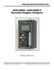
1 Introduction<br />
Congratulations on your purchase, these Instructions for Use describe the precautions,<br />
set-up, operation, maintenance and specifications of the <strong>AII</strong>-<strong>3000</strong><br />
<strong>Series</strong> <strong>Oxygen</strong> <strong>Analyzer</strong>s.<br />
This symbol means CAUTION – Failure to read and comply with the<br />
Instructions for Use could damage the device and possibly jeopardize<br />
the well being of the user.<br />
Note: <strong>Advanced</strong> <strong>Instruments</strong> Inc. cannot warrant any damage resulting from<br />
the misuse, unauthorized repair or improper maintenance of the device.<br />
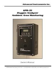
1.1 Indications for Use<br />
The <strong>AII</strong>-<strong>3000</strong> <strong>Series</strong> <strong>Oxygen</strong> <strong>Analyzer</strong>s are intended to measure and display the<br />
concentration of oxygen in compressed breathing air tanks intended for scuba<br />
diving, for personnel safety, area monitoring, O2 deficiency in confined spaces,<br />
checking breathing air tanks and confirming the O2 levels prior to welding.<br />
Users must read the following statements as they are essential to reducing<br />
the risk of use error due to ergonomic features of the device or<br />
the environment in which the device is intended to be used.<br />
The devices have been designed and manufactured in such a way that when<br />
used under the conditions and for the purposes intended, they will not compromise<br />
the clinical condition or the safety of patients, or safety of the users or<br />
other persons.<br />
Conformity with essential requirements has been demonstrated by verifying the<br />
performance of the device under normal conditions, bench testing and determining<br />
that undesirable malfunctions constitute minimal risk to users.<br />
Do not sterilize, autoclave, liquid sterilize, immerse in any liquid or expose the<br />
device or accessories to steam, ethylene oxide or radiation sterilization.<br />
The device is intended to be re-usable. Should the device or accessories come<br />
in contact with patient bodily fluids, either dispose of the device or clean with a<br />
soft cloth dampened with 70% isopropyl alcohol solution in water and allow the<br />
components to air-dry before re-use .<br />
Do not operate the analyzer near equipment capable of emitting high levels of<br />
electromagnetic radiation as the reading may become unstable.<br />
i<br />
1
In order to obtain optimum performance, the operation of the device must be<br />
performed in accordance with these Instructions for Use. Maintenance should<br />
be performed only by trained personnel authorized by the manufacturer.<br />
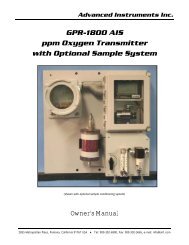
1.2 Intended Use<br />
The <strong>AII</strong>-<strong>3000</strong> <strong>Series</strong> <strong>Oxygen</strong> <strong>Analyzer</strong>s are intended to measure and display<br />
the concentration of oxygen in compressed breathing air tanks intended for<br />
scuba diving, for personnel safety, area monitoring, O2 deficiency in confined<br />
spaces, checking breathing air tanks and confirming the O2 levels prior to<br />
welding.<br />
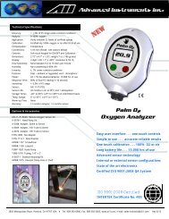
1.3 Device Description<br />
The <strong>AII</strong>-<strong>3000</strong> <strong>Series</strong> <strong>Oxygen</strong> <strong>Analyzer</strong>s can be positioned on a table top or<br />
pole (tripod wire stand and V-mount dovetail attachments are mounted on the<br />
back of the device) and are readily portable from one location to another.<br />
They provide continuous, fast, reliable and accurate oxygen measurements of<br />
up to respiratory care systems.<br />
The devices utilize an electrochemical galvanic fuel cell type oxygen sensor of<br />
the type that is extensively used to measure oxygen concentrations from 0%<br />
to 100% in gas streams. <strong>Oxygen</strong>, the fuel for this electrochemical transducer,<br />
diffusing into the sensor through a gas permeable membrane reacts chemically<br />
at the sensing electrode to produce an electrical current output proportional<br />
to the oxygen concentration in the gas phase. The sensor has an absolute<br />
zero meaning that when no oxygen is present to be chemically reacted<br />
the LCD displays 00.0 oxygen.<br />
The sensor’s signal output is linear over the entire range, remains virtually<br />
constant over the specified useful life and drops off sharply at the end. The<br />
sensor itself requires no maintenance and is simply replaced at the end of its<br />
useful life like a battery. Inasmuch as the sensor is a transducer in its own<br />
right, its expected life is not affected by whether the analyzer is ON or OFF.<br />
A battery powered state-of-the-art micro-processor converts the sensor’s signal<br />
output representing the partial pressure of oxygen in the gas stream being<br />
analyzed. The resulting oxygen reading is displayed by a large easy to read<br />
backlit liquid crystal display (LCD) that has a resolution of 0.1% oxygen. The<br />
microprocessor is controlled from a keypad and provides features like system<br />
diagnostics, warning indicators, controls and an alarm capability for continuous<br />
monitoring that enhance both safety and effectiveness.<br />
Prior to shipment, every device is thoroughly tested at the factory and documented<br />
in the form of a Quality Control Certification that is included in the<br />
Instructions for Use supplied with every device.<br />
2<br />
2 Quality Control Certification<br />
Customer:<br />
Model:<br />
Sensor:<br />
Electronics:<br />
Accessories:<br />
QC Test:<br />
________________________ Order No. _____________ Date: _______<br />
( ) <strong>AII</strong>-<strong>3000</strong> A <strong>Oxygen</strong> <strong>Analyzer</strong><br />
( ) <strong>AII</strong>-<strong>3000</strong> M <strong>Oxygen</strong> <strong>Analyzer</strong><br />
( ) <strong>AII</strong>-<strong>3000</strong> AHC <strong>Oxygen</strong> <strong>Analyzer</strong><br />
( ) <strong>AII</strong>-<strong>3000</strong> MHC <strong>Oxygen</strong> <strong>Analyzer</strong> S/N _______________<br />
( ) <strong>AII</strong>-11-60 or ( ) <strong>AII</strong>-11-60-HC S/N _______________<br />
A-1162 PCB Assembly Main Software Version _______________<br />
<strong>AII</strong>-<strong>3000</strong> A / M: CABL-1006 Cable, Coiled Phone Jack<br />
<strong>AII</strong>-<strong>3000</strong> AHC / MHC: A-3675 Adapter, 5/32” Tube to Sensor<br />
TUBE-1019 7/32” OD Tubing 3 ft.<br />
All units: BATT-1008 Battery, 1.5V AA (Qty 2)<br />
P-0187 Manual, Instructions for Use ……… Included ______<br />
PASS<br />
LCD display 3-1/2 digits ……………………………………………………. ______<br />
Battery symbol displays when battery is low ……………………….. ______<br />
Span adjustment +10-30% FS with 100% oxygen calibration ______<br />
Following calibration with 99-100% oxygen and flushing with<br />
ambient air, oxygen reading as displayed by LCD 20.9% +2% ____<br />
Span adjustment +10-30% FS with air calibration ……………….. ______<br />
Following calibration with air (20.9% oxygen) and exposing<br />
to 99-100% oxygen, LCD displays 100% +2% ……………………. ______<br />
Overall inspection for physical defects ………………………………... ______<br />
Qty<br />
Options: _____________________________________________ ____<br />
See Sec 8.1 ____________________________________________________ _____<br />
____________________________________________________<br />
____________________________________________________<br />
____________________________________________________<br />
Delivery: ____________________________________________________<br />
3<br />
_____<br />
____<br />
_____
3 Safety Warnings<br />
ALWAYS follow the statements below as they are essential to reducing<br />
the risk of use error due to ergonomic features of the device or the<br />
environment in which the device is intended to be used.<br />
‣ Only trained personnel who have read, understand and agree to follow<br />
the Instructions for Use should operate the device.<br />
‣ Retain the Instructions for Use for future reference.<br />
‣ Refer service needs to trained authorized personnel. Failure to do so may<br />
cause the device to fail and void the warranty.<br />
‣ Inspect the device and accessories before operating and ensure: (a)<br />
there is no evidence of physical damage; (b) the sensor (particularly the<br />
sensing surface) and electrical connections are dry; and, (c) the sensor is<br />
installed and upstream from any humidifying device for accurate calibration<br />
and oxygen readings.<br />
‣ Calibrate: (a) with a known source of air or dry 100% oxygen before<br />
using each day or after 8 hours of continuous use; (b) when the temperature<br />
or pressure of the operating environment changes; (c) if the<br />
oxygen sensor has been disconnected and reconnected; (d) after the<br />
battery or oxygen sensor has been replace.<br />
‣ Sampling flowing gas: (a) install the optional flow diverter and teeadapter<br />
in a vertical position as shown in Section 4.3 and (b) assure<br />
there is a tight fit between the flow diverter and tee adapter.<br />
‣ Sampling static, ambient or controlled atmospheres remove the flow<br />
diverter.<br />
‣ Clean the device and accessories in accordance with Section 6.1.2.<br />
‣ Battery replacement Section 6.2: (a) replace the batteries within twentyfour<br />
(24) hours of the battery symbol appearing on LCD display and (b)<br />
calibrate the analyzer after replacing the batteries.<br />
‣ <strong>Oxygen</strong> sensor installation or replacement Section 6.3: allow the new<br />
sensor to stabilize for 15-20 minutes in ambient air before attempting to<br />
calibrate.<br />
‣ Store the device by turning the power OFF and removing the batteries if<br />
the device will not be operated for over thirty (30) days.<br />
‣ Attempt to repeat the procedure that caused a perceived malfunction<br />
and refer to troubleshooting hints in Section 7 before concluding the<br />
device is faulty. If in doubt, contact the manufacturer for assistance.<br />
NEVER operate the device in any manner described below doing so<br />
may compromise the clinical condition or the safety of patients, users<br />
or other persons.<br />
‣ If the reading is unstable or a malfunction is suspected.<br />
‣ After the battery symbol appears in the LCD display.<br />
‣ Near equipment capable of emitting high levels of electromagnetic radiation<br />
(EMI) or radio frequency interference (RFI).<br />
‣ Expose the device; particularly the LCD display or sensor to sources of<br />
extreme heat, cold or excessive sunlight beyond the device’s storage temperature<br />
range, refer to Section 8 for extended periods of time.<br />
‣ In a gas stream with a vacuum greater than 14” water column.<br />
‣ Immerse the device, oxygen sensor or coiled cable in any liquid.<br />
‣ Outside of the parameters specified in Section 8 particularly at flow rates<br />
greater than 10 liters per minute - the backpressure generated produces<br />
erroneously high oxygen readings.<br />
‣ Calibrate: (a) with 20.9% oxygen or room air with the intent of taking<br />
oxygen measurements at oxygen levels above 30% oxygen; (b) in a humidified<br />
gas stream or atmosphere; (c) without allowing a newly installed<br />
sensor to stabilize for 15-20 minutes in ambient air.<br />
‣ Attempt to sterilize, autoclave, liquid sterilize, immerse in any liquid or<br />
expose the device or accessories to steam, ethylene oxide or radiation<br />
sterilization.<br />
‣ In the presence of flammable gases.<br />
‣ Open the main compartment of the device, except to change the integral<br />
oxygen sensor of the <strong>AII</strong>-<strong>3000</strong> AHC or <strong>AII</strong>-<strong>3000</strong> MHC <strong>Oxygen</strong> <strong>Analyzer</strong>s.<br />
‣ Open the oxygen sensor or probe the sensing surface, refer to Section 10<br />
in the event the sensor should leak and someone comes in contact with<br />
the electrolyte from inside the sensor.<br />
‣ Operate with a cable that appears worn, torn or cracked, or, allow an<br />
excess length of cable near the patient’s head or neck; secure it to the bed<br />
rail or other suitable object to avoid the possibility of strangulation.<br />
‣ Allow the device or oxygen sensor to be serviced, repaired or altered by<br />
anyone except trained personnel – failure to do so may endanger the<br />
patient or damage the device rendering the warranty null and void.<br />
4<br />
5
4 Start-Up<br />
4.1 Contents of Shipping Container:<br />
4.1.1 <strong>AII</strong>-<strong>3000</strong> A, <strong>AII</strong>-<strong>3000</strong> M:<br />
ENCL-1061 V-mount retainer (attached)<br />
ENCL-1066 Tripod wire stand (attached)<br />
<strong>AII</strong>-11-60 <strong>Oxygen</strong> Sensor<br />
BATT-1008 Battery, AA 1.5V Alkaline (Qty 2)<br />
CABL-1006 Cable, Coiled Phone Jack<br />
P-1087 Instructions for Use<br />
4.2 Install Batteries<br />
All devices are powered by two 1.5V AA alkaline batteries which must be installed<br />
before the device can be operated.<br />
The battery compartment is located at the rear of all devices. Initially<br />
this procedure can be somewhat difficult. Care should be taken not to<br />
damage the case when removing the battery compartment cover.<br />
OR<br />
AND<br />
4.1.1 <strong>AII</strong>-<strong>3000</strong> AHC, <strong>AII</strong>-<strong>3000</strong> MHC:<br />
ENCL-1061 V-mount retainer (attached)<br />
ENCL-1066 Tripod wire stand (attached)<br />
<strong>AII</strong>-11-60-HC <strong>Oxygen</strong> Sensor (installed inside analyzer)<br />
BATT-1008 Battery, AA 1.5V Alkaline (Qty 2)<br />
TUBE-1019 Tubing, 7/32” OD Tubing 3 ft.<br />
P-1087 Instructions for Use<br />
AND<br />
Inspect the box and contents for shipping damage. If the device or<br />
components appear damaged, do not attempt to operate the device -<br />
contact the manufacturer immediately, refer to section 9.<br />
4.2.1 Procedure:<br />
1. Remove the device and the (2) AA 1.5V Alkaline batteries from the foam<br />
shipping container.<br />
2. Turn the device over so the shortest raised line on the battery compartment<br />
cover is pointing away from you.<br />
3. Lift the tripod wire stand up and away from the case.<br />
4. Grasp the case with both hands, use your thumbs press down firmly on<br />
the raised lines and push the battery compartment cover away from you.<br />
5. Locate the positive (+) and negative (-) terminals on the battery.<br />
6. Assure the battery contacts are clean.<br />
7. Align one battery’s positive (+) terminal with the corresponding (+) battery<br />
symbol molded into the case.<br />
8. Insert the battery into the compartment.<br />
9. Repeat with the remaining battery.<br />
10. Replace the battery compartment cover, make sure it snaps into position<br />
and is secured flush against the case. Replace the wire stand as required.<br />
Replace the batteries within twenty-four (24) hours of the battery symbol<br />
appearing on LCD display because batteries decline at different<br />
rates. Calibrate the device after replacing the batteries.<br />
6<br />
7
4.3 Install <strong>Oxygen</strong> Sensor<br />
The device cannot function until the oxygen sensor is installed. Once installed,<br />
allow the sensor to stabilize for 15-20 minutes in ambient air before attempting<br />
to calibrate the device.<br />
NEVER - Attempt to open, repair or service the oxygen sensor.<br />
Refer to Section 3 for hints and warnings concerning the handling and<br />
environmental considerations of the oxygen sensor and the device.<br />
4.3.1 <strong>AII</strong>-<strong>3000</strong> A/M:<br />
1. Remove the contents from the shipping container as shown in section 4.1<br />
and check for damage.<br />
2. The coiled cable uses a common RJ11 phone jack at both ends, making a<br />
bad connection impossible.<br />
3. Install the sensor away from any humidifying device to prevent moisture<br />
from condensing on the sensing surface and assure accurate calibration<br />
and oxygen readings.<br />
4. Connect one end of the cable to the device in the same manner you<br />
would connect a telephone. Simply find and register the male plug at the<br />
end of the coiled cable and insert it into the mating female jack on the<br />
side of the device.<br />
5. Connect the other end of the cable to the sensor in the same manner.<br />
6. For diffusion sampling of static, ambient or controlled atmospheres –<br />
simply expose the oxygen sensor to the atmosphere to be sampled.<br />
7. For sampling breathing circuits with flowing gas, position the sensor<br />
vertically for optimum results. Avoid letting the gas stagnate and facilitates<br />
the flow of gas across the sensing area of the sensor to produce a<br />
more accurate measurement of the gas stream to be measured.<br />
8. Install the tee-adapter in the breathing circuit.<br />
9. Screw the flow diverter to the sensor.<br />
10. Ensure the o-ring is lightly lubricated for ease of entry and a tight seal<br />
between the flow diverter and tee adapter.<br />
11. Insert the assembled flow diverter/sensor into the tee allowing air or<br />
100% oxygen (dry, non-humidified) to flow past the sensor at a rate less<br />
than 10 liters per minute.<br />
4.3.2 <strong>AII</strong>-<strong>3000</strong> AHC/MHC:<br />
When the HC (hose connection) version is ordered, the device is shipped with<br />
the sensor installed.<br />
4.4 Controls<br />
4.4.1 <strong>AII</strong>-<strong>3000</strong> A/AHC <strong>Oxygen</strong> <strong>Analyzer</strong>s<br />
These analyzers employ a micro-processor that is controlled by five (5)<br />
pushbuttons located on the keypad attached to front cover.<br />
1. ON/OFF provides power to the electronics<br />
2. ESCAPE aborts a previous selected option<br />
3. ENTER selects a menu option<br />
4. 100% initiates the routine for CALIBRATION with 100% oxygen. The sensor<br />
must be exposed to 100% oxygen.<br />
5. 21% initiates the routine for CALIBRATION with air or 21% oxygen. The<br />
sensor must be exposed to air or 21% oxygen.<br />
4.4.2 <strong>AII</strong> <strong>3000</strong> M/MHC <strong>Oxygen</strong> <strong>Analyzer</strong>s<br />
The monitor employs a menu driven micro-processor that is controlled by five<br />
(5) pushbuttons located on the keypad attached to front cover.<br />
1. ON/OFF provides power to the electronics<br />
2. MENU accesses the MAIN MENU<br />
3. ENTER selects a menu option, and, enables the user to silence the audible<br />
alarm quickly without having to navigate through the menu(s)<br />
4. DOWN ARROW scrolls down the menu options<br />
5. UP ARROW scrolls up the menu options<br />
Note: The monitor is equipped with visual and audible HIGH and LOW<br />
(minimum set point of 15%) alarms which are controlled through the MAIN<br />
MENU and are activated when the oxygen value is 0.1% below the LO alarm<br />
set point or 0.1% above the HI alarm set point, refer to section 4.6 below.<br />
4.4.3 Instructions and Warnings displayed by LCD<br />
‣ START-UP TEST – diagnostic tests of the electronics, alarm circuit<br />
(monitors only), battery voltage and the sensor’s signal output.<br />
‣ SERVICE DEVICE – non-sensor failures during the start-up test.<br />
‣ CHECK SAMPLE GAS, CHECK CABLE, CHECK SENSOR – sensor fails the<br />
start-up test or becomes disconnected during operation, or if an alarms is<br />
activated (monitor).<br />
‣ SAMPLING – oxygen concentration from 0-100% in the sample gas during<br />
the normal operation.<br />
‣ BAT LOW – battery voltage is not adequate, replace batteries.<br />
‣ ALARM SET POINTS, CONDITION (set point reverses color and red LED<br />
indicator turns on) for monitor only.<br />
8<br />
9
4.5 Start-Up Test<br />
Press the ON/OFF key on the front panel to apply power to the device and<br />
initiate a complete diagnostic test of all system functions: the electronics,<br />
feeds voltage and tests the alarm circuit (monitor only below right) internally,<br />
confirms the battery voltage is adequate to power the circuit, and, the sensor’s<br />
signal output is within specifications.<br />
START-UP TEST<br />
ELECTRONICS - PASS<br />
ALARMS - N/A<br />
BATTERY - PASS<br />
SENSOR - PASS<br />
START-UP TEST<br />
ELECTRONICS - PASS<br />
ALARMS - PASS<br />
BATTERY - PASS<br />
SENSOR - PASS<br />
4.5.2 Sensor Failure<br />
Sensor failure can result from multiple causes; the user’s failure to connect a<br />
sensor or sensor cable, a defective sensor cable or a sensor with an output<br />
outside specification.<br />
SENSOR - FAILED LOW is one of the possible unsuccessful START-UP TESTs as<br />
illustrated previously and displays additional warnings as follows.<br />
4.5.2.1 <strong>AII</strong>-<strong>3000</strong> A/AHC <strong>Oxygen</strong> <strong>Analyzer</strong>s<br />
The LCD alternately displays the following until the problem is corrected.<br />
0.0 %<br />
CHECK SAMPLE GAS<br />
CHECK CABLE<br />
CHECK SENSOR<br />
Following successful Start-Up Test the devices default to the SAMPLING mode.<br />
ALARM<br />
ALARM<br />
20.9 %<br />
SAMPLING<br />
20.9 %<br />
SAMPLING<br />
LO 15% HI 50%<br />
With the exception of the ALARMS for the <strong>AII</strong>-<strong>3000</strong> M/MHC (above left) the<br />
tests and resulting displays are the same.<br />
Note: Any START-UP TEST failure requires the user to take corrective<br />
action before continuing or attempting to use any device.<br />
4.5.1 Electronics, Alarms (<strong>AII</strong>-<strong>3000</strong> M/MHC) or Battery Failure<br />
If any of these START-UP TESTs are unsuccessful, the following display instructs<br />
the user to SERVICE DEVICE. The following display is the same for all<br />
models.<br />
START-UP TEST<br />
ELECTRONICS - FAILED<br />
ALARMS - FAILED<br />
BATTERY - FAILED<br />
SENSOR - FAILED LOW<br />
SERVICE DEVICE<br />
Corrective action:<br />
1. Expose the sensor to air or a gas containing approximately 20.9% oxygen<br />
2. Connect or replace the cable connecting the sensor to the analyzer<br />
3. Connect or replace the oxygen sensor<br />
4.5.2.2 <strong>AII</strong>-<strong>3000</strong> M/MHC <strong>Oxygen</strong> <strong>Analyzer</strong>s<br />
Performs the same routine and requires the same corrective action as the analyzers<br />
above with additional indicators related to the monitor’s alarm feature.<br />
0.0 %<br />
ALARM<br />
LO 15% HI 50%<br />
CHECK SAMPLE GAS<br />
CHECK CABLE<br />
CHECK SENSOR<br />
ALARM<br />
LO 15% HI 50%<br />
In addition to the alternating LCD display, the LO ALARM becomes active and:<br />
‣ LO ALARM value and background alternately reverse colors on the LCD<br />
‣ RED LED below the LO ALARM value lights up and begins flashing<br />
‣ Audible alarm begins beeping<br />
The audible alarm can be disabled for two (2) minutes (unlimited times) by:<br />
1. Press the MENU key on the front panel<br />
2. Press the UP/DOWN arrow to select ALARMS AUDIBLE<br />
3. Press the ENTER key to toggle to ALARMS SILENT mode<br />
10<br />
11
4.6 Alarms <strong>AII</strong>-<strong>3000</strong> M/MHC <strong>Oxygen</strong> <strong>Analyzer</strong>s<br />
The monitor is equipped with user selectable HI and LO alarm set points<br />
which are displayed at the bottom of the LCD. The default alarm set points<br />
are 15% LO and 50% HI. The LO alarm set point can be set between 15%<br />
and 99% and the HI alarm set point can be set between 16% and 100%.<br />
Alarm set points may be adjusted in 1% increments by pressing and holding<br />
the UP/ DOWN ARROW keys, see below. The ARROW keys are disabled when<br />
the alarm set points are within 1% of each other to prevent the HI alarm from<br />
being set below the LO alarm. The HI alarm may be disabled by attempting to<br />
select a HI alarm set point above 100% to facilitate flushing patients after<br />
anesthesia. In this mode the LCD continually displays HI OFF.<br />
The <strong>AII</strong>-<strong>3000</strong> M/MHC <strong>Oxygen</strong> <strong>Analyzer</strong>s are equipped with four (4) indicators<br />
that activate when oxygen concentrations are 0.1% below the LO alarm set<br />
point or 0.1% above the HI alarm set point.<br />
1. LCD alternates between the ALARM mode with an oxygen reading 0.0%<br />
and recommendation as illustrated in sections 4.5.2.1 and 4.5.2.2<br />
2. Alarm value and background alternately reverse color on LCD<br />
3. Red LED below the alarm value lights up and begins flashing<br />
4. Audible alarm begins beeping<br />
4.6.1 Setting Alarm Set Points<br />
1. From the SAMPLING mode press MENU<br />
to display the MAIN MENU<br />
2. Press the UP/DOWN arrow keys to<br />
highlight SET ALARMS<br />
3. Press ENTER to select SET ALARMS<br />
4. LO alarm value is highlighted by default<br />
5. Press ENTER to skip the LO alarm (and<br />
proceed to the HI alarm) or press the<br />
UP/DOWN arrow keys to change the<br />
alarm set point<br />
6. Press ENTER to save LO alarm set point<br />
and move to select the HI alarm<br />
7. Press ENTER to skip the HI alarm (and<br />
return to SAMPLING mode) or press the<br />
UP/DOWN arrow keys to change the<br />
alarm set point<br />
8. Press ENTER to save HI alarm set point<br />
and return to SAMPLING mode<br />
9. If no key is pressed within 5 seconds,<br />
the LCD returns to the SAMPLING mode<br />
12<br />
20.9 %<br />
SAMPLING<br />
LO 15% HI 50%<br />
MAIN MENU<br />
CALIBRATE<br />
SET ALARMS<br />
ALARMS AUDIBLE<br />
LO 15% HI 50%<br />
SET LOW/HIGH ALARM<br />
USE UP/DOWN ARROWS<br />
TO ADJUST VALUE<br />
TO SKIP - PRESS ENTER<br />
LO 15% HI 50%<br />
4.7 Calibration<br />
Electrochemical oxygen sensors generate slightly different signal outputs under<br />
identical conditions due to variations in the thickness of the sensing membrane<br />
and manufacturing process.<br />
Set-Up:<br />
Simulate the application for optimum accuracy: Review Sections 3<br />
Safety Warnings and 5.2 Application Considerations before proceeding.<br />
The devices are designed to meet the requirements for both ambient<br />
and elevated oxygen measurements but should NEVER be calibrated<br />
with air or 21% oxygen with the intent of taking oxygen measurements<br />
at oxygen levels above 30% oxygen.<br />
Accordingly, the devices may be calibrated with either air (20.9%) or<br />
100% oxygen which requires the user to make a conscious decision to<br />
bypass or skip the recommended 100% oxygen calibration.<br />
<strong>AII</strong>-<strong>3000</strong> A and <strong>AII</strong>-<strong>3000</strong> M refer to section 5.4.1 Flowing Gas<br />
Streams or 5.4.2 Static Atmospheres (shown with optional flow<br />
diverter and tee).<br />
<strong>AII</strong>-<strong>3000</strong> AHC and <strong>AII</strong>-<strong>3000</strong> MHC refer to section 5.4.3.<br />
13
Procedure<br />
<strong>AII</strong>-<strong>3000</strong> <strong>Series</strong> <strong>Oxygen</strong> <strong>Analyzer</strong>s employ the identical calibration routine and<br />
displays but they differ slightly in the way they arrive at the display that initiates<br />
calibration routine. Refer to Set-Up illustration and references above for<br />
gas connections.<br />
1. <strong>AII</strong>-<strong>3000</strong> A/AHC - Press the 21% key under<br />
the word CALIBRATION on the front panel.<br />
1a. <strong>AII</strong>-<strong>3000</strong> M/MHC - Requires navigating its menu to reach the<br />
display that initiates the calibration routine.<br />
a. From the SAMPLING menu, press<br />
MENU to display the MAIN MENU<br />
b. Press the UP/DOWN arrow keys to<br />
highlight CALIBRATE<br />
c. Press ENTER to select CALIBRATE (the<br />
four (4) alarm indicators are disabled<br />
during the calibration routine)<br />
Both of the above produce the following display which initiates the<br />
calibration routine.<br />
20.9 %<br />
INTRODUCE AIR/21% OXYGEN<br />
OBSERVE TREND<br />
PRESS ENTER TO CAL<br />
3. The above prompt remains on the display until:<br />
a. The operator presses ENTER to proceed or<br />
b. The ESCAPE key on the <strong>AII</strong>-<strong>3000</strong> A/A HC or the MENU key on the<br />
<strong>AII</strong>-<strong>3000</strong> M/MHC to abort and return to the SAMPLING mode.<br />
4. Expose the sensor to a known source of fresh ambient air or certified 21%<br />
(dry, non-humidified) oxygen nitrogen mix but not the oxygen enriched<br />
room air commonly found in hospitals.<br />
5. Once a suitable calibration gas is introduced,<br />
press ENTER to initiate calibration<br />
as displayed right and disable the key<br />
pad (to prevent the calibration routine<br />
from being interrupted).<br />
6. This display appears for sixty (60) seconds<br />
to allow the sensor to stabilize before<br />
the microprocessor takes the final reading.<br />
14<br />
MAIN MENU<br />
CALIBRATE<br />
SET ALARMS<br />
ALARMS AUDIBLE<br />
LO 15% HI 50%<br />
20.9 %<br />
AIR CALIBRATION<br />
IN PROCESS<br />
7. If the calibration is successful, the display below left appears for<br />
three (3) seconds before defaulting to the display below right:<br />
20.9 %<br />
AIR CALIBRATION<br />
SUCCESSFUL<br />
8. The display above right requires a decision by the user (refer to<br />
warnings at the beginning of section 4.7) to press ENTER and<br />
skip the 100% O2 calibration and return to the SAMPLING mode;<br />
or, wait ten (10) seconds for the following display:<br />
20.9 %<br />
INTRODUCE 100% O2<br />
OBSERVE TREND<br />
PRESS ENTER TO CAL<br />
9. Repeat steps #3 through #6 using a certified source of 100% oxygen.<br />
10. If the calibration is successful, the display<br />
at right appears for five (5) seconds before<br />
defaulting to the SAMPLING mode.<br />
Calibration Fails<br />
An unsuccessful calibration can be caused by<br />
several problems as displayed at right:<br />
If after three (3) unsuccessful attempts to<br />
calibrate: review section 7 for possible causes<br />
and corrective action or contact <strong>Advanced</strong> <strong>Instruments</strong><br />
Inc. at 909-392-6900.<br />
To abort the RETRY press ESCAPE (analyzer) or MENU (monitor). Do<br />
not proceed until the analyzer is calibration successfully.<br />
15<br />
TO SKIP 100% O2 CAL<br />
PRESS ENTER<br />
FOR 100% O2 CAL<br />
WAIT FOR NEXT<br />
DISPLAY<br />
100 %<br />
OXYGEN CALIBRATION<br />
SUCCESSFUL<br />
AIR / 100% O2 CALIBRATION<br />
FAILED<br />
- CHECK CAL GAS<br />
- CHECK CABLE<br />
- CHECK SENSOR<br />
RETRY - PRESS ENTER
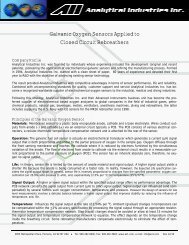
4.8 Mounting<br />
Every analyzer and monitor is equipped with a male dove tail bracket and<br />
triangular shaped thick metal wire stand secured to the rear of the enclosure.<br />
Tripod Wire Stand<br />
Secured between bumper feet on either side of the battery compartment is a<br />
triangular shaped thick metal wire stand that is hinged under the dove tail<br />
bracket secured at the opposite end of enclosure.<br />
Unsnap the triangular thick metal wire stand from between the bumper feet<br />
and pull it away from the enclosure to form a tripod which allows the device to<br />
sit upright on any flat surface<br />
5 Operation<br />
5.1 Principle of Operation<br />
The <strong>AII</strong>-<strong>3000</strong> <strong>Series</strong> <strong>Oxygen</strong> <strong>Analyzer</strong>s utilize an electrochemical galvanic fuel<br />
cell type oxygen sensor of the type that is extensively used to measure oxygen<br />
concentrations from 0% to 100% in gas streams. <strong>Oxygen</strong>, the fuel for this<br />
electrochemical transducer, diffusing into the sensor through a gas permeable<br />
membrane reacts chemically at the sensing electrode to produce an electrical<br />
current output proportional to the oxygen concentration in the gas phase. The<br />
sensor has an absolute zero meaning that when no oxygen is present to be<br />
chemically reacted the LCD displays 00.0 oxygen.<br />
The sensor’s signal output is linear over the entire range, remains virtually constant<br />
over the specified useful life and drops off sharply at the end. The sensor<br />
itself requires no maintenance and is simply replaced at the end of its useful life<br />
like a battery. Inasmuch as the sensor is a transducer in its own right, its expected<br />
life is not affected by whether the analyzer is ON or OFF.<br />
The relationship between the sensor’s signal and changes with the oxygen<br />
concentration is both proportional and linear, thus allowing single point calibration.<br />
Other factors that can affect the signal output are described in Section 5.2<br />
Application Considerations and Section 3 Safety Warnings which should be read<br />
before use.<br />
Dove Tail Bracket<br />
The male dove tail bracket is secured to the rear of the enclosure with two<br />
screws. The 1” female dove tail pole bracket (HRWR-1075) is an optional accessory<br />
that is commonly found in medical applications. The v-shaped male<br />
component simply slides into and out of the pole mounted female section.<br />
Historically, the expected life of galvanic fuel type sensors has been specified as<br />
“in air (20.9% O 2 ) at 25°C and 760mm Hg”. The actual life of any galvanic fuel<br />
type sensor is inversely affected by changes in the average oxygen concentration,<br />
temperature and pressure it is exposed to during its useful life. For example,<br />
the <strong>AII</strong>-11-60 sensor has a 60 months expected life in air (20.9% oxygen)<br />
at 25°C and ambient pressure, however, in a 100% oxygen atmosphere the<br />
expected life is 12.6 months [60mo/(100%/20.9%)].<br />
<strong>AII</strong>-<strong>3000</strong> <strong>Series</strong> <strong>Oxygen</strong> <strong>Analyzer</strong>s are battery powered by (2) AA alkaline batteries<br />
and controlled by a state-of-the-art microprocessor. The batteries provide<br />
enough power to operate the analyzer continuously for approximately 1,200<br />
hours. Both devices utilize a membrane type keypad for users to communicate<br />
commands to the microprocessor. The monitor is menu driven to accommodate<br />
the alarm functions. The digital electronics provide features such as system<br />
diagnostics, warning indicators, controls and an alarm capability for continuous<br />
monitoring that enhance both safety and effectiveness. The design criteria,<br />
quality program and performance features ensure reliable and accurate oxygen<br />
measurements.<br />
16<br />
17
5.2 Application Considerations<br />
Effect of Temperature<br />
All membrane clad electrochemical sensors are temperature dependent due to<br />
the expansion and contraction of the Teflon sensing membrane. As result more<br />
or less of the sample gas including oxygen to be reacted diffuses into the sensor.<br />
The oxygen sensor’s electrical current signal output varies linearly with<br />
oxygen concentration. The signal also varies with changes in ambient temperature.<br />
The temperature coefficient is typically 2.54% of the signal or reading per<br />
degree C change in temperature.<br />
The temperature dependent current signal output is compensated by using a<br />
resistor-thermistor network. With a proper resistor-thermistor network, the<br />
signal can be compensated to within +5% of the oxygen reading over the 5-<br />
45°C temperature range. This is the worse case situation when going from one<br />
extreme of the operating temperature range to the other. The error will be<br />
eliminated when the thermistor in the temperature compensation network and<br />
the electrolyte inside the sensor reach thermal equilibrium in approximately 45-<br />
60 minutes.<br />
Erroneous oxygen readings can result if the gases flowing over the<br />
sensing area of the sensor are not at ambient temperature. This occurs<br />
because the sensor is exposed to different temperatures. The sensing<br />
area of the sensor is o-ring sealed in the heated breathing circuit and the temperature<br />
compensation network at the rear of the sensor is exposed to ambient<br />
temperature.<br />
Effect of Pressure<br />
Electrochemical sensors actually measure the partial pressure, not the percentage,<br />
of oxygen in the gas stream they are exposed to. These sensors are accurate<br />
at any pressure provided the pressure is constant and the analyzer has<br />
been calibrated at the same pressure as the sample gas measured.<br />
For example, when moving an analyzer calibrated at sea level into the mountains<br />
causes the analyzer to display an decrease in the oxygen reading displayed.<br />
When if fact, the decrease in the reading displayed is not related to a<br />
change in the oxygen percentage but to the decrease in partial pressure<br />
(corresponding to the increase in total pressure) at altitude.<br />
Calibrate at the temperature and pressure (altitude) at which the analyzer<br />
will be operated.<br />
Effect of Humidity<br />
The analyzer is not affected by non-condensing relative humidity (RH). However,<br />
the use of a humidifier to introduce water vapor and increase the moisture<br />
level of the gas mixture does affect the oxygen concentration and the<br />
resultant reading displayed by the analyzer. The addition of water vapor increases<br />
the total pressure thereby diluting or decreasing the oxygen concentration<br />
of the gas mixture resulting in a lower oxygen reading.<br />
Effect of Condensation<br />
Excessive condensation collecting on the sensing area or the electrical connections<br />
at the rear of the sensors can adversely impact the performance of electrochemical<br />
sensors. Condensation blocks the diffusion path of oxygen into the<br />
sensor and can reduce the oxygen reading to 00.0 if the condensation covers<br />
the entire sensing area. Condensation on the electrical connections at the rear<br />
of the sensor can affect oxygen readings. Remedy either situation by shaking<br />
out the condensation and allowing the sensor to air dry.<br />
Erroneously characterized in many instances as a sensor failure, excessive condensation<br />
is remedied by gently wiping away the condensation with a soft cloth<br />
or simply allowing the sensor to air dry.<br />
Effect of Electromagnetic Radiation<br />
Tested over a 26 MHz to 1000 MHz electromagnetic field, the analyzer is susceptible<br />
at all frequencies tested except those between 930 and 990 MHz.<br />
Never operate the analyzer near equipment capable of emitting high<br />
levels of electromagnetic radiation. Do not continue to operate the analyzer<br />
if the reading becomes unstable.<br />
5.3 Calibration<br />
Calibrating the analyzer or monitor during normal operation involves the same<br />
precautions and procedures as those described in Sections 4.7 Start-up Calibration<br />
with the same cautions to review Sections 3 Safety Warnings and 5.2 Application<br />
Considerations.<br />
5.4 Sampling<br />
Assuming the START-UP instructions are followed and the tests are completed<br />
successfully the devices default to the SAMPLING mode.<br />
Never operate the analyzer if the reading is unstable or if a malfunction<br />
is suspected. If calibration is required as indicated herein, do not proceed<br />
until the analyzer is calibration successfully.<br />
18<br />
19
5.4.1 Flowing Gas Streams<br />
1. Place the sensing area of the sensor into the gas stream to be analyzed<br />
upstream of any humidification equipment.<br />
2. Assure that the flow rate of the gas stream does not exceed ten (10) liters<br />
per minute. Exceeding ten (10) liters per minute generates backpressure.<br />
3. Check the gas stream and particularly the mechanical connection for leaks<br />
that dilute the gas stream with ambient air.<br />
4. Assure there are no restrictions in the circuit downstream of the sensor<br />
that could generate backpressure on the sensor.<br />
5. Use the optional flow diverter along with the optional<br />
tee adapter and position the sensor vertically<br />
for optimum results, as shown right. The flow diverter<br />
avoids stagnation and facilitates the movement<br />
of gas to and from the sensing area of the<br />
sensor thereby producing a more accurate measurement<br />
of the gas stream to be measured.<br />
6. Install the tee-adapter in the breathing circuit.<br />
7. Screw the flow diverter to the sensor.<br />
8. Ensure the o-ring is lightly lubricated for ease of<br />
entry and a tight seal between the flow diverter and<br />
tee adapter.<br />
9. Insert the assembled flow diverter/sensor into the tee allowing air or<br />
100% oxygen (dry, non-humidified) to flow past the sensor at a rate of 5-<br />
8 liters per minute.<br />
10. Once the sensing area of the sensor is exposed to the gas stream allow<br />
approximately sixty (60) seconds for the reading to stabilize and observe<br />
the reading displayed by the LCD.<br />
11. Refer to Section 8.1 for a variety of accessories that provide a several<br />
methods of sampling flowing gas streams.<br />
5.4.2 Static Atmospheres<br />
Remove the flow diverter, not needed. Failure to remove the flow diverter will<br />
dramatically slow the response time of the sensor.<br />
Expose the sensing area of the sensor to the atmosphere allowing approximately<br />
sixty (60) seconds for the reading to stabilize and observe the<br />
reading displayed by the LCD.<br />
If placing the entire sensor inside the controlled atmosphere review<br />
Section 5.2 Application Consideration, Effect of Temperature.<br />
5.4.3 <strong>AII</strong>-<strong>3000</strong> AHC and MHC (Integral <strong>Oxygen</strong> Sensor)<br />
<strong>AII</strong>-<strong>3000</strong> AHC and MHC with their integral oxygen sensor requires connecting<br />
the ¼” tubing supplied (section 4.2.1 above) with the device to a ¼” hose<br />
barb attached to a pressure regulator controlling a source of gas flowing at less<br />
than 10 liters per minute.<br />
5.5 Alarms (<strong>AII</strong>-<strong>3000</strong> M/MHC):<br />
The monitor is equipped with user selectable HI and LO alarm set points which<br />
are displayed at the bottom of the LCD. Section 4.6 describes the operation<br />
and procedure for setting the alarms in detail.<br />
6 Maintenance<br />
Review Section 3 Safety Warnings and Section 7 Troubleshooting for<br />
guidelines on servicing the devices.<br />
6.1 Serviceability<br />
Do not open the main compartment of the analyzer, as it contains no serviceable<br />
parts inside. Never attempt to repair the analyzer or sensor by yourself as<br />
you may damage the analyzer which could void the warranty.<br />
6.1.2 Cleaning / Reuse Instructions<br />
Clean the device, oxygen sensor and accessories with a soft cloth dampened<br />
with either water or mild isopropyl alcohol solution (70% isopropyl alcohol<br />
solution in water), if necessary, before re-use. Allow the components to air-dry<br />
after cleaning.<br />
Note: The Home Care Kit is not intended for patient use, it is intended solely<br />
for confirming the O 2 concentration in <strong>Oxygen</strong> Concentrators. Accordingly, no<br />
cleaning instructions apply.<br />
6.2 Battery Replacement<br />
The analyzers and monitor are powered by two AA alkaline batteries with an<br />
approximate life of 1,200 hours. A low battery indicator circuit monitors the<br />
battery supply voltage and sends a signal directly to the LCD when the battery<br />
voltage reaches a preset level that activates the battery symbol in the LCD.<br />
The batteries are housed in a separate compartment located at the rear of the<br />
device and are accessible by sliding the removable cover.<br />
20 21
Initially this procedure can be somewhat difficult. Care should be taken<br />
not to damage the case when removing the battery compartment cover.<br />
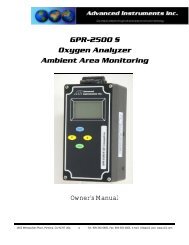
6.2.1 Procedure:<br />
1. Turn the device over so the<br />
shortest raised line on the battery<br />
compartment cover is pointing<br />
away from you.<br />
2. Lift the tripod wire stand up and<br />
away from the case.<br />
3. Grasp the case with both hands<br />
and using your thumbs press<br />
down firmly on the raised lines and push the battery compartment cover<br />
away from you.<br />
4. Locate the positive (+) and negative (-) terminals on the battery.<br />
5. Assure the battery contacts are clean.<br />
6. Align one battery’s positive (+) terminal with the corresponding (+) battery<br />
symbol molded into the case.<br />
7. Insert the battery into the compartment.<br />
8. Repeat with the remaining battery.<br />
9. Replace the battery compartment cover, make sure it snaps into position<br />
and is secured flush against the case. Replace the wire stand as required.<br />
10. Calibrate the device after replacing the batteries.<br />
6.3.2 Procedure <strong>AII</strong>-<strong>3000</strong> AHC and <strong>AII</strong>-<strong>3000</strong> MHC - Integral Sensor<br />
1. Tools required: small bladed screwdriver.<br />
2. Place the device face down on a flat surface.<br />
3. Remove the two (2) screws from the upper corners of the rear of the<br />
device.<br />
4. Move the tripod up, remove the battery compartment cover (see Battery<br />
Replacement) and remove the two (2) screws located on either side.<br />
5. Pull the rear section up ¼”-½”, turn it over and lay it next to the other<br />
section.<br />
6. Locate the white connector at the end of the four (4) wires running from<br />
the sensor (the cylinder with the white label) to the top of the PCB.<br />
7. With your left for finger and thumb, grasp the sides of the back end of the<br />
white connector where it is soldered to the PCB.<br />
8. With your right fore finger and thumb, grasp the sides of the section of<br />
the white connector where the four (4) wires from the sensor terminate.<br />
9. Separate the connector - hold the white connector section your left hand<br />
while gently pulling and wiggling the white connector section with your<br />
right hand until it unlocks.<br />
6.3 <strong>Oxygen</strong> Sensor Replacement<br />
The design of the electronics is intended for only the Analytical Industries Inc.<br />
<strong>AII</strong>-11-60 or <strong>AII</strong>-11-60-HC <strong>Oxygen</strong> Sensors. Use of a different oxygen sensor<br />
may result in an erroneous oxygen reading.<br />
NEVER - Open the oxygen sensor or probe the sensing surface, refer<br />
to Section 10 in the event the sensor should leak and someone comes<br />
in contact with the electrolyte from inside the sensor.<br />
6.3.1 Procedure <strong>AII</strong>-<strong>3000</strong> A and <strong>AII</strong>-<strong>3000</strong> M - External Sensor<br />
1. Disconnect the cable from the old sensor just as you disconnect a telephone<br />
jack from a wall plug.<br />
2. To connect the new sensor simply find and register the male plug at the<br />
end of the coiled cable and insert it into the mating female jack at the rear<br />
of the sensor until it mates or snaps into place.<br />
3. Calibrate the device after replacing the oxygen sensor.<br />
10. The oxygen sensor inserts into an adaptor (identified by a round recess<br />
with a cylindrical hose adapter in the center) that slides into grooves<br />
molded into the side of the case.<br />
11. Hold the rear section of the case down, grasp the square edges of the<br />
adaptor, lift up (lift straight up so as not to strip the grooves molded into<br />
the adaptor and case) and remove the adaptor and oxygen sensor as a<br />
single component.<br />
22 23
12. Once the adapter and old sensor have been removed from the case, hold<br />
the label of the sensor, again grasp the square edges of the adaptor and<br />
pull – to separate the old sensor from the adaptor.<br />
13. Remove the new oxygen sensor from the plastic shipping container.<br />
14. Install the new oxygen sensor by reversing steps 12 through 3.<br />
15. Calibrate the device after replacing the oxygen sensor.<br />
7 Troubleshooting<br />
If the recommended corrective action does not resolve the problem return the<br />
device to the factory for service.<br />
Symptom<br />
Corrective Action<br />
Symptom<br />
Reading displayed by LCD<br />
drifts during calibration<br />
<strong>Analyzer</strong> reading climbs after<br />
calibration in 100% dry oxygen<br />
when exposed to air<br />
20.9%<br />
Corrective Action<br />
Wait 5 minutes and repeat calibration with<br />
sensor placed on flat surface (not in your<br />
hand)<br />
Check integrity of gas delivery system<br />
Check sensor’s front o-ring seal<br />
Verify calibration gas in not humidified<br />
Remove moisture covering sensor<br />
Replace sensor, repeat calibration<br />
Allow the sensor to stabilize for 5 minutes in<br />
100% dry oxygen and recalibrate<br />
Device appears to be physically<br />
damaged<br />
No digital display when analyzer<br />
is turned ON<br />
Battery symbol on LCD display<br />
Turn device ON – if it successful passes<br />
START-UP TEST and calibrates – proceed.<br />
Install battery<br />
Replace battery<br />
Check battery polarity<br />
Check and/or clean battery contacts<br />
Replace battery and calibrate device<br />
After calibration in 100% dry<br />
oxygen, analyzer reading<br />
drifts more than 2% over 8<br />
hours<br />
Reading displayed by LCD<br />
does not change when oxygen<br />
level changes<br />
Check primary oxygen delivery device<br />
Replace sensor that is nearing the end of its<br />
useful life<br />
Replace sensor<br />
LCD display reads 00.0<br />
No response to keypad command<br />
Cannot turn device OFF<br />
Install sensor<br />
Check electrical connections<br />
Assure electrical connections are dry<br />
Replace battery<br />
Calibration routine in process – escape or<br />
wait until completed<br />
Reading does not stabilize or<br />
fluctuates erratically<br />
Relocate analyzer away source of radio frequency<br />
or electromagnetic radiation emissions.<br />
Tested over a 26 MHz to 1000 MHz<br />
electromagnetic field, the analyzer is susceptible<br />
at all frequencies tested except those<br />
between 930 and 990 MHz.<br />
Check sensor connection<br />
Check cable connection<br />
Wait 5 minutes and repeat calibration<br />
Replace sensor, repeat calibration<br />
Do not attempt to use the analyzer and<br />
return the analyzer for service.<br />
24 25
Symptom<br />
Corrective Action<br />
8 Specifications<br />
Reading displayed by LCD<br />
does not change when calibration<br />
control is adjusted<br />
Replace sensor<br />
Accuracy:<br />
Analysis:<br />
Area Classification:<br />
+2% of FS range under constant conditions<br />
0-100% oxygen<br />
General purpose<br />
Reading displayed by LCD is<br />
very low<br />
Alarms continuously activated<br />
Check sensor connection<br />
Check cable connection<br />
Replace sensor<br />
None – Normal operation, confirm set points<br />
Abnormal -<br />
Adjust alarm set points<br />
Remove moisture covering sensor<br />
Check sensor connection<br />
Check cable connection<br />
Check integrity of gas delivery system<br />
Check sensor’s front o-ring seal<br />
Verify calibration gas in not humidified<br />
Verify flow rate is 4-5 liters per minute<br />
Replace sensor<br />
Replace cable<br />
Alarms: A models – none; M models - User adjustable HI 1-100%<br />
and LO 0-99% alarms; 120 second alarm silence; HI<br />
alarm defeat for 100% O 2 measurements<br />
Calibration:<br />
Compensation:<br />
Air or 100% oxygen after 8 hours of continuous use.<br />
Temperature compensated<br />
Connections: A/M models: 1x16mm thread; HC models: Tubing 1/4”<br />
Controls:<br />
Soft touch keypad for ON/OFF and menu function<br />
Dimensions: 3.6 x 5.9 x 1.6”; weight 10 oz. (280 grams)<br />
Display: 3-1/2 digit backlit LCD 2.5” x 1.5”; resolution 0.1% O 2<br />
Flow Sensitivity: None between 0.2 to 10 liters per minute<br />
Humidity:<br />
LED Indicators:<br />
Linearity:<br />
Non-condensing 0-95% RH<br />
A models - none; M models - upon activation of alarms<br />
+ 1% under constant conditions<br />
Pressure:<br />
Power:<br />
Response Time:<br />
Sensitivity:<br />
Sensor:<br />
Expected Life:<br />
Storage Temp.:<br />
Temp. Range:<br />
Warm-up Time:<br />
Warranty:<br />
Inlet – (A/M) ambient, (HC) regulate; Vent - atmospheric<br />
2 AA Alkaline batteries; 1,200 hours continuous use<br />
90% of final FS reading in 9 seconds<br />
< 0.5% of FS range<br />
A/M models: <strong>AII</strong>-11-60 or HC models: <strong>AII</strong>-11-60-HC<br />
60 months in air at 25ºC and 1 atmosphere<br />
-20º to 60ºC (-4ºF to 140ºF) on intermittent basis<br />
5º to 45ºC (41ºF to 113ºF)<br />
None<br />
12 months analyzer; 12 months sensor<br />
26 27
Expected Sensor Life<br />
Considers the full range of the sensor’s signal, example 7-13 mV. <strong>Oxygen</strong> sensors<br />
are configured to meet the published, see preceding page, specification<br />
which distributes the overall sensor life as follows:<br />
- 60 months Expected Service Life (915,420 oxygen % hours)<br />
- 6 months Recommended Storage Life period (91,542 % oxygen hours)<br />
- 2 months margin of error<br />
Therefore, the Recommended Storage life period should not be considered a<br />
perishable shelf life. Operating at the specified parameters of oxygen concentration<br />
(air 20.9%), temperature (25⁰C/77⁰F) and pressure (1 atm/bar), the<br />
sensor will operate for approximately 68 months whether in storage or in use.<br />
The purpose of the Recommended Storage Life period is to ensure the user<br />
derives the Expected Life of 60 months (915,420 % oxygen hours) and does<br />
not lose the benefit of the warranty.<br />
Warranty<br />
The 12 month (183,084 % oxygen hours) warranty period (begins with shipment<br />
from the factory and is limited to the first claim submitted) is based on:<br />
8.1 Spare Parts & Accessories<br />
<strong>AII</strong>-<strong>3000</strong> A, <strong>AII</strong>-<strong>3000</strong> M <strong>AII</strong>-<strong>3000</strong> AHC, <strong>AII</strong>-<strong>3000</strong> MHC<br />
Spare Parts:<br />
Spare Parts:<br />
<strong>AII</strong>-11-60 <strong>Oxygen</strong> Sensor <strong>AII</strong>-11-60-HC <strong>Oxygen</strong> Sensor<br />
BATT-1008 Battery (2x) 1.5V AA BATT-1008 Battery (2x) 1.5V AA<br />
P-1087 Instructions for Use P-1087 Instructions for Use<br />
A-1162 PCB Assy Main A-1162 PCB Assy Main<br />
CABL-1006 Coil Cable TUBE-1019 7/32” OD Tubing 3’<br />
Optional Accessories - See opposing page<br />
CC-1072 Carrying Case<br />
28 29
9 Warranty<br />
Coverage<br />
Under normal operating conditions, the analyzer and sensors are warranted to<br />
be free of defects in materials and workmanship for the period specified in the<br />
current published specifications. To make a warranty claim, you must return the<br />
item properly packaged and postage prepaid to:<br />
<strong>Advanced</strong> <strong>Instruments</strong> Inc.<br />
2855 Metropolitan Place<br />
Pomona, Ca 91767 USA<br />
T: 909-392-6900, F: 909-392-3665<br />
E: sales-industrial@aii1.com, W: www.aii1.com<br />
<strong>Advanced</strong> <strong>Instruments</strong> in their sole discretion shall determine the nature of the<br />
defect. If the item is determined to be eligible for warranty we will repair it or,<br />
at our option, replace it at no charge to you. If we choose to repair your item,<br />
we may use new or reconditioned replacement parts of the same or upgraded<br />
design. This is the only warranty we will give and it sets forth all our responsibilities,<br />
there are no other express or implied warranties.<br />
The warranty begins with the date of shipment from <strong>Advanced</strong> <strong>Instruments</strong>, is<br />
limited to the first customer who submits a claim for a given serial number<br />
which must be in place and readable to be eligible for warranty and will not<br />
extend to more than one customer or beyond the warranty period under any<br />
conditions.<br />
Exclusions<br />
This warranty does not cover normal wear and tear; corrosion; damage while in<br />
transit; damage resulting from misuse or abuse; lack of proper maintenance;<br />
unauthorized repair or modification of the analyzer; fire; flood; explosion or<br />
other failure to follow the Owner’s Manual.<br />
Limitations<br />
<strong>Advanced</strong> <strong>Instruments</strong> shall not liable for losses or damages of any kind; loss of<br />
use of the analyzer; incidental or consequential losses or damages; damages<br />
resulting from alterations, misuse, abuse, lack of proper maintenance; unauthorized<br />
repair or modification of the analyzer.<br />
Service<br />
Contact us between 8:00am and 5:00pm PST Monday thru Thursday or before<br />
12:00pm on Friday. Trained technicians will assist you in diagnosing the problem<br />
and determining the appropriate course of action.<br />
30<br />
10 Material Safety Data Sheet (MSDS)<br />
Product name<br />
Exposure<br />
Ingredients<br />
Properties<br />
Flash Points<br />
Reactivity<br />
Health Hazard<br />
Symptoms<br />
Protection<br />
Precautions<br />
Action KOH<br />
Leak<br />
Electrochemical Galvanic Fuel Cell <strong>Oxygen</strong> Sensor<br />
Sealed device with protective coverings, normally no hazard<br />
Carcinogens - none; Potassium Hydroxide (KOH), Lead (Pb)<br />
Completely soluble in H2O; evaporation similar to H2O<br />
Not applicable, non-flammable<br />
Stable; avoid strong acids, emits fumes when heated<br />
KOH entry via ingestion - harmful or fatal if swallowed;<br />
eye - corrosive, possible loss of vision;<br />
skin contact - corrosive, possible chemical burn.<br />
Liquid inhalation is unlikely.<br />
Lead - known to cause birth defects, contact unlikely<br />
Eye contact - burning sensation; skin contact - slick feeling<br />
Ventilation - none; eye - safety glasses; hands - gloves<br />
Do not remove Teflon and PCB coverings; do not probe with<br />
sharp objects; avoid contact with eyes, skin and clothing.<br />
Use rubber gloves, safety glasses and H2O and flush all<br />
surfaces repeatedly with liberal amounts of H2O<br />
10.1 Disposal<br />
<strong>Oxygen</strong> sensors and batteries should be disposed of in accordance with local<br />
regulations for batteries.<br />
WEEE regulations prohibit electronic products including the Helium<br />
and environmental sensors from being placed in household<br />
trash bins.<br />
Electronic products should be disposed of in accordance with local<br />
regulations.<br />
31