GPR-18 MS ATEX Explosion Proof PPB Oxygen Analyzer.
GPR-18 MS ATEX Explosion Proof PPB Oxygen Analyzer.
GPR-18 MS ATEX Explosion Proof PPB Oxygen Analyzer.
- No tags were found...

Create successful ePaper yourself
Turn your PDF publications into a flip-book with our unique Google optimized e-Paper software.
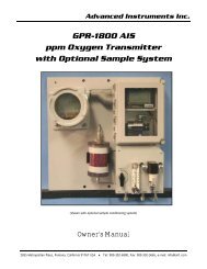
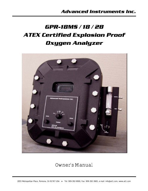
Advanced Instruments Inc.<strong>GPR</strong>-<strong>18</strong><strong>MS</strong> / <strong>18</strong> / 28<strong>ATEX</strong> Certified <strong>Explosion</strong> <strong>Proof</strong><strong>Oxygen</strong> <strong>Analyzer</strong>Owner’s Manual2855 Metropolitan Place, Pomona, CA 91767 USA ♦ Tel: 909-392-6900, Fax: 909-392-3665, e-mail: info@aii1.com, www.aii1.com
Advanced Instruments Inc.Table of ContentsIntroduction 1Quality Control Certification 2Safety 3Features & Specifications 4Operation 5Maintenance 6Spare Parts 7Troubleshooting 8Warranty 9Material Safety Data Sheets 10Declaration of Conformity<strong>ATEX</strong> Certificate (English) <strong>18</strong><strong>MS</strong> / <strong>18</strong> / 28<strong>ATEX</strong> Certificate (French) <strong>18</strong><strong>MS</strong> / <strong>18</strong> / 28CE Certificate EN 61326 Minimum ImmunityCE Certificate EN 61010-1 Safety Requirements<strong>ATEX</strong> Certificate Manufacturer’s Enclosure & ControllersInstructions Installation & Maintenance Enclosure & Controllers<strong>ATEX</strong> Certificate & Instructions Flame ArrestorsInstructions <strong>Explosion</strong> <strong>Proof</strong> Electrical ConnectionsDrawingsAppendix AAppendix BAppendix BfAppendix CAppendix DAppendix EAppendix FAppendix GAppendix HAppendix IThe appendices referenced above are an integral part of the documentation, installation and maintenance of this <strong>ATEX</strong> certifiedoxygen analyzer. It is important that users review these documents before proceeding.2
Advanced Instruments Inc.1 IntroductionYour new <strong>ATEX</strong> Certified <strong>Explosion</strong> <strong>Proof</strong> <strong>Oxygen</strong> <strong>Analyzer</strong> is a precision device designed to give you years of use. It has beendesigned to incorporate several types of oxygen sensors enabling user’s to select an analysis range appropriate for theirapplication with the confidence of an <strong>ATEX</strong> certified analyzer system. Analysis ranges available with selected oxygen sensors:<strong>GPR</strong>-<strong>18</strong><strong>MS</strong> analyzes oxygen levels from 10 ppb (parts per billion) to 1,000 ppm (parts per million) and features the new “Pico-Ion” Sensor Technology developed exclusively by Advanced Instruments Inc.<strong>GPR</strong>-<strong>18</strong> analyzes oxygen levels from 100 ppb to 1% (10,000 ppm) and features the advanced galvanic type ppm oxygen sensor.<strong>GPR</strong>-28 analyzes oxygen levels from 0.05% (500 ppm) to 95% and features the advanced galvanic type percent oxygen sensor.Specifications of the individual analyzers and discussion of the sensors can be found in sections 4 and 5 .These analyzers is designed to measure the oxygen concentration in inert gases, gaseous hydrocarbons, hydrogen and a varietyof gas mixtures. The galvanic sensors can be configured for measuring 0-100% oxygen concentration in CO2 and acid gases. Toobtain maximum performance from your new oxygen analyzer, please read and follow the guidelines provided in this Owner’sManual.Every effort has been made to select the most reliable state of the art materials and components; and, to design the analyzerfor superior performance and minimal cost of ownership. This analyzer was tested thoroughly by the manufacturer prior toshipment for best performance.However, modern electronic devices do require service from time to time. The warranty included herein plus a staff of trainedprofessional technicians to quickly service your analyzer is your assurance that we stand behind every analyzer sold.The serial number of this analyzer may be found on the inside the analyzer. You should note the serial number in the spaceprovided and retains this Owner’s Manual as a permanent record of your purchase, for future reference and for warrantyconsiderations.Serial Number: _______________________Advanced Instruments Inc. appreciates your business and pledges to make every effort to maintain the highest possible qualitystandards with respect to product design, manufacturing and service.3
2 Quality Control CertificationAdvanced Instruments Inc.Date: Customer: Order No.: PassModel: ( ) <strong>GPR</strong>-<strong>18</strong><strong>MS</strong> <strong>Explosion</strong> <strong>Proof</strong> ppm O2 <strong>Analyzer</strong> S/N ______________________( ) <strong>GPR</strong>-<strong>18</strong> <strong>Explosion</strong> <strong>Proof</strong> ppm O2 <strong>Analyzer</strong> S/N ______________________( ) <strong>GPR</strong>-28 <strong>Explosion</strong> <strong>Proof</strong> O2 <strong>Analyzer</strong> S/N ______________________Sensor: ( ) <strong>GPR</strong>-12-2000<strong>MS</strong> ppm <strong>Oxygen</strong> Sensor S/N ______________________( ) <strong>GPR</strong> or ( ) XLT-12-333 ppm <strong>Oxygen</strong> Sensor S/N ______________________( ) <strong>GPR</strong>-11-32 or ( ) XLT-11-24 <strong>Oxygen</strong> Sensor S/N ______________________Approvals:Accessories:Configuration:<strong>ATEX</strong> certified Ex d IIB T6 or Ex d IIB+H2; certificate #INERIS07<strong>ATEX</strong>0025XEN 61326 Minimum Immunity TestEN 61010-1:2001 Low Voltage Directive (see Appendix A, B, C, D)Owner’s Manual5/16 Open end wrenchA-1107-M PCB Assembly Main / DisplayA-1106-M PCB Assembly Power / RelayRange: ( ) <strong>GPR</strong>-<strong>18</strong><strong>MS</strong> 0-1 ppm, 0-10 ppm, 0-100 ppm, 0-1000 ppm( ) <strong>GPR</strong>-<strong>18</strong> 0-10 ppm, 0-100 ppm, 0-1000 ppm, 0-25% (air calibration only)( ) <strong>GPR</strong>-28 0-1%, 0-5%, 0-10%, 0-25%Wetted parts: stainless steel ( ) Manual flow and bypass valves, flow indicator( ) Manual flow meter (with integral metering valve)Standard power: ( ) 100/110 VAC or ( ) 220/240 VACHeater system:( ) 100/110 VAC or ( ) 220/240 VAC; controller set at 85° FTest – Electronics:Test – Gas:Final:LED indicators: range, alarms4-20mA offsetAlarm relays activate/deactivate with changes in O 2 concentrationAnalog signal output 0-1V and 4-20mARange ID contacts (optional)Baseline drift on zero gas < ± 2% F.S. over 24 hour periodNoise level < ± 1.0% F.S.Span adjustment within 10-50% F.S.Peak to peak over / under shoot < 0.5% F.S.Overall inspection for physical defects; place SAMPLE/BYPASS valve in BYPASS positionOptions:Notes:4
3 General Safety & InstallationAdvanced Instruments Inc.SafetyThis section summarizes the basic precautions applicable to all analyzers. Additional precautions specific to individual analyzerare contained in the following sections of this manual. To operate the analyzer safely and obtain maximum performance followthe basic guidelines outlined in this Owner’s Manual.Caution: This symbol is used throughout the Owner’s Manual to Caution and alert the user to recommended safety and/oroperating guidelines.Danger: This symbol is used throughout the Owner’s Manual to identify sources of immediate Danger such as the presence ofhazardous voltages.Read Instructions: Before operating the analyzer read the instructions.Retain Instructions: The safety precautions and operating instructions found in the Owner’s Manual should be retained forfuture reference.Heed Warnings Follow Instructions: Follow all warnings on the analyzer, accessories (if any) and in this Owner’s Manual.Observe all precautions and operating instructions. Failure to do so may result in personal injury or damage to the analyzer.Heat: Situate and store the analyzer away from sources of heat.Liquid and Object Entry: The analyzer should not be immersed in any liquid. Care should be taken so that liquids are notspilled into and objects do not fall into the inside of the analyzer.Handling: Do not use force when using the switches and knobs. Before moving your analyzer be sure to disconnect thewiring/power cord and any cables connected to the output terminals located on the analyzer.MaintenanceServiceability: Except for replacing the oxygen sensor, there are no parts inside the analyzer for the operator to service.Only trained personnel with the authorization of their supervisor should conduct maintenance.<strong>Oxygen</strong> Sensor: DO NOT open the sensor. The sensor contains a corrosive liquid electrolyte that could be harmful if touchedor ingested, refer to the Material Safety Data Sheet contained in this Owner’s Manual. Avoid contact with any liquid or crystaltype powder in or around the sensor or sensor housing, as either could be a form of electrolyte. Leaking sensors should bedisposed of in accordance with local regulations.Troubleshooting: Consult the guidelines in section 8 for advice on the common operating errors before concluding that youranalyzer is faulty. Do not attempt to service the analyzer beyond those means described in this Owner’s Manual.Do not attempt to make repairs by yourself as this will void the warranty, as detailed by section 9, and may result in electricalshock, injury or damage. All other servicing should be referred to qualified service personnel.Cleaning: The analyzer should be cleaned only as recommended by the manufacturer. Wipe off dust and dirt from the outsideof the unit with a soft damp cloth then dry immediately. Do not use solvents or chemicals.Nonuse Periods: Disconnect the power when the analyzer is left unused for a long period of time.InstallationGas Sample Stream: Ensure the gas stream composition of the application is consistent with the specifications and review theapplication conditions before initiating the installation. Consult the factory to ensure the sample is suitable for analysis.Contaminant Gases: A gas scrubber and flow indicator with integral metering valve are required upstream of the of theanalyzer to remove interfering gases such as oxides of sulfur and nitrogen or hydrogen sulfide that can produce false readings,reduce the expected life of the sensor and void the sensor warranty if not identified at time of order placement. Installation of asuitable scrubber is required to remove the contaminant from the sample gas to prevent erroneous analysis readings and5
Advanced Instruments Inc.damage to the sensor or optional components. Consult the factory for recommendations concerning the proper selection andinstallation of components.Expected Sensor Life: With reference to the publish specification located in section 4 of this manual, the expected life of alloxygen sensors is predicated on oxygen concentration (< 1000 ppm or air), temperature (77°F/25°C) and pressure (1atmosphere) in “normal” applications. As a rule of thumb sensor life is inversely proportional to changes in the parameters.Deviations are outside the specifications and will affect the life of the sensor, with respect to Pico-Ion sensors avoid exposure tooxygen levels above 1000 ppm. Failure to do will result in damage to the sensor.Accuracy & Calibration: Refer to section 5 Operation, Calibration. <strong>Analyzer</strong>s equipped with Pico-Ion oxygen sensors have amaximum range of 0-1000 ppm reflecting its high signal output capability, DO NOT CALIBRATE THE <strong>GPR</strong>-<strong>18</strong><strong>MS</strong> WITH AIR.Materials: Assemble the necessary zero, purge and span gases and optional components such as valves, coalescing orparticulate filters, and, pumps as dictated by the application; stainless steel tubing is essential for maintaining the integrity ofthe gas stream for ppm and percentage range (above or below ambient air) analysis; hardware for mounting.Operating Temperature: The sample must be sufficiently cooled before it enters the analyzer and any optional components.A coiled 10 foot length of ¼” stainless steel tubing is sufficient for cooling sample gases as high as 1,800ºF to ambient. Themaximum operating temperature is 45º C on an intermittent basis unless the user is willing to accept a reduction in expectedsensor life – refer to analyzer specification - where expected sensor life is specified at an oxygen concentration less than 1000ppm oxygen for ppm analyzers and air (20.9% oxygen) for percent analyzers, but in all instances at 25°C and 1 atmosphere ofpressure. Expected sensor varies inversely with changes in these parameters.Pressure & FlowAll electrochemical oxygen sensors respond to partial pressure changes in oxygen. The sensors are equally capable of analyzingthe oxygen content of a flowing sample gas stream or monitoring the oxygen concentration in ambient air (such as a confinedspace such in a control room or an open area such as a landfill or bio-pond). The following is applicable to analyzersequipped with galvanic oxygen sensors, <strong>GPR</strong>-<strong>18</strong> and <strong>GPR</strong>-28. With respect to analyzers equipped with Pico-Ionoxygen sensors, <strong>GPR</strong>-<strong>18</strong><strong>MS</strong> refer to the analyzer’s specifications in section 4.<strong>Analyzer</strong>s designed for in-situ ambient or area monitoring have no real inlet and vent pressure because the sensor is exposeddirectly to the sample gas and intended to operate at atmospheric pressure, however, slightly positive pressure has minimaleffect on accuracy.Inlet Pressure: <strong>Analyzer</strong>s designed for flowing samples under positive pressure or pump vacuum (for samples at atmosphericor slightly negative atmospheres) that does not exceed 14” water column are equipped with bulkhead tube fitting connectionson the side of the unit (unless otherwise indicated, either fitting can serve as inlet or vent) and are intended to operate atpositive pressure regulated to between 5-30 psig although the rating of the fitting itself is considerably higher. Caution: If theanalyzer is equipped with an optional H2S scrubber, inlet pressure must not exceed 30 psig.Outlet Pressure: In positive pressure applications the vent pressure must be less than the inlet, preferably atmospheric.Sample systems and flowing gas samples are generally required for applications involving oxygen measurements at a pressureother than ambient air. In these situations, the use of stainless steel tubing and fittings is critical to maintaining the integrity ofthe gas stream to be sampled and the inlet pressure must always be higher than the pressure at the outlet vent which isnormally at atmospheric pressure. Flow Through Configuration: The sensor is exposed to sample gas that must flow or bedrawn through metal tubing inside the analyzer. The internal sample system includes 1/8” compression inlet and vent fittings, astainless steel sensor housing with an o-ring seal to prevent the leakage of air and stainless steel tubing.Flow rates of 1-5 SCFH cause no appreciable change in the oxygen reading. However, flow rates above 5 SCFH generatebackpressure and erroneous oxygen readings because the diameter of the integral tubing cannot evacuate the sample gas atthe higher flow rate. The direction the sample gas flows is not important, thus either tube fitting can serve as the inlet or vent –just not simultaneously.A flow indicator with an integral metering valve upstream of the sensor is recommended as a means of controlling the flow rateof the sample gas. A flow rate of 2 SCFH or 1 liter per minute is recommended for optimum performance.6
Advanced Instruments Inc.Application Pressure - Positive: A flow indicator with integral metering valve positioned upstream of the sensor isrecommended for controlling the sample flow rate between 1-5 SCFH. To reduce the possibility of leakage for low ppmmeasurements, position a metering needle valve upstream of the sensor to control the flow rate and position a flow indicatordownstream of the sensor. If necessary, a pressure regulator (with a metallic diaphragm is recommended for optimumaccuracy, the use of diaphragms of more permeable materials may result in erroneous readings) upstream of the flow controlvalve should be used to regulate the inlet pressure between 5-30 psig.Caution: If the analyzer is equipped with a H2S scrubber as part of an optional sample conditioning system, inlet pressuremust not exceed 30 psig.Application Pressure - Atmospheric or Slightly Negative: For accurate ppm range oxygen measurements, an optionalexternal sampling pump should be positioned downstream of the sensor to draw the sample from the process, by the sensorand out to atmosphere. A flow meter is generally not necessary to obtain the recommended flow rate with most samplingpumps.Caution: If the analyzer is equipped with an optional flow indicator with integral metering valve or a metering flow controlvalve upstream of the sensor - open the metering valve completely to avoid drawing a vacuum on the sensor and placing anundue burden on the pump. If pump loading is a consideration, a second throttle valve on the pump’s inlet side may benecessary to provide a bypass path so the sample flow rate is within the above parameters.Recommendations to avoid erroneous oxygen readings and damaging the sensor:‣ Do not place your finger over the vent (it pressurizes the sensor) to test the flow indicator when gas is flowing to thesensor. Removing your finger (the restriction) generates a vacuum on the sensor and may damage the sensor (thus voidingthe sensor warranty).‣ Assure there are no restrictions in the sample or vent lines‣ Avoid drawing a vacuum that exceeds 14” of water column pressure – unless done gradually‣ Avoid excessive flow rates above 5 SCFH which generate backpressure on the sensor.‣ Avoid sudden releases of backpressure that can severely damage the sensor.‣ Avoid the collection of liquids or particulates on the sensor, they block the diffusion of oxygen into the sensor - wipe away.‣ If the analyzer is equipped with an optional integral sampling pump (positioned downstream of the sensor) and a flowcontrol metering valve (positioned upstream of the sensor), completely open the flow control metering valve to avoiddrawing a vacuum on the sensor and placing an undue burden on the pump.Moisture & Particulates: Installation of a suitable coalescing or particulate filter is required to remove condensation, moistureand/or particulates from the sample gas to prevent erroneous analysis readings and damage to the sensor or optionalcomponents. Moisture and/or particulates do not necessarily damage the sensor, however, collection on the sensing surface canblock or inhibit the diffusion of sample gas into the sensor resulting in a reduction of sensor signal output – and the appearanceof a sensor failure when in fact the problem is easily remedied by blowing on the front of the sensor. Consult the factory forrecommendations concerning the proper selection and installation of components.Moisture and/or particulates generally can be removed from the sensor by opening the sensor housing and either blowing onthe sensing surface or gently wiping or brushing the sensing surface with damp cloth. Caution: Minimize the exposure of ppmsensors to air during this cleaning process. Air calibration followed by purging with zero or a gas with a low ppm oxygenconcentration is recommended following the cleaning process. Moisture and/or particulates generally can be removed from thesample system by flowing the purge gas through the analyzer at a flow rate of 4.5-5 SCFH for an hour.Mounting: The analyzer is approved for indoor use, outdoor use requires optional enclosures, consult factory. Mount asrecommended by the manufacturer.Gas Connections: Inlet and outlet vent gas lines for ppm analysis require 1/8” or ¼” stainless steel compression fittings; hardplastic tubing with a low permeability factor can be used percentage range measurements.Power: Supply power to the analyzer only as rated by the specification or markings on the analyzer enclosure. The wiring thatconnects the analyzer to the power source should be installed in accordance with recognized electrical standards. Ensure that isproperly grounded and meets the requirements for area classification. Never yank wiring to remove it from a terminalconnection. AC powered analog analyzers consume 5 watts. Optional 110V and 220V heaters AC powered heaters consume anadditional 100-150 watts.7
4 Features & SpecificationsAdvanced Instruments Inc.8
Advanced Instruments Inc.9
Advanced Instruments Inc.5 OperationPrinciple of OperationThis <strong>ATEX</strong> Certified <strong>Explosion</strong> <strong>Proof</strong> <strong>Oxygen</strong> <strong>Analyzer</strong> is a precision device designed to give you years of use. It has beendesigned to incorporate several types of oxygen sensors enabling user’s to select an analysis range appropriate for theirapplication with the confidence of an <strong>ATEX</strong> certified analyzer system. Analysis ranges available with selected oxygen sensors:<strong>GPR</strong>-<strong>18</strong><strong>MS</strong> analyzes oxygen levels from 10 ppb (parts per billion) to 1,000 ppm (parts per million) and features the new “Pico-Ion” Sensor Technology developed exclusively by Advanced Instruments Inc.<strong>GPR</strong>-<strong>18</strong> analyzes oxygen levels from 100 ppb to 1% (10,000 ppm) and features the advanced galvanic type ppm oxygen sensor.<strong>GPR</strong>-28 analyzes oxygen levels from 0.05% (500 ppm) to 95% and features the advanced galvanic type percent oxygen sensor.Breakthrough Sensor Technology:A breakthrough sensor technology measures the partial pressure of oxygen from less than 10 ppb to 1000 ppm level in inertgases, gaseous hydrocarbons, helium, hydrogen and mixed gas streams. The “Pico-Ion” sensor design and chemistry have beencombined to produce a significant advancement in oxygen sensor technology.10
Advanced Instruments Inc.<strong>Oxygen</strong>, the fuel for these electrochemical transducers, reacts chemically at the sensing electrode to produce an electricalcurrent output proportional to the oxygen concentration in the gas phase. The sensor’s signal output is linear over all fourranges and remains virtually constant over its useful life. The sensor requires no maintenance or electrolyte addition and iseasily and safely replaced at the end of its useful life.Advanced Galvanic ppm Sensor TechnologyThe sensors function on the same principle and are specific for oxygen. They measure the partial pressure of oxygen from lowppm to 1% levels in inert gases, gaseous hydrocarbons, helium, hydrogen, mixed gases, acid gas streams and ambient air.Proprietary advancements in design and chemistry add significant advantages to an extremely versatile oxygen sensingtechnology. Sensors for low ppm analysis recover from air to ppm levels in minutes, exhibit longer life, excellent compatibilitywith CO 2 and acid gases (XLT series) and reliable quality giving them a significant advantage over the competition.Advanced Galvanic Percent Sensor TechnologyThe sensors function on the same principle and are specific for oxygen. They measure the partial pressure of oxygen from lowpercent levels (0.05%) to 100% levels in inert gases, gaseous hydrocarbons, helium, hydrogen, mixed gases, acid gas streamsand ambient air.Proprietary advancements in design and chemistry add significant advantages to an extremely versatile oxygen sensingtechnology. Extending the expected life of our new generation of percentage range sensors now range to five and ten yearswith faster response times and greater stability. Another significant development involves the first galvanic oxygen sensorcapability of continuous oxygen purity measurements and expanding the operating temperature range from -40°C to 50°C,excellent compatibility with CO 2 and acid gases (XLT series) and reliable quality giving them a significant advantage over thecompetition.11
Advanced Instruments Inc.ElectronicsThe signal generated by the sensor is processed by state of the art low design and integrated circuits. The first stage amplifiesthe signal. The second stage eliminates the low frequency noise. The third stage employs a high frequency filter andcompensates for signal output variations caused by ambient temperature changes. The result is a very stable signal. Sampleoxygen is analyzed very accurately. Response time of 90% of full scale is less than 10 seconds (actual experience may vary dueto the integrity of sample line connections, dead volume and flow rate selected) on all ranges under ambient monitoringconditions. Sensitivity is typically 0.5% of full scale low range. <strong>Oxygen</strong> readings may be recorded by an external device via anisolated 4-20mA and 0-1V signal output jack.Sample oxygen is analyzed very accurately. Overall performance is enhanced by an optional temperature controlled heatersystem that controls the temperature around the sensor. Response time of 90% of full scale is less than 20 seconds on the 0-1ppm range and on higher ranges (actual experience may vary due to the integrity of sample line connections, dead volume andflow rate selected).Power for the on-line analyzers is supplied by an integral power supply. Connections of the appropriate AC line voltage are hardwired to screw type terminal blocks. Power requirements related to 100/110VAC and 220/230VAC heaters must be specified atorder placement.Sample SystemsThe sample must be properly presented to the sensor to ensure an accurate measurement. The <strong>GPR</strong>-<strong>18</strong><strong>MS</strong> and <strong>GPR</strong>-<strong>18</strong> aredesigned with a sample system consisting of stainless steel and glass wetted parts,a uniquely designed leak tight sensorhousing that has been proven capable of less than 1 ppb oxygen measurements (using the Pico-Ion sensor) and a bypasssample system that complements the performance (fast recovery from exposure to high oxygen levels) capabilities of the sensorand enables the user to isolate the sensor from exposure to high oxygen concentrations which results is a substantial increase isuser productivity.This bypass feature has two important features: one, the sensor can be isolated from exposure to high oxygen levels whenchanging sample lines, during transport and during standby intervals; and, two, it enables the user to purge newly connectedgas lines of the oxygen trapped inside. The result is an analyzer that comes on-line at ppb or ppm levels in a matter of minutesand provides users with a significant increase in productivity.12
Advanced Instruments Inc.<strong>GPR</strong>-<strong>18</strong><strong>MS</strong><strong>GPR</strong>-<strong>18</strong>The advantages of the bypass sample system include:‣ Supplying the analyzer with the sensor it was qualified with.‣ Isolating the sensor during transport, calibration and maintenance intervals when changing gas line connections.‣ Isolating the sensor from exposure to high oxygen levels during upset conditions which extends sensor life.‣ Purging the air (or high oxygen levels above 1,000 ppm) trapped in the gas lines following a process upset.<strong>GPR</strong>-28 is designed with a sample system that enables the user to control the flow rate via a flow meter positioned upstreamof the sensor. The sample must be properly presented to the sensor to ensure an accurate measurement. The sensor isexposed to sample gas that must flow or be drawn through the analyzer’s internal sample system.Advanced Instruments Inc. offers a full line of sample handling, conditioning and expertise to meet your applicationrequirements. Contact us at 909-392-6900 or e-mail us at info@aii1.com13
Advanced Instruments Inc.Accuracy & CalibrationSingle Point Calibration: As previously described the galvanic oxygen sensor generates an electrical current proportional tothe oxygen concentration in the sample gas.Absolute Zero: In the absence of oxygen the sensorexhibits an absolute zero, e.g. the sensor does notgenerate a current output in the absence of oxygen.Given these linearity and absolute zero properties, singlepoint calibration is possible.Pressure: Because sensors are sensitive to the partialpressure of oxygen in the sample gas their output is afunction of the number of molecules of oxygen 'per unitvolume'. Readouts in percent are permissible only whenthe total pressure of the sample gas being analyzedremains constant. The pressure of the sample gas andthat of the calibration gas(es) must be the same (reality< 1-2 psi).Temperature: The rate oxygen molecules diffuse intothe sensor is controlled by a Teflon membrane otherwiseknown as an 'oxygen diffusion limiting barrier' and all diffusion processes are temperature sensitive, the fact the sensor'selectrical output will vary with temperature is normal. This variation is relatively constant 2.5% per ºC.A temperature compensation circuit employing a thermistor offsets this effect with an accuracy of better than +5% (over theentire Operating Range of the analyzer) and generates an output function that is independent of temperature. There is no errorif the calibration and sampling are performed at the same temperature or if the measurement is made immediately aftercalibration. Lastly, small temperature variations of 10-15º produce < 1% error.Accuracy: In light of the above parameters, the overall accuracy of an analyzer is affected by two types of errors: 1) thoseproducing 'percent of reading errors', illustrated by Graph A below, such as +5% temperature compensation circuit, tolerancesof range resistors and the 'play' in the potentiometer used to make span adjustments and 2) those producing 'percent of fullscale errors', illustrated by Graph B, such as +1-2% linearity errors in readout devices, which are really minimal due to today'stechnology and the fact that other errors are 'spanned out' during calibration. Graph C illustrates these 'worse case'specifications that are typically used to develop an transmitter's overall accuracy statement of < 1% of full scale at constanttemperature or < 5% over the operating temperature range. QC testing is typically < 0.5% prior to shipment.Example: As illustrated by Graph A any error, play in the multi-turn span pot or the temperature compensation circuit, duringa span adjustment at 20.9% (air) of full scale range would be multiplied by a factor of 4.78 (100/20.9) if used formeasurements of 95-100% oxygen concentrations. Conversely, an error during a span adjustment at 100% of full scale range isreduced proportionately for measurements of lower oxygen concentrations.Refer to the Calibration section for additional information.14
Advanced Instruments Inc.Mounting the <strong>Analyzer</strong>The oxygen analyzer consists of two PCB assemblies, sensor housing and sample system valves. An optional temperaturecontrolled heater system enhances stability during low ppm measurements. In standard configuration the alarm controls areintegral to prevent tampering, however, as illustrated below the alarm controls can be accessed externally with approvedactuators.These components are packaged in 13.250x17.250x10.750” wall mount enclosure with <strong>ATEX</strong> certification and NEMA 4/7 rating.Designed for mounting on a flat vertical surface approximately 5 feet above the floor by bolting the mounting feet attached tothe rear of the enclosure. The user is responsible for selecting the appropriate bolts to support at least 80 pounds.15
Advanced Instruments Inc.Procedure:1. Disconnect the AC power source before servicing the analyzer.2. Insert the power cable through the user supplied approved conduit fitting on the left side of the analyzer.3. Insert the output cable(s) through the user supplied approved conduit fittings on the right side of the analyzer.4. Strip the ends of the wires approximately ¼ inch.5. Remove the safety cover plate.6. Loosen the terminal screws, insert the bare wire into the appropriate terminals and re-tighten with a small bladedscrewdriver.7. Note: If equipped with the optional temperature controlled heater system, the necessary wiring has been installed at thefactory and no additional connections are required. The power connection services both the analyzer electronics andtemperature controlled heater system.8. Caution: Connect the power ground directly to the ground terminal on the inside of the analyzer case.9. Replace the safety cover plate.10. Pack and seal the power and interconnection wiring as described in Appendix A.11. Establish power as directed below.17
Advanced Instruments Inc.AlarmsThe analyzer is equipped with two user adjustable alarms located on the interior panel attached to the front door. Whenactivated the alarms trigger SPDT Form C, normally closed, non-latching relays @ 5A, 30VDC or 240VAC resistive. The alarmsare fully adjustable by the two potentiometers accessible from the auxiliary panel on the inside of the door with a small bladedscrewdriver. Optionally, alarm control actuators can be mounted externally as illustrated in the Mounting the <strong>Analyzer</strong> sectionabove.Note: Fail safe alarm configuration - connect positive lead to NO and negative to the C, common or neutral. To connect to anactive relay, connect the live cable to the common terminal C and the secondary cable to the normally open NO terminal. Tobreak the connection upon relay activation, connect the secondary cable to the normally closed NC terminal.Power Fail AlarmA dry contact rated at 30VDC @ 1A is provided as a power failure alarm. The contact is normally closed but opens when thepower to the analyzer is switched off or interrupted. Connect the lead wires from the external recording device to the malephone plug supplied with analyzer.Sensor Fail AlarmA 5V output with negative ground is provided when the sensor is operational. The output is 0V when the sensor fails and itsoutput goes to zero. Note: Adjusting the ZERO OFFSET to .000 activates the Sensor Failure Alarm characterized by amomentary spike in the trend analysis. To avoid the spike set the ZERO OFFSET to .001Caution: The sensor failure alarm becomes active when the display indicates ‘000’ on any range of the analyzer. To verify the‘sensor failure’ condition, advance the range switch to the lowest (most sensitive) range available. If the display continues toindicate ‘000’ or a negative number, replace the sensor.Range ID OutputA voltage output corresponding to each range is provided. The output of the highest range (normally CAL) is 5V and theremaining three ranges 4V, 3V and 2V for the low range.Signal OutputsThe analyzer provides an isolated 4-20mA signal output and a 0-1V full scale signal output for external recording devices. Theintegral IC on the main PCB converts the 0-1V signal with negative ground to a 4-20mA fully isolated signal. A finer adjustmentof the zero offset of the 4-20mA converter can be provided by a potentiometer, R99, mounted on the main PCB Assembly.Consult factory for instructions. Caution: The integral 4-20mA converter is internally powered and does not require externalpower. DO NOT supply any voltage to either of the two terminals of the 4-20mA converter.Temperature ControllerIf the optional the temperature controlled heater system is installed, access it by opening the front door. This unit is a PIDcontroller that operates between 0-99°F. The controller is programmed to maintain the temperature at 75-85°F. Caution: Donot change this setting. A higher temperature setting may drastically reduce sensor life and possibly cause damage to theelectronic circuitry of both the controller and the analyzer.When power is applied to the temperature controller, the controller tunes itself to eliminate and/or minimize the over/undershoot of temperature from the setpoint. It is recommended that at initial start-up, when replacing the oxygen sensor or whentrouble shooting; turn the power to the heater off or set the temperature set point at 60°F to turn the heater off to preventoverheating the analyzer. Caution: Keep the analyzer front door closed and securely fastened when the temperature controlleris ON.Heater Runaway ProtectionAs part of the optional temperature controlled heater system, the analyzer is protected in the event the temperature controllershould fail and thereby allowing the heater to runaway damaging the interior of the analysis unit. The runaway protection isprovided by a J2 type device positioned between the temperature controller and the heater. This device cuts of power to theheater if the temperature inside the analysis unit exceeds 70°C. Correct the problem and reset the runaway protector device byexposing it to 0°C for a few minutes (a refrigerator freezer will do).Additional electrical diagrams are provided for reference purposes in Appendix I.<strong>18</strong>
Advanced Instruments Inc.Installing the <strong>Oxygen</strong> Sensor<strong>Analyzer</strong>s are equipped with an integral oxygen sensor that is tested andcalibrated by the manufacturer prior to shipment and is fully operational from theshipping container. <strong>Analyzer</strong>s must be calibrated once the installation has beencompleted and periodically thereafter as described below. Should it be necessaryto install the oxygen sensor – refer to section 6 Maintenance which coversreplacing the oxygen sensor.Caution: DO NOT open the oxygen sensor. The sensor contains a corrosive liquidelectrolyte that could be harmful if touched or ingested, refer to the MaterialSafety Data Sheet in section 10. Avoid contact with any liquid or crystal typepowder in or around the sensor or sensor housing, as either could be a form ofelectrolyte. Leaking sensors should be disposed of in accordance with localregulations.Span Gas PreparationCaution: Do not contaminate the span gas cylinder when connecting the regulator. Bleed the air filled regulator (faster andmore reliable than simply flowing the span gas) before attempting the initial calibration of the instrument.Required components:‣ Certified span gas cylinder with an oxygen concentration, balance nitrogen, approximating 80% of the full scale rangeabove the intended measuring range.‣ Regulator to reduce pressure to between 5 and 30 psig, recommended 30 psig.‣ Flow meter to set the flow to 2 SCFH.‣ 2 lengths of 1/8” dia. metal tubing measuring 4-6 ft. in length.‣ Suitable fittings and 1/8” dia. metal tubing to connect the regulator to the flow meter inlet‣ Suitable fitting and 1/8” dia. metal tubing to connect from the flow meter vent to tube fitting designated SAMPLE IN on the<strong>GPR</strong>-<strong>18</strong> gas panel.Procedure:1. With the span gas cylinder valve closed, install the regulator on the cylinder.2. Open the regulator’s exit valve and partially open the pressure regulator’s control knob.3. Open slightly the cylinder valve.4. Loosen the nut connecting the regulator to the cylinder and bleed the pressure regulator.5. Retighten the nut connecting the regulator to the cylinder6. Adjust the regulator exit valve and slowly bleed the pressure regulator.7. Open the cylinder valve completely.8. Set the pressure between 5-30 psig using the pressure regulator’s control knob.Caution: Do not exceed the recommended flow rate. Excessive flow rate could cause the backpressure on the sensor and mayresult in erroneous readings and permanent damage to the sensor.19
Advanced Instruments Inc.Establishing Power to the ElectronicsEstablish power to the electronics by connecting the power cable to an appropriate source of AC power. The electronics arerated for a universal power input of 100-230 +/-10% VAC 50-60 Hz, unless the analyzer is equipped with the optionaltemperature controlled heater system. Ensure the voltage provided is appropriate for the heater.The LCD display along with range LED on the side of the display should light up when power is applied to the analyzer.Assuming the analyzer has been installed as directed above, the reading displayed when the analyzer is turned on reflects theoxygen value under static condition (i.e. the axiom that all valves leak) indicating the integrity of the internal sample system orthe equilibrium point of oxygen diffusing into the sample system and oxygen consumed by the sensor.Display ModeThe DISPLAY SELECT slide switch is located inside the front door on the A-1107 PCB Assembly Main/Display has been factoryset to the O2 position, refer to the illustration above under the Mounting the <strong>Analyzer</strong> section. Advance this switch to change orone of the available DISPLAY modes:‣ OXYGEN to display the oxygen reading‣ ALARM 1 set point‣ ALARM 2 set pointSetting Alarm ValuesThe analyzer is equipped with one high and one low fully adjustable alarms. When activated the alarms trigger SPDT Form Cnon-latching relays @ 5A, 30VDC or 240VAC resistive. The alarms are fully adjustable by the two potentiometers accessiblefrom the auxiliary panel on the inside of the door. Optionally, alarm control actuators can be mounted externally as illustrated inthe Mounting the <strong>Analyzer</strong> section above.The alarm setpoint represents a value. When the oxygen reading exceeds ALARM 2 (high alarm) or falls below ALARM 1 (lowalarm) the alarm setpoint, the relay is activated and the corresponding LED indicator located on the front door is turned on.To prevent chattering of the relays, a 2% hysteresis is added to the alarm setpoint. This means that the alarm will remain activeuntil the oxygen reading has fallen 2% below the alarm setpoint (high alarm) or risen 2% above the alarm setpoint (low alarm)after the alarm was activated.20
Advanced Instruments Inc.Procedure:1. Open the front door to access the DISPLAY SELECT slide switch located on the A-1107 PCB Assembly Main/Display.2. Advance the selector switch to the ALM1 (high alarm) or ALM2 (low alarm).3. The digital LED display will indicate the current alarm set point.4. The alarm setpoint is expressed as a value.5. Adjust the potentiometer a ½ a turn at a time to allow the electronic processing to catch up . . . until the display reads thedesired alarm setpoint value. Note: External alarm control actuators are optional and would be located on the outside ofthe analyzer’s front door.6. Caution: Use a small bladed screwdriver. No wrenches please!7. Repeat to set the other alarm.8. Once the alarm values are set, advance the DISPLAY SELECT slide switch back to OXYGEN position.Note: Before concluding the sensor is not “coming down to expected ppb or ppm levels” or “is not responding to sample gas”,please check and confirm the analyzer in the proper OXYGEN DISPLAY mode before contacting the factory.Range SelectionThe analyzer is equipped with five (5) standard measuring ranges (see specification) and provides users with a choice ofsampling modes. The ranges available are indicated around the RANGE selector switch (actuator) located in the center of thecontrol panel under the digital LED display on the front of the analyzer, refer to the illustration above under the Mounting the<strong>Analyzer</strong> section. Simply turn the RANGE selector switch to the desired range.Installation is complete . . .21
Advanced Instruments Inc.CalibrationThe electrochemical oxygen sensors manufactured by Analytical Industries Inc. (dba Advanced Instruments) generate anelectrical current that is linear or proportional to the oxygen concentration in the sample gas. In the absence of oxygen thesensor exhibits an absolute zero, e.g. the sensor does not generate a current output in the absence of oxygen. Given theproperties of linearity and an absolute zero, single point calibration is possible.As described below, zero calibration is recommended only when the application (or user) demands optimum accuracy foranalysis below 5% of the most sensitive or lowest range available on the analyzer. Span calibration in one of the formsdescribed below is sufficient for all other measurements. When employed zero calibration should precede span calibration.Zero CalibrationDespite the absolute zero inherent in electrochemical oxygen sensors, the reality is that analyzers display an oxygen readingwhen sampling a zero gas due to:‣ Contamination or quality of the zero gas‣ Minor leakage in the sample line connections‣ Residual oxygen dissolved in the sensor’s electrolyte‣ Tolerances of the electronic componentsThe zero capability (low end sensitivity) of every analyzer is qualified prior to shipment. However, because the factory samplesystem conditions differ from that of the user, no ZERO OFFSET adjustment is made to the analyzer by the factorySpan CalibrationInvolves periodically, see Intervals section below, checking and/or adjusting the electronics to the sensor’s signal output at agiven oxygen standard or span. Maximum drift from calibration temperature is approximately 0.11% of reading per °C. Thefrequency of calibration varies with the application conditions (potential for contamination), the degree of accuracy required bythe application and the quality requirements of the user. However, the interval between span calibrations should not exceedthree (3) months.Note: Regardless of the oxygen concentration of the standard used, the span calibration process takes approximately 10minutes, however, the time required to bring a ppm analyzer back on-line can vary, see Online Recovery Time below.ConsiderationsWhen it comes to the calibration of oxygen analyzers utilizing an electrochemical oxygen sensor circumstances vary widely fromthe ideal conditions that exist at the factory to a variety of differing circumstances users encounter in the field. The followingdescribes the most common factors and reasons that they influence the calibration procedures.FactorReasonsIntervals: All electrochemical sensor based analyzers require periodic, e.g. weekly intervals to a 3month maximum, calibration to ensure accuracy and ascertain whether the sensor has beencontaminated or otherwise damaged while in service.Conditions:Analysis Level Required:Calibrate at the temperature and pressure of the sample.Continuous analysis below 5% of the most sensitive or lowest range available: ZEROCALIBRATION followed by SPAN CALIBRATION with good quality gases is recommended(for optimum accuracy) when:- the analyzer and/or O2 sensor is initially installed,- the sample system connections are modified,- the O2 sensor is replaced.Note: It is not necessary to repeat the ZERO CALIBRATION with subsequent periodicSPAN CALIBRATION unless desired or one of the above events occurs.All other analysis: SPAN CALIBRATION is sufficient. Procedure varies with factors.22
Advanced Instruments Inc.Zero Calibration OffsetAdjustment Capability:Designed to facilitate precise analysis below 5% of the most sensitive or lowest rangeavailable on the analyzer, this feature enables users’ to compensate for background offsets,as defined above, of up to 50% of the most sensitive or lowest full scale range available onthe analyzer and bring analyzers online faster.As described below, accomplishing either objective places a degree of responsibility on theuser. Determining the true offset requires the user to wait, see Online Recovery Timesection, until the analyzer reading is no longer trending downward (best evidenced by aconstant horizontal trend on an external recording device). Bringing the analyzer onlinefaster, basically the same as choosing not to wait for the stable horizontal trend reading,requires the user to repeat the ZERO CALIBRATION function. The frequency of which is atthe user’s discretion, hourly is recommended but at least when the reading goes negative.Advanced Instruments’ oxygen analyzers are capable of zero offset adjustments of 50% ofthe most sensitive or lowest range available on the analyzer. Since every analyzer is QCtested to 1% of the most sensitive or lowest range available, exercise CAUTION wheninitiating the ZERO CALIBRATION function at 50% (prematurely) of the most sensitive orlowest range available on the analyzer. If the anticipated O2 analysis level is less than theoffset value or if adequate time is not allowed for the analyzer to establish the true offset,the analyzer will in all probability display a negative reading.Note: From the SYSTEM menu option “Display Negative (Reading)” users can togglebetween ON and OFF choose by pressing the ENTER key and control whetheranalyzer displays negative readings.Type of <strong>Analyzer</strong>:Online ppb or ppm process analyzers: Analysis below 5% of the most sensitive or lowestrange is normally limited to these analyzers. However, such analysis is possible withportable analyzers from Advanced Instruments due to their 60 day duty cycle and/or abilityto operate during battery charging.Portable analyzers: Typically used intermittently moving between different samplepoints/systems for trend analysis above 5% of the most sensitive range and, therefore, theyfall into the “all other analysis” category requiring only span calibration.Percentage analyzers: Generally used above 5% of the most sensitive range and, therefore,fall into the “all other analysis” category requiring only span calibration.Online Recovery Time:The priority users place on getting or keeping an analyzer online is “the” most significantfactor involved in calibration and troubleshooting issues. The time it takes an analyzer tocome down to a specific level after exposure to high O2 concentrations or air is significantlydifferent if a sensor is being installed than if the sensor had been in-service at low ppmlevels for more than 1 week as illustrated below:Sensor Calibration at Install In-service Calibration<strong>MS</strong> Pico-Ion Air to 1 ppm < 45 minAir to .1 ppm < 6 hrsAir to .02 ppm < 8 hrs80 ppm to .02 ppm < 10 min9 ppm to .02 ppm < 5 minppm Fuel Cell Air to 100 ppm < 10 minAir to 10 ppm < 1 hrAir to 1 ppm < 6 hrsAir to .1 ppm < 16 hrs% Fuel Cell Air to .1% < 1 minAir to .05% < 3 minAir to 1 ppm < 30 min80 ppm to .1 ppm < 10 min8 ppm to .05 ppm < 5 minThe above times assume the introduction of a purge gas, the lower of the available zero orsample (if known and constant) gas, with a ppm level O2 concentration less than 0.5 ppm isintroduced to the analyzer following span calibration to purge (accelerate the reaction of)the O2 that has dissolved into the electrolyte inside the sensor. If zero gas is not available,substitute the sample gas and expect slightly longer recovery time.23
Advanced Instruments Inc.Span Gas Selection:The O2 concentration of a span gas should approximate 70-90% of the full scale rangedictated by the span gas, e.g. 80 ppm O2 on the 0-100 ppm range. For optimum accuracy,the full scale range dictated by the span gas should be at least one range higher than theintended analysis range. Both of the aforementioned recommendations reduce the errorinduced by the tolerance of the electronic components; also, span gases with higher O2concentrations are more reliable and less expensive.Conversely, if the recommended span gas is not available and air calibration is not anoption, a span gas of the same full scale range and near the anticipated analysis level(approximately 10% of full scale) is acceptable with the understanding the accuracy willsuffer slightly.Use of span gas near 10% of the same full scale range for measurements at the higher endof the range has the effect of “expanding the error” by moving upscale as illustrated byGraph A and Example 1 in the Accuracy section above and is not recommended. Of coursethe user can always elect at his discretion to accept an accuracy error of +2-3% of full scalerange if no other span gas is available.Type of Sensor:Pico-Ion <strong>MS</strong> <strong>Oxygen</strong> Sensors: <strong>Analyzer</strong>s utilizing these sensors require span gas(es) andcannot be calibrated with air (20.9% or 209,000 ppm O2) due to their high signal output.Calibrate with a span gas containing less than 1000 ppm O2; a span gas containing 70-90ppm O2 is recommended.Galvanic Fuel Cell Sensors: <strong>Analyzer</strong>s utilizing these sensors can be calibrated with ambientair (20.9% or 209,000 ppm O2) and have been proven capable of precise analysis below0.5 ppm (500 ppb).Note: As described above, these oxygen sensors are capable of one point calibration.Span Gas vs. Air(Fuel Cell Sensors only):Span gas calibration: Recommended for calibration of in-service analyzers, if the priority isthe fastest online recovery time.Air calibration: Recommended for calibration an analyzer if a new oxygen sensor is beinginstalled or if the availability of span gas, the cost of span gas or the accuracy of a span gasis an issue. An air calibrated analyzer can be used to reliably verify a “certified” span gas,which has frequently been found to be inaccurate. For best results, select a recognizedname supplier.Note: Galvanic Fuel Cell sensors can be calibrated (using air) and brought online (usingsample gas) without “purchased calibration gases” and without sacrificing accuracy -provided the analyzer is given enough time to come down to the O2 concentration of thesample gas.Span CalibrationAdjustments:Prematurely initiating the SPAN CALIBRATION function (when ZERO CALIBRATION has notbeen performed) before the analyzer reading has stabilized can result in erroneous readingsas follows:When purging an analyzer to lower ranges for span gas calibration: If the oxygen readingreaches less than 2% of the intended calibration range, enter the value of the span gas. Ifthe oxygen reading is greater than 2% of the calibration range, add the O2 reading to thevalue of the span gas (the impact of the offset on accuracy is minor but the addition allowsthe oxygen sensor to continue to purge down and avoid negative readings).Note: If ZERO CALIBRATION has been performed or the analyzer has been in service, theanalyzer reading should already be stable and below 2% of the calibration range.24
Advanced Instruments Inc.When installing a new oxygen sensor and calibrating with air: Allow 5-10 minutes for thesensor to equilibrate in ambient air from storage packaging. Failure to do so can introduce apositive offset (electronic gain) that prevents the analyzer from displaying low ppm O2readings.Required components: Refer to Installing Span Gas section above.Procedure Calibration with Span Gas or Instrument Air :1. Refer to Display Mode and Range Selection and place the analyzer in the OXYGEN mode on the range dictated by the valueof the span gas.2. If SPAN CALIBRATION follows ZERO CALIBRATION above, skip the next step.3. Refer to the Gas Connections section above.4. Refer to the Span Gas Selection and Span Gas vs. Air sections above.5. Slowly open the FLOW control valve until the recommended flow rate is reached.6. Allow the span gas to flow until the reading stabilizes before adjusting the SPAN actuator/potentiometer.7. The analyzer should stabilize in 5-10 minutes.8. If after 30 minutes the oxygen value displayed is not stable perform a complete check of all external sample systemconnections before concluding the sensor is defective and notifying the factory.9. After the reading stabilizes, turn the SPAN actuator/potentiometer ½ turn at a time until the LED display reads the desiredspan gas value. Caution: Turning the potentiometer more the ½ turn recommended does not allow the electronicssufficient time to keep pace with the adjustment. And since adjustments are rarely made in one consecutive turn – there isa real possibility that the 2 nd and 3 rd part of the adjustment could unknowingly be based on “values that have notstabilized” thereby resulting in an inaccurate calibration.10. Close the FLOW control valve, disconnect the span gas line and connect the sample gas line (after purging as describedabove).11. Proceed to SAMPLING.Procedure Ambient Air Calibration (Galvanic Sensors only):1. Review the above Span Calibration procedure and the following instructions beforeproceeding.2. Refer to Display Mode and Range Selection and place the analyzer in the OXYGEN modeon the 0-25% range dictated by the value of the span gas.3. Access the interior of the analyzer by removing the bolts securing the front door.4. Using the 5/16 wrench supplied loosen but do not remove the clamp bolt located in thecenter of the bracket attached to bottom section with the elbow fittings.5. Rotate the upper section of the sensor housing 90º to disengage from the clamp.6. Remove the upper section by pulling it straight up and let it rest on your 1 st and 2 ndfingers.7. With your other hand remove the oxygen sensor, place it in the upper section of thesensor housing ensuring the PCB contacts the two gold pins and use your thumb to holdthe sensor and upper section of the sensor housing together.8. The sensor is now exposed to ambient air, connected to the analyzer electronics and ready for calibration.9. With the sensor exposed to ambient air – allow the reading to stabilize before adjusting the SPAN actuator/potentiometer.10. After the reading stabilizes, turn the SPAN actuator/potentiometer ½ turn at a time until the LED display reads the 20.9oxygen content of ambient air.25
Advanced Instruments Inc.11. Caution: Turning the actuator/potentiometer more the ½ turn recommended does not allow the electronics sufficient timeto keep pace with the adjustment. And sinceadjustments are rarely made in oneconsecutive turn – there is a real possibilitythat the 2 nd and 3 rd part of the adjustmentcould unknowingly be based on “values thathave not stabilized” thereby resulting in aninaccurate calibration.12. Reinstall the sensor as follows:13. Place the sensor in the bottom section ofthe sensor housing with the PCB facing up.14. Place the upper section of the sensorhousing over the sensor.15. Gently push the upper section downwardand rotate 90º to engage the clamp.16. Finger tighten the clamp bolt and one full turn with the 5/16 wrench to compressed the o-ring seal.17. Note: Manually turn the RANGE selector switch to follow the progress of the sensor’s recovery from exposure to air duringinstallation.<strong>18</strong>. Begin sampling once the analyzer has reached the value of the purge gas.SamplingThe sensor is exposed to sample gas that must flow or be drawn through the analyzer’s internal sample system. To ensure yourapplications and gas sample are consistent with your expectations, review the Installation considerations in section 3.Pico-Ion <strong>MS</strong> sensor: Slightly more sensitive to changes in flow rates but changes of 1-3 SCFH cause no appreciable change inthe oxygen reading. However, higher flow rates and/or sudden changes in flow rates can cause erratic readings or evendamage the sensor. A FLOW valve upstream of the sensor controls the flow rate of the sample gas which is displayed by theflow indicator downstream of the sensor. A flow rate of 1 SCFH is recommended for optimum performance.Galvanic ppm sensor: Flow rates of 1-5 SCFH cause no appreciable change in the oxygen reading. However, flow rates above 5SCFH can generate erroneous oxygen readings. A FLOW valve upstream of the sensor controls the flow rate of the sample gaswhich is displayed by the flow indicator downstream of the sensor. A flow rate of 2 SCFH is recommended for optimumperformance.Galvanic percent sensors: Flow rates of 1-5 SCFH cause no appreciable change in the oxygen reading. However, flow ratesabove 5 SCFH can generate erroneous oxygen readings. A FLOW METER with integral metering valve upstream of the sensorcontrols the flow rate of the sample gas and displays the flow rate. A flow rate of 2 SCFH is recommended for optimumperformance.Application Pressure - Positive:A FLOW valve positioned upstream of the sensor controls the sample flow rate to the recommended flow rate. If necessary, apressure regulator (with a metallic diaphragm is recommended for optimum accuracy, the use of diaphragms of morepermeable materials may result in erroneous readings) upstream of the flow control valve should be used to regulate the inletpressure as specified in section 4.Application Pressure - Atmospheric or Slightly Negative:For accurate ppm range oxygen measurements, an optional integral sampling pump is positioned downstream of the sensor todraw the sample from the process, by the sensor and out to atmosphere.Caution: If the analyzer is equipped with an optional integral sampling pump (positioned downstream of the sensor),completely open the FLOW valve (positioned upstream of the sensor) to avoid drawing a vacuum on the sensor and placing anundue burden on the pump.Review the Sample System discussion found in the Principle of Operation section at the beginning of section 5.26
Advanced Instruments Inc.Procedure:1. Select the desired sampling range that provides maximum resolution.2. Use metal tubing to transport the sample gas to the analyzer. The main consideration is to eliminate air leaks which canaffect oxygen measurements.3. Ensure the upper and bottom sections of the sensor housing are secured tightly by the U-shaped clamp and bolt in thecenter of the bottom section of the sensor housing.4. Ensure the sample gas tube fittings are properly installed with both ferrules, finger tightened and ¾ of a turn for 1/8”tubing and 1-1/4 of a turn for ¼” tubing.5. Assure there are no restrictions in the sample gas lines – inlet or vent.6. For sample gases under positive pressure the user must provide a means of regulating the inlet pressure between 5-30psig, the analyzer is equipped with a FLOW VALVE to set the flow rate at the recommended 2 SCHF.7. For sample gases under atmospheric or slightly negative pressure an optional sampling pump is recommended to draw thesample into the analyzer. Generally, no pressure regulation or flow control device is involved.8. Caution: If the analyzer is equipped with both a FLOW valve upstream of the sensor and an integral SAMPLING PUMPdownstream of the sensor, always open the FLOW valve completely before operating the pump (avoid drawing a vacuumon the sensor).9. Assure the sample is adequately vented for optimum response and recovery – and safety.To avoid erroneous oxygen readings and damaging the sensor:1. Do not place your finger over the vent (it pressurizes the sensor) to test the flow indicator when gas is flowing to thesensor. Removing your finger (the restriction) generates a vacuum on the sensor and may damage the sensor (voiding thesensor warranty).2. If the analyzer is equipped with an optional integral sampling pump (positioned downstream of the sensor), completelyopen the flow control metering valve (positioned upstream of the sensor) to avoid drawing a vacuum on the sensor andplacing an undue burden on the pump.3. Assure there are no restrictions in the sample or vent lines4. Avoid drawing a vacuum that exceeds 14” of water column pressure – unless done gradually5. Avoid changes in flow rate and excessive flow rates which generate backpressure on the sensor.6. Avoid sudden releases of backpressure that can severely damage the sensor.7. Avoid the collection of particulates, liquids or condensation collect on the sensor that could block the diffusion of oxygeninto the sensor.StandbyThe analyzer has no special storage requirements.‣ The sensor should remain connected during storage periods – place the SAMPLE/BYPASS valve in the BYPASS position andclose the SHUT OFF completely.‣ Store the analyzer with the power OFF.‣ If storing for an extended period of time, charge before operating.27
Advanced Instruments Inc.6 MaintenanceWith exception of components related to optional equipment and charging the battery of portable analyzers, cleaning theelectrical contacts when replacing the sensor is the extent of the maintenance requirements of this analyzer as there are noserviceable parts in the analyzer given the nature of the solid state electronics and sensor.Serviceability: Except for replacing the oxygen sensor, there are no parts inside the analyzer for the operator to service. Onlytrained personnel with the authorization of their supervisor should conduct maintenance.Sensor ReplacementPeriodically, the oxygen sensor will require replacement. The operating life is determined by a number of factors that areinfluenced by the user and therefore difficult to predict. The Specifications found in section 4 define the normal operatingconditions and expected life of the oxygen sensors utilized by the analyzer. Expected sensor life is inversely proportional tochanges in oxygen concentration, pressure and temperature.Caution: DO NOT open the oxygen sensor. The sensor contains a corrosive liquidelectrolyte that could be harmful if touched or ingested, refer to the MaterialSafety Data Sheet contained in the Owner’s Manual.Procedure:1. Regardless of the type of sensor the analyzer is equipped with, the procedurefor replacing an oxygen sensor is the same. Note: Pico-Ion <strong>MS</strong> sensor cannotbe calibrated with air.2. Determine your calibration requirements by reviewing the Calibrationdiscussion in section 5 Operation, pay particular attention to the recoverytimes and span gas available.3. Remove the bolts and open the door of the enclosure.4. Using the 5/16 wrench supplied loosen but do not remove the clamp boltlocated in the center of the bracket attached to bottom section with the elbow fittings.5. Rotate the upper section of the sensor housing 90º to disengage from the clamp.6. Remove the upper section by pulling it straight up and place it on a smooth surface.7. Remove the old oxygen sensor and dispose of it as you would a battery.8. Remove the o-ring from the bottom section of the sensor housing.9. Wipe the o-ring with a damp lint free cloth.10. Lightly lubricate the o-ring with vacuum grease foroptimal seal.11. Reinstall the o-ring into the bottom section of thesensor housing.12. Place the analyzer in the OXYGEN mode.13. Advance the red LED to the 0-25% RANGE.14. Connect zero gas or low oxygen content sample gasline to purge the lines and the sensor of oxygen tothe appropriate range for zero and/or spancalibration.15. Caution: Minimize the time the new sensor isexposed to ambient air.16. The flow rate should already be set to 2 SCFH.17. Remove the new oxygen sensor from the shipping bag.<strong>18</strong>. Remove the red label and the gold ribbon (shorting device) from the PCB at the rear of the sensor.19. Place the new sensor in the bottom section of the sensor housing with the PCB facing up.20. Place the upper section of the sensor housing over the sensor.21. Gently push the upper section downward and rotate 90º to engage the clamp.22. Finger tighten the clamp bolt and one full turn with the 5/16 wrench to compressed the o-ring seal.23. Expect the analyzer reading to recover to ppb levels as described in the analyzer specification.24. Perform the desired calibration(s). Note: Manually turn the RANGE selector switch to follow the progress of the sensor’srecovery from exposure to air during installation. Begin sampling once the analyzer has reached the value of the purge gas.28
Advanced Instruments Inc.7 Spare PartsRecommended spare parts for the <strong>GPR</strong>-<strong>18</strong><strong>MS</strong> <strong>Explosion</strong> <strong>Proof</strong> ppm <strong>Oxygen</strong> <strong>Analyzer</strong>:Item No.<strong>GPR</strong>-12-2000<strong>MS</strong>Descriptionppm <strong>Oxygen</strong> SensorOther spare parts:Item No.DescriptionIC-1007Amplifier E/I Converter 4-20mA IsolatedCTRL-1004Controller Temperature ProportionalA-3290 Flow Indicator 1/4” FNPT SS Glass Viton O-rings 2x10”FUSE-1001 Fuse 3A 240V .25 x 1.25”FUSE-1002 Fuse Holder 3A 240V .25 x 1.25”HTR-1002Heater 110VACHTR-1003Heater 220VACMTR-1002Meter Digital Panel LED 3.5 DigitORNG-1007 O-ring 3/32 x 1-3/8 x 1-9/16 VitonA-1106-<strong>MS</strong>PCB Assembly Main / DisplayA-1107-<strong>MS</strong>PCB Assembly Power Supply / InterconnectionB-2474-4-12 Sensor Housing Assembly Stainless SteelA-1016-ASensor Housing Bottom Assembly Stainless SteelB-2762-B-4-12 Sensor Housing Upper Assembly Stainless SteelSNSR-1001Sensor Temperature RTDSNSR-1002 Sensor Temperature Runaway Protector J-2A-2610 Switch Assembly RangeTOOL-1001 Tool 5/16” Combination WrenchVALV-10042-Way SS Flow Metering ValveVALV-10142-Way SS Shut Off Valve 90° Turn29
Advanced Instruments Inc.Recommended spare parts for the <strong>GPR</strong>-<strong>18</strong> <strong>Explosion</strong> <strong>Proof</strong> ppm <strong>Oxygen</strong> <strong>Analyzer</strong>:Item No.<strong>GPR</strong>-12-333XLT-12-333Descriptionppm <strong>Oxygen</strong> Sensorppm <strong>Oxygen</strong> SensorOther spare parts:Item No.DescriptionIC-1007Amplifier E/I Converter 4-20mA IsolatedCTRL-1004Controller Temperature ProportionalA-3290 Flow Indicator 1/4” FNPT SS Glass Viton O-rings 2x10”FUSE-1001 Fuse 3A 240V .25 x 1.25”FUSE-1002 Fuse Holder 3A 240V .25 x 1.25”HTR-1002Heater 110VACHTR-1003Heater 220VACMTR-1002Meter Digital Panel LED 3.5 DigitORNG-1007 O-ring 3/32 x 1-3/8 x 1-9/16 VitonA-1106-MPCB Assembly Main / DisplayA-1107-MPCB Assembly Power Supply / InterconnectionA-1004-2-28 Sensor Housing Assembly Stainless SteelA-1016-ASensor Housing Bottom Assembly Sensor Stainless SteelB-2762-A-2-28 Sensor Housing Upper Assembly Stainless SteelSNSR-1001Sensor Temperature RTDSNSR-1002 Sensor Temperature Runaway Protector J-2A-2610 Switch Assembly RangeTOOL-1001 Tool 5/16” Combination WrenchVALV-10042-Way SS Flow Metering ValveVALV-10142-Way SS Shut Off Valve 90° Turn30
Advanced Instruments Inc.Recommended spare parts for the <strong>GPR</strong>-28 % O 2 <strong>Analyzer</strong> include:Item No.<strong>GPR</strong>-11-32XLT-11-24Description<strong>Oxygen</strong> Sensor<strong>Oxygen</strong> SensorOther spare parts:Item No.DescriptionIC-1007Amplifier E/I Converter 4-20mA IsolatedCTRL-1004Controller Temperature ProportionalFMTR-1002 Flow Meter SS ¼” FNPT Ports Viton O-Rings 5 SCFH ScaleFUSE-1001 Fuse 3A 240V .25 x 1.25”FUSE-1002 Fuse Holder 3A 240V .25 x 1.25”HTR-1002Heater 110VACHTR-1003Heater 220VACMTR-1002Meter Digital Panel LED 3.5 DigitORNG-1007 O-ring 3/32 x 1-3/8 x 1-9/16 VitonA-1106-CPCB Assembly Main / DisplayA-1107-CPCB Assembly Power Supply / InterconnectionA-1004-2-28 Sensor Housing Assembly Stainless SteelA-1016-ASensor Housing Bottom Assembly Sensor Stainless SteelB-2762-A-2-28 Sensor Housing Upper Assembly Stainless SteelSNSR-1001Sensor Temperature RTDSNSR-1002 Sensor Temperature Runaway Protector J-2A-2610 Switch Assembly RangeTOOL-1001 Tool 5/16” Combination Wrench31
Advanced Instruments Inc.8 TroubleshootingSymptom Possible Cause Recommended ActionSlow recovery orresponse timeAt installation, defective sensorFailure to purge gas lines with Bypass, air leak inconnections, dead legs, distance of sample line, lowflow rate, volume of optional filters and scrubbersAbnormality in zero gasDamaged in service - prolonged exposure to air,electrolyte leakSensor nearing end of lifeReplace sensor if recovery unacceptable or O 2 reading failsto reach 10% of lowest rangeLeak test the entire sample system:Vary the flow rate, if the O 2 reading changes inversely withthe change in flow rate indicates an air leak - correct sourceof leakQualify zero gas (using portable analyzer)Replace sensorReplace sensorHigh O 2 readingafter installing orreplacing sensor<strong>Analyzer</strong> calibrated before sensor stabilized causedby:1) Prolonged exposure to ambient air, worse ifsensor was unshorted2) Air leak in sample system connection(s)3) Abnormality in zero gasAllow O 2 reading to stabilize before making thespan/calibration adjustmentContinue purge with zero gasLeak test the entire sample system (above)Qualify zero gas (using portable analyzer)High O 2 readingSamplingFlow rate exceeds limitsPressurized sensorImproper sensor - CO 2 affects <strong>GPR</strong> sensorAbnormality in gasCorrect pressure and flow rateRemove restriction on vent line, replace sensorUse XLT sensor when CO 2 or acid gases are presentQualify the gas (use a portable analyzer)Reading doesn’t agreeto expected O 2 valuesPressure and temperature of the sample is differentthan span gasAbnormality in gasFailure to allow reading to stabilize before zeroand/or span calibration adjustmentsCalibration error caused by turning the zero and/orspan potentiometer more than ½ turn at a time(electronics need time to keep upCalibrate the analyzer (calibrate at pressure andtemperature of sample)Qualify the gas (use a portable analyzer)Repeat calibration procedure and allow reading (sensor) tostabilizeRepeat calibration, allow reading to stabilize and makeadjustments ½ turn at a time32
Advanced Instruments Inc.Symptom Possible Cause Recommended ActionErratic O 2 readingChange in sample pressureDirty electrical contacts in upper section of sensorhousingCorroded solder joints on sensor PCB from corrosivesample or electrolyte leakage from sensorCorroded spring loaded contact in upper section ofsensor housing from liquid in sample or electrolyteleakage from sensorLiquid covering sensing areaPresence of interference gasesPresence of sulfur gases and/or CO 2Unauthorized maintenanceRepeat calibration at the temperature and pressure ofsampleClean contacts with alcohol (minimize exposure time of <strong>MS</strong>sensor to ambient air to extent possible)Replace sensor and return sensor to the factory forwarranty determinationUpper section of sensor housing: Clean contacts withalcohol, flow sample or zero gas for 2-3 hours to flushsample system and sensor housingSensor: Replace if leaking and return it to the factory forwarranty determinationWipe with alcohol and lint free towel or flow sample or zerogas for 2-3 hours to flushConsult factoryReplace sensor and install scrubber, contact factoryReplace sensor, obtain authorized serviceNo O 2 readingNegative O 2 readingFailure of an electronic component or power surgethat sends a charge to the sensorPressurizing the sensor by:a) Flowing gas to the sensor with the vent restrictedor SHUT OFF valve closed and suddenly removingthe restriction draws a vacuum and can damage thesensor and/or cause electrolyte leakageb) Drawing a vacuum on the sensor by partiallyopening the FLOW valve upstream of the sensorwhen using a pump downstream to draw samplefrom a process at atmospheric pressure or a slightvacuum can damage the sensor and cause it to leakelectrolyteService the analyzer, check the power source and THENreplace the sensorIntroduce span gas to determine if the sensor responds.If successful calibrate the analyzer and resume samplingIf not successful, inspect for electrolyte leakage, check andclean the contacts in the upper section of the sensorhousing, flow a little warm water followed by air or cleansample through the analyzer for 2-3 hours to push theelectrolyte through the sample system and THEN replacethe sensor33
Advanced Instruments Inc.34
Advanced Instruments Inc.35
Advanced Instruments Inc.9 WarrantyThe design and manufacture of Advanced Instruments Inc. oxygen analyzers and oxygen sensors are performed under acertified Quality Assurance System that conforms to established standards and incorporates state of the art materials andcomponents for superior performance and minimal cost of ownership. Prior to shipment every analyzer is thoroughly tested bythe manufacturer and documented in the form of a Quality Control Certification that is included in the Owner’s Manualaccompanying every analyzer. When operated and maintained in accordance with the Owner’s Manual, the units will providemany years of reliable service.CoverageUnder normal operating conditions, the analyzers and sensors are warranted to be free of defects in materials and workmanshipfor the period specified in accordance with the most recent published specifications, said period begins with the date ofshipment by the manufacturer. The manufacturer information and serial number of this analyzer are located on the rear of theanalyzer. Advanced Instruments Inc. reserves the right in its sole discretion to invalidate this warranty if the serial number doesnot appear on the analyzer.If your Advanced Instruments Inc. analyzer and/or oxygen sensor is determined to be defective with respect to material and/orworkmanship, we will repair it or, at our option, replace it at no charge to you. If we choose to repair your purchase, we mayuse new or reconditioned replacement parts. If we choose to replace your Advanced Instruments Inc. analyzer, we may replaceit with a new or reconditioned one of the same or upgraded design. This warranty applies to all monitors, analyzers and sensorspurchased worldwide. It is the only one we will give and it sets forth all our responsibilities.There are no other express warranties. This warranty is limited to the first customer who submits a claim for a given serialnumber and/or the above warranty period. Under no circumstances will the warranty extend to more than one customer orbeyond the warranty period.LimitationsAdvanced Instruments Inc. will not pay for: loss of time; inconvenience; loss of use of your Advanced Instruments Inc. analyzeror property damage caused by your Advanced Instruments Inc. analyzer or its failure to work; any special, incidental orconsequential damages; or any damage resulting from alterations, misuse or abuse; lack of proper maintenance; unauthorizedrepair or modification of the analyzer; affixing of any attachment not provided with the analyzer or other failure to follow theOwner’s Manual. Some states and provinces do not allow limitations on how an implied warranty lasts or the exclusion ofincidental or consequential damages, these exclusions may not apply.ExclusionsThis warranty does not cover installation; defects resulting from accidents; damage while in transit to our service location;damage resulting from alterations, misuse or abuse; lack of proper maintenance; unauthorized repair or modification of theanalyzer; affixing of any label or attachment not provided with the analyzer; fire, flood, or acts of God; or other failure to followthe Owner’s Manual.ServiceCall Advanced Instruments Inc. at 909-392-6900 (or e-mail info@aii1.com) between 7:30 AM and 5:00 Pacific Time Mondaythru Thursday or before 12:00 PM on Friday. Trained technicians will assist you in diagnosing the problem and arrange tosupply you with the required parts. You may obtain warranty service by returning you analyzer, postage prepaid to:Advanced Instruments Inc.2855 Metropolitan PlacePomona, Ca 91767 USABe sure to pack the analyzer securely. Include your name, address, telephone number, and a description of the operatingproblem. After repairing or, at our option, replacing your Advanced Instruments Inc. analyzer, we will ship it to you at no costfor parts and labor.36
Advanced Instruments Inc.10 <strong>MS</strong>DS – Material Safety Data SheetProduct IdentificationProduct Name<strong>Oxygen</strong> Sensor Series - PSR, <strong>GPR</strong>, AII, XLTSynonymsElectrochemical Sensor, Galvanic Fuel CellManufacturerAnalytical Industries Inc., 2855 Metropolitan Place, Pomona, CA 91767 USAEmergency Phone Number 909-392-6900Preparation / Revision Date January 1, 1995Notes<strong>Oxygen</strong> sensors are sealed, contain protective coverings and in normal conditions do notpresent a health hazard. Information applies to electrolyte unless otherwise noted.Specific Generic IngredientsCarcinogens at levels > 0.1% NoneOthers at levels > 1.0%Potassium Hydroxide or Acetic Acid, LeadCAS Number Potassium Hydroxide = KOH 1310-58-3 or Acetic Acid = 64-19-7, Lead = Pb 7439-92-1Chemical (Synonym) and Family Potassium Hydroxide (KOH) – Base or Acetic Acid (CH 3 CO 2 H) – Acid, Lead (Pb) – MetalGeneral RequirementsUseHandlingStoragePotassium Hydroxide or Acetic Acid - electrolyte, Lead - anodeRubber or latex gloves, safety glassesIndefinitelyPhysical PropertiesBoiling Point RangeKOH = 100 to 115° C or Acetic Acid = 100 to 117° CMelting Point RangeKOH -10 to 0° C or Acetic Acid – NA, Lead 327° CFreezing PointKOH = -40 to -10° C or Acetic Acid = -40 to -10° CMolecular Weight KOH = 56 or Acetic Acid – NA, Lead = 207Specific GravityKOH = 1.09 @ 20° C, Acetic Acid = 1.05 @ 20° CVapor PressureKOH = NA or Acetic Acid = 11.4 @ 20° CVapor Density KOH – NA or Acetic Acid = 2.07pH KOH > 14 or Acetic Acid = 2-3Solubility in H 2 OComplete% Volatiles by Volume NoneEvaporation RateSimilar to waterAppearance and OdorAqueous solutions: KOH = Colorless, odorless or Acetic Acid = Colorless, vinegar-likeodorFire and <strong>Explosion</strong> DataFlash and Fire PointsFlammable LimitsExtinguishing MethodSpecial Fire Fighting ProceduresUnusual Fire and <strong>Explosion</strong> HazardsReactivity DataStabilityConditions Contributing to InstabilityIncompatibilityHazardous Decomposition ProductsConditions to AvoidSpill or LeakSteps if material is releasedNot applicableNot flammableNot applicableNot applicableNot applicableStableNoneKOH = Avoid contact with strong acids or Acetic Acid = Avoid contact with strong basesKOH = None or Acetic Acid = Emits toxic fumes when heatedKOH = None or Acetic Acid = HeatIf the sensor leaks inside the plastic shipping bag or inside an analyzer sensor housingdo not remove it without rubber or latex gloves and safety glasses and a source ofwater. Wipe all surfaces repeatedly with water or wet paper towel (fresh each time).DisposalIn accordance with federal, state and local regulations.37
Advanced Instruments Inc.Health Hazard InformationPrimary Route(s) of EntryIngestion, eye and skin contactExposure Limits Potassium Hydroxide - ACGIH TLV 2 mg/cubic meter or Acetic Acid - ACGIH TLV /OSHA PEL 10 ppm (TWA), Lead - OSHA PEL .05 mg/cubic meterIngestion Electrolyte could be harmful or fatal if swallowed. KOH = Oral LD50 (RAT) = 2433mg/kg or Acetic Acid = Oral LD50 (RAT) = 6620 mg/kgEyeElectrolyte is corrosive and eye contact could result in permanent loss of vision.SkinElectrolyte is corrosive and skin contact could result in a chemical burn.InhalationLiquid inhalation is unlikely.SymptomsEye contact - burning sensation. Skin contact - soapy slick feeling.Medical Conditions Aggravated NoneCarcinogenic Reference DataKOH and Acetic Acid = NTP Annual Report on Carcinogens - not listed; LARCMonographs - not listed; OSHA - not listedOtherLead is listed as a chemical known to the State of California to cause birth defects orother reproductive harm.Special ProtectionVentilation RequirementsEyeHandRespirator TypeOther Special ProtectionSpecial PrecautionsPrecautionsTransportationNoneSafety glassesRubber or latex glovesNot applicableNoneDo not remove the sensor’s protective Teflon and PCB coverings. Do not probe thesensor with sharp objects. Wash hands thoroughly after handling. Avoid contact witheyes, skin and clothing.Empty sensor body may contain hazardous residue.Not applicable38
Advanced Instruments Inc.Appendix AElectrical connections require an approved explosion proof sealing fitting and packing around wires and cables (for incomingpower for the analyzer electronics, power failure alarm relays, set point alarm relays and 4-20mA signal output) coming into andout of the explosion proof enclosure that houses the interconnection PCB. Further full compliance with hazardous area electricalcode requires the wires and cables to be protected by conduit. Advanced Instruments recognizes that safety is an importantfactor and offers for the convenience of our customers an approved sealing fitting and packing material as options.<strong>Explosion</strong> <strong>Proof</strong> Packing Fiber ( non-asbestos )For use as packing at the hub of sealing fittings. Note: These instructions are suppliedfrom information and data which we believe is reliable and is given in good faith. Sinceour methods of application and conditions under which our products are put to use arebeyond our control, we are not able to guarantee the application and/or use of same. Theuser assumes all risks and liability in connection with the application and use of ourproducts.Directions: Tamp packing fiber between and around conductors where they enter fittingto prevent leakage of the liquid cement. Leave enough space in the fitting for lengthequivalent to the inside diameter of the conduit but, not less then 5/8”.Caution:‣ Avoid getting in eyes or breathing dust.‣ Use barrier cream, gloves and long sleeve shirts if dust or fiber is irritating.‣ Prolonged contact may cause lung, eye or skin irritation.<strong>Explosion</strong> <strong>Proof</strong> Sealing CementDirections: Tamp packing fiber between and around conductors where they enter the sealing fitting to prevent leakage ofliquid cement. Make sure conductors are not in contact with each other or with fitting wall. Leave space in the fitting for asealing length equivalent to the trade size of the conduct seal but not less than 5/8”. Fill marked shipping container with cleancold water to the “water line” (35 ml to be precise). Caution: Do not exceed the required amount of water. Gradually pourcement from the plastic bag into the water and stir thoroughly for proper mixture. Fill fitting completely within five (5) minutesafter mixing, then tamp with blunt stick to expel any air bubbles. Close up any opening in the fitting to insure integrity of theseal. Fittings requiring more than 10 oz. of cement must be filled from a single mixture of cement and water. DO NOT POURIN STAGES. Allow cement at least 72 hours to cure.Warning: At least five threads must engage on all fill plugs.Caution: Water-mix sealing compound should not be poured or installed at temperature below 40F (4C). Maintaintemperature at or above 40F for at least 72 hours after pouring. CSA certified when used with any CSA certified sealing fitting.Adaco No. 1 sealing cement must be used as a part of any Adalet UL listed fitting.Notice: This instruction is supplied from information and data which we believe is reliable and is given in good faith. Since themethods of application and conditions under which our products are put to use are beyond our control, we are not able toguarantee the application and/or use of same. The user assumes all risks and liability in connection with the application anduse of our products.Caution:‣ Prolonged breathing or ingestion may cause internal obstruction, seek medical care.‣ Do not get into eyes or on skin – flush for 15 minutes.‣ Large amounts on skin when hardening may burn.‣ Use adequate ventilation.To reorder: Specify P/N ENCL-1071-KIT39