GPR-18 MS ATEX Explosion Proof PPB Oxygen Analyzer.
GPR-18 MS ATEX Explosion Proof PPB Oxygen Analyzer.
GPR-18 MS ATEX Explosion Proof PPB Oxygen Analyzer.
- No tags were found...

Create successful ePaper yourself
Turn your PDF publications into a flip-book with our unique Google optimized e-Paper software.
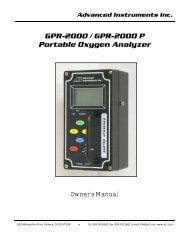
2 Quality Control CertificationAdvanced Instruments Inc.Date: Customer: Order No.: PassModel: ( ) <strong>GPR</strong>-<strong>18</strong><strong>MS</strong> <strong>Explosion</strong> <strong>Proof</strong> ppm O2 <strong>Analyzer</strong> S/N ______________________( ) <strong>GPR</strong>-<strong>18</strong> <strong>Explosion</strong> <strong>Proof</strong> ppm O2 <strong>Analyzer</strong> S/N ______________________( ) <strong>GPR</strong>-28 <strong>Explosion</strong> <strong>Proof</strong> O2 <strong>Analyzer</strong> S/N ______________________Sensor: ( ) <strong>GPR</strong>-12-2000<strong>MS</strong> ppm <strong>Oxygen</strong> Sensor S/N ______________________( ) <strong>GPR</strong> or ( ) XLT-12-333 ppm <strong>Oxygen</strong> Sensor S/N ______________________( ) <strong>GPR</strong>-11-32 or ( ) XLT-11-24 <strong>Oxygen</strong> Sensor S/N ______________________Approvals:Accessories:Configuration:<strong>ATEX</strong> certified Ex d IIB T6 or Ex d IIB+H2; certificate #INERIS07<strong>ATEX</strong>0025XEN 61326 Minimum Immunity TestEN 61010-1:2001 Low Voltage Directive (see Appendix A, B, C, D)Owner’s Manual5/16 Open end wrenchA-1107-M PCB Assembly Main / DisplayA-1106-M PCB Assembly Power / RelayRange: ( ) <strong>GPR</strong>-<strong>18</strong><strong>MS</strong> 0-1 ppm, 0-10 ppm, 0-100 ppm, 0-1000 ppm( ) <strong>GPR</strong>-<strong>18</strong> 0-10 ppm, 0-100 ppm, 0-1000 ppm, 0-25% (air calibration only)( ) <strong>GPR</strong>-28 0-1%, 0-5%, 0-10%, 0-25%Wetted parts: stainless steel ( ) Manual flow and bypass valves, flow indicator( ) Manual flow meter (with integral metering valve)Standard power: ( ) 100/110 VAC or ( ) 220/240 VACHeater system:( ) 100/110 VAC or ( ) 220/240 VAC; controller set at 85° FTest – Electronics:Test – Gas:Final:LED indicators: range, alarms4-20mA offsetAlarm relays activate/deactivate with changes in O 2 concentrationAnalog signal output 0-1V and 4-20mARange ID contacts (optional)Baseline drift on zero gas < ± 2% F.S. over 24 hour periodNoise level < ± 1.0% F.S.Span adjustment within 10-50% F.S.Peak to peak over / under shoot < 0.5% F.S.Overall inspection for physical defects; place SAMPLE/BYPASS valve in BYPASS positionOptions:Notes:4