GPR-2600 Series Oxygen Analyzer - Advanced Instruments Inc.
GPR-2600 Series Oxygen Analyzer - Advanced Instruments Inc.
GPR-2600 Series Oxygen Analyzer - Advanced Instruments Inc.

Create successful ePaper yourself
Turn your PDF publications into a flip-book with our unique Google optimized e-Paper software.
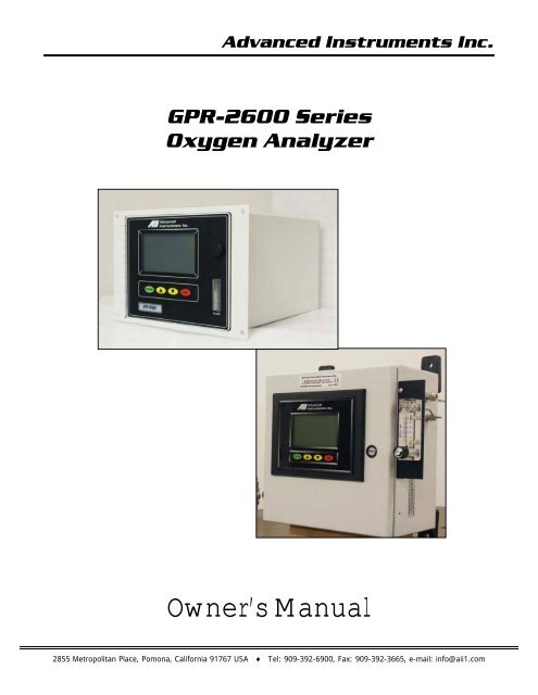
<strong>Advanced</strong> <strong>Instruments</strong> <strong>Inc</strong>.<strong>GPR</strong>-<strong>2600</strong> <strong>Series</strong><strong>Oxygen</strong> <strong>Analyzer</strong>Owner’s Manual2855 Metropolitan Place, Pomona, California 91767 USA ♦ Tel: 909-392-6900, Fax: 909-392-3665, e-mail: info@aii1.com
<strong>Advanced</strong> <strong>Instruments</strong> <strong>Inc</strong>.Table of ContentsIntroduction 1Quality Control Certification 2Safety & Installation 3Features & Specifications 4Operation 5Maintenance 6Spare Parts 7Troubleshooting 8Warranty 9Material Safety Data Sheets 101 IntroductionYour new oxygen analyzer is a precision piece of equipment designed to give you years of use in variety of industrial oxygenapplications.This analyzer is designed to measure the oxygen concentration in inert gases, gaseous hydrocarbons, hydrogen, and a varietyof gas mixtures. In order to derive maximum performance from your new oxygen analyzer, please read and follow theguidelines provided in this Owner’s Manual.The serial number of this analyzer may be found on the inside the analyzer. You should note the serial number in the spaceprovided and retains this Owner’s Manual as a permanent record of your purchase, for future reference and for warrantyconsiderations.Serial Number: _______________________Every effort has been made to select the most reliable state of the art materials and components designed for superiorperformance and minimal cost of ownership. This analyzer was tested thoroughly by the manufacturer for best performance.However, modern electronic devices do require service from time to time. The warranty included herein plus a staff of trainedprofessional technicians to quickly service your analyzer is your assurance that we stand behind every analyzer sold.<strong>Advanced</strong> <strong>Instruments</strong> <strong>Inc</strong>. appreciates your business and pledge to make effort to maintain the highest possible qualitystandards with respect to product design, manufacturing and service.2
<strong>Advanced</strong> <strong>Instruments</strong> <strong>Inc</strong>.2 Quality Control CertificationDate: Customer: Order No.: PassModel: <strong>GPR</strong>-<strong>2600</strong> ppm <strong>Oxygen</strong> <strong>Analyzer</strong> S/N _____________________Sensor:Accessories:Configuration:( ) <strong>GPR</strong>-12-333 ppm <strong>Oxygen</strong> Sensor( ) XLT-12-333 ppm <strong>Oxygen</strong> Sensor S/N _____________________Owner’s ManualCABL-1008 Power CordTOOL-1001 5/16” Combination WrenchRanges: 0-1 ppm, 0-10 ppm, 0-100 ppm, 0-1000 ppmA-1146-40 PCB Assembly Main / DisplaySoftware V. ______( ) A-1174-40 PCB Assy Power Supply / Interconnect, 4-20mA Range ID( ) A-1174-40C PCB Assy Power Supply / Interconnect, 5x Relay Contacts Range ID( ) Stainless steel sensor housing, manual flow control and bypass valves, ¼” compressiontype fittings for sample inlet and vent( ) Delete bypass valve from above (T and TO options)( ) Sample, span, zero inlet solenoid valves( ) Temperature controlled heater system 85°F specify: ( ) 110VAC ( ) 220VACPower: 100/120/220/250 VAC (universal without temperature controlled heater systems)Enclosure: ( ) Std. panel mount (“T”) 7.5x10.8x12”; ( ) “TO” option 7.75x 7.75x12”( ) Bezel for 19” rack mmount 19x12x12” option( ) <strong>GPR</strong>-<strong>2600</strong>-W option general purpose wall mount 12x12x8”TestOptionsNotesSystem start-up diagnostics satisfactoryAuto/manual rangeAlarm relays activate/deactivate with changes in O 2 concentrationAlarm bypassAnalog outputs: Signal output 4-20mARange ID: ( ) 4-20mA or ( ) 5x relay contacts plus 1x commonRecovery from air to < 10 ppm in < 15 minutesBaseline drift on zero gas < ± 2% FS over 24 hour periodNoise level < ± 1.0% FSSpan calibration gas valueSpan adjustment within 10-50% FSPeak to peak over/under shoot < 0.5% FSOverall inspection for physical defectsLabel analyzer “<strong>Oxygen</strong> Service” in accordance with P-1507 Rev-1; see certificate next page.3
<strong>Advanced</strong> <strong>Instruments</strong> <strong>Inc</strong>.Certificate of Cleaning<strong>Oxygen</strong> ServiceStandard:Mfg. Item No.:Description:Serial No.:Customer:Purchase Order:Quantity:Warranty Date:Manufacturing Procedure No. P-1057 Rev-1,Compressed Gas Association,Publication: G-4.1 Edition 4,Title: Cleaning Equipment for <strong>Oxygen</strong> Service,Published 1/1/1996 and related publications<strong>GPR</strong>-<strong>2600</strong> <strong>Series</strong><strong>Oxygen</strong> <strong>Analyzer</strong>_________________________________________________________________________________1 of12 months from ______________The undersigned warrants on behalf of Manufacturer that the product identified aboveconforms to the manufacturing, testing and packaging criteria set forth by the ‘Standard’specified above.Date:Place:______________Pomona, CABy print name:Signature:Title:4
<strong>Advanced</strong> <strong>Instruments</strong> <strong>Inc</strong>.3 Safety GuidelinesSafetyThis section summarizes the basic precautions applicable to all analyzers. Additional precautions specific to individual analyzerare contained in the following sections of this manual. To operate the analyzer safely and obtain maximum performance followthe basic guidelines outlined in this Owner’s Manual.Caution: This symbol is used throughout the Owner’s Manual to Caution and alert the user to recommended safety and/oroperating guidelines.Danger: This symbol is used throughout the Owner’s Manual to identify sources of immediate Danger such as the presence ofhazardous voltages.Read Instructions: Before operating the analyzer read the instructions.Retain Instructions: The safety precautions and operating instructions found in the Owner’s Manual should be retained forfuture reference.Heed Warnings Follow Instructions: Follow all warnings on the analyzer, accessories (if any) and in this Owner’s Manual.Observe all precautions and operating instructions. Failure to do so may result in personal injury or damage to the analyzer.Heat: Situate and store the analyzer away from sources of heat.Liquid and Object Entry: The analyzer should not be immersed in any liquid. Care should be taken so that liquids are notspilled into and objects do not fall into the inside of the analyzer.Handling: Do not use force when using the switches and knobs. Before moving your analyzer be sure to disconnect thewiring/power cord and any cables connected to the output terminals located on the analyzer.MaintenanceServiceability: Except for replacing the oxygen sensor, there are no parts inside the analyzer for the operator to service.Only trained personnel with the authorization of their supervisor should conduct maintenance.<strong>Oxygen</strong> Sensor: DO NOT open the sensor. The sensor contains a corrosive liquid electrolyte that could be harmful if touchedor ingested, refer to the Material Safety Data Sheet contained in this Owner’s Manual. Avoid contact with any liquid or crystaltype powder in or around the sensor or sensor housing, as either could be a form of electrolyte. Leaking sensors should bedisposed of in accordance with local regulations.Troubleshooting: Consult the guidelines in section 8 for advice on the common operating errors before concluding that youranalyzer is faulty. Do not attempt to service the analyzer beyond those means described in this Owner’s Manual.Do not attempt to make repairs by yourself as this will void the warranty, as detailed by section 9, and may result in electricalshock, injury or damage. All other servicing should be referred to qualified service personnel.Cleaning: The analyzer should be cleaned only as recommended by the manufacturer. Wipe off dust and dirt from the outsideof the unit with a soft damp cloth then dry immediately. Do not use solvents or chemicals.Nonuse Periods: Disconnect the power when the analyzer is left unused for a long period of time.5
<strong>Advanced</strong> <strong>Instruments</strong> <strong>Inc</strong>.InstallationGas Sample Stream: Ensure the gas stream composition of the application is consistent with the specifications and review theapplication conditions before initiating the installation. Consult the factory to ensure the sample is suitable for analysis.Contaminant Gases: A gas scrubber and flow indicator with integral metering valve are required upstream of the of theanalyzer to remove interfering gases such as oxides of sulfur and nitrogen or hydrogen sulfide that can produce false readings,reduce the expected life of the sensor and void the sensor warranty if not identified at time of order placement. Installation of asuitable scrubber is required to remove the contaminant from the sample gas to prevent erroneous analysis readings anddamage to the sensor or optional components. Consult the factory for recommendations concerning the proper selection andinstallation of components.Expected Sensor Life: With reference to the publish specification located as the last page of this manual, the expected life ofall oxygen sensors is predicated on oxygen concentration (< 1000 ppm or air), temperature (77°F/25°C) and pressure (1atmosphere) in “normal” applications. As a rule of thumb sensor life is inversely proportional to changes in the parameters.Deviations are outside the specifications and will affect the life of the sensor. Avoid exposure to oxygen levels near 100% for anextended period of time.Accuracy & Calibration: Refer to section 5 Operation. The 0-25% range is provided not only as a measuring range but forthe purpose of air calibration which is the recommended method of calibration. Optionally, the analyzer can be calibrated with acertified span gas or compressed instrument air at the user’s discretion. Note: The oxygen sensor’s inherent linearity andabsolute zero properties facilitates single point calibration.Materials: Assemble the necessary zero, purge and span gases and optional components such as valves, coalescing orparticulate filters, and, pumps as dictated by the application; stainless steel tubing is essential for maintaining the integrity ofthe gas stream for ppm and percentage range (above or below ambient air) analysis; hardware for mounting.Operating Temperature: The sample must be sufficiently cooled before it enters the analyzer and any optional components.A coiled 10 foot length of ¼” stainless steel tubing is sufficient for cooling sample gases as high as 1,800ºF to ambient. Themaximum operating temperature is 45º C on an intermittent basis unless the user is willing to accept a reduction in expectedsensor life – refer to analyzer specification - where expected sensor life is specified at an oxygen concentration less than 1000ppm oxygen for ppm analyzers and air (20.9% oxygen) for percent analyzers, but in all instances at 25°C and 1 atmosphere ofpressure. Expected sensor varies inversely with changes in these parameters.Pressure & FlowAll electrochemical oxygen sensors respond to partial pressure changes in oxygen. The sensors are equally capable of analyzingthe oxygen content of a flowing sample gas stream or monitoring the oxygen concentration in ambient air (such as a confinedspace such in a control room or an open area such as a landfill or bio-pond).<strong>Analyzer</strong>s designed for in-situ ambient or area monitoring have no real inlet and vent pressure because the sensor is exposeddirectly to the sample gas and intended to operate at atmospheric pressure, however, slightly positive pressure has minimaleffect on accuracy.Sample systems and flowing gas samples are generally required for applications involving oxygen measurements at oxygenconcentrations and pressures other than ambient air. In these situations, the use of stainless steel tubing and fittings is criticalto maintaining the integrity of the gas stream to be sampled and the inlet pressure must always be higher than the pressure atthe outlet vent which is normally at atmospheric pressure.The sensor is exposed to sample gas that must flow or be drawn through metal tubing inside the analyzer. The internal samplesystem includes 1/8” compression inlet and vent fittings, a corrosion resistant or stainless steel sensor housing with an o-ringseal to prevent the leakage of air and stainless steel tubing.Inlet Pressure: <strong>Analyzer</strong>s designed for flowing samples under positive pressure or pump vacuum (for samples at atmosphericor slightly negative atmospheres) that does not exceed 14” water column are equipped with bulkhead tube fitting connectionson the side of the unit (unless otherwise indicated, either fitting can serve as inlet or vent) and are intended to operate atpositive pressure regulated to between 5-30 psig although the rating of the fitting itself is considerably higher. Caution: If theanalyzer is equipped with an optional H2S scrubber, inlet pressure must not exceed 30 psig.6
<strong>Advanced</strong> <strong>Instruments</strong> <strong>Inc</strong>.Outlet Pressure: In positive pressure applications the vent pressure must be less than the inlet, preferably atmospheric.Flow Rate: Flow rates of 1-5 SCFH cause no appreciable change in the oxygen reading. However, flow rates above 5 SCFHgenerate backpressure and erroneous oxygen readings because the diameter of the integral tubing cannot evacuate the samplegas at the higher flow rate. The direction the sample gas flows is not important, thus either tube fitting can serve as the inlet orvent – just not simultaneously.A flow valve upstream (with flow indicator positioned downstream) of the sensor is recommended as a means of controlling theflow rate of the sample gas, minimizing air leaks and produce optimum accuracy. A flow rate of 2 SCFH or 1 liter per minute isrecommended for optimum performance.Caution: Do not place your finger over the vent (it pressurizes the sensor) to test the flow indicator when gas is flowing to thesensor. Removing your finger (the restriction) generates a vacuum on the sensor and may damage the sensor (voiding thesensor warranty). To avoid generating a vacuum on the sensor (as described above) during operation, always select and installthe vent fitting first and remove the vent fitting last.Application Pressure - Positive: A flow indicator with integral metering valve positioned upstream of the sensor isrecommended for controlling the sample flow rate between 1-5 SCFH. To reduce the possibility of leakage for low ppmmeasurements, position a metering needle valve upstream of the sensor to control the flow rate and position a flow indicatordownstream of the sensor. If necessary, a pressure regulator (with a metallic diaphragm is recommended for optimumaccuracy, the use of diaphragms of more permeable materials may result in erroneous readings) upstream of the flow controlvalve should be used to regulate the inlet pressure between 5-30 psig.Caution: If the analyzer is equipped with a H2S scrubber as part of an optional sample conditioning system, inlet pressuremust not exceed 30 psig.Application Pressure - Atmospheric or Slightly Negative: For accurate ppm range oxygen measurements, an optionalexternal sampling pump should be positioned downstream of the sensor to draw the sample from the process, by the sensorand out to atmosphere. A flow meter is generally not necessary to obtain the recommended flow rate with most samplingpumps.Caution: If the analyzer is equipped with an optional flow indicator with integral metering valve or a metering flow controlvalve upstream of the sensor - open the metering valve completely to avoid drawing a vacuum on the sensor and placing anundue burden on the pump. If pump loading is a consideration, a second throttle valve on the pump’s inlet side may benecessary to provide a bypass path so the sample flow rate is within the above parameters.Recommendations to avoid erroneous oxygen readings and damaging the sensor:‣ Do not place your finger over the vent (it pressurizes the sensor) to test the flow indicator when gas is flowing to thesensor. Removing your finger (the restriction) generates a vacuum on the sensor and may damage the sensor (thus voidingthe sensor warranty).‣ Assure there are no restrictions in the sample or vent lines‣ Avoid drawing a vacuum that exceeds 14” of water column pressure – unless done gradually‣ Avoid excessive flow rates above 5 SCFH which generate backpressure on the sensor.‣ Avoid sudden releases of backpressure that can severely damage the sensor.‣ Avoid the collection of liquids or particulates on the sensor, they block the diffusion of oxygen into the sensor - wipe away.‣ If the analyzer is equipped with an optional integral sampling pump (positioned downstream of the sensor) and a flowcontrol metering valve (positioned upstream of the sensor), completely open the flow control metering valve to avoiddrawing a vacuum on the sensor and placing an undue burden on the pump.Moisture & Particulates: Installation of a suitable coalescing or particulate filter is required to remove condensation, moistureand/or particulates from the sample gas to prevent erroneous analysis readings and damage to the sensor or optionalcomponents. Moisture and/or particulates do not necessarily damage the sensor, however, collection on the sensing surface canblock or inhibit the diffusion of sample gas into the sensor resulting in a reduction of sensor signal output – and the appearanceof a sensor failure when in fact the problem is easily remedied by blowing on the front of the sensor. Consult the factory forrecommendations concerning the proper selection and installation of components.Moisture and/or particulates generally can be removed from the sensor by opening the sensor housing and either blowing onthe sensing surface or gently wiping or brushing the sensing surface with damp cloth.7
<strong>Advanced</strong> <strong>Instruments</strong> <strong>Inc</strong>.Mounting: The analyzer is approved for indoor use, outdoor use requires optional enclosures, consult factory. Mount asrecommended by the manufacturer.Gas Connections: Inlet and outlet vent gas lines for ppm analysis require 1/8” or ¼” stainless steel compression fittings; hardplastic tubing with a low permeability factor can be used percentage range measurements.Power: Supply power to the analyzer only as rated by the specification or markings on the analyzer enclosure. The wiring thatconnects the analyzer to the power source should be installed in accordance with recognized electrical standards. Ensure that isproperly grounded and meets the requirements for area classification. Never yank wiring to remove it from a terminalconnection. AC powered analog analyzers consume 5 watts, digital analyzers 50 watts without optional heaters. Optional 110Vand 220V heaters AC powered heaters consume an additional 100-150 watts; DC powered digital analyzers consume 30 watts,40 watts with the optional DC powered heater.8
<strong>Advanced</strong> <strong>Instruments</strong> <strong>Inc</strong>.4 Features & Specifications9
<strong>Advanced</strong> <strong>Instruments</strong> <strong>Inc</strong>.10
<strong>Advanced</strong> <strong>Instruments</strong> <strong>Inc</strong>.5 OperationPrinciple of OperationThe <strong>GPR</strong>-<strong>2600</strong> ppm <strong>Oxygen</strong> <strong>Analyzer</strong>s incorporates a a variety of ppm range advanced galvanic fuel cell type sensors and isconfigured for panel mounting and requires a 7.5x10.8” (T configuration) cutout with 4 holes for the analyzer’s front panel.Optional configurations include a panel mount (TO configuration) 7.75x7.75” with cutout; 19” bezel for rack mounting either theT or TO; 12x12x8” wall mount enclosure (<strong>GPR</strong>-<strong>2600</strong>W). Contact the factory for additional information on options. Allconfigurations are tested and calibrated by the manufacturer prior to shipment. The <strong>GPR</strong>-<strong>2600</strong> analyzers and sensors are CEcertified and manufactured under a Quality Assurance System certified by an independent agency to ISO 9001:2000 standards.<strong>Advanced</strong> Galvanic Sensor TechnologyThe sensors function on the same principle and are specific for oxygen. They measure the partial pressure of oxygen from lowppm to 100% levels in inert gases, gaseous hydrocarbons, helium, hydrogen, mixed gases, acid gas streams and ambient air.<strong>Oxygen</strong>, the fuel for this electrochemical transducer, diffusing into the sensor reacts chemically at the sensing electrode toproduce an electrical current output proportional to the oxygen concentration in the gas phase. The sensor’s signal output islinear over all ranges and remains virtually constant over its useful life. The sensor requires no maintenance and is easily andsafely replaced at the end of its useful life.Proprietary advancements in design and chemistry add significant advantages to an extremely versatile oxygen sensingtechnology. Extending the expected life of our new generation of percentage range sensors now range to five and ten yearswith faster response times and greater stability. Another significant development involves the first galvanic oxygen sensorcapability of continuous oxygen purity measurements and expanding the operating temperature range from -40°C to 50°C,excellent compatibility with CO 2 and acid gases (XLT series) and reliable quality giving them a significant advantage over thecompetition.<strong>Oxygen</strong>, the fuel for this electrochemical transducer, reacts chemically at the sensing electrode to produce an electrical currentoutput proportional to the oxygen concentration in the gas phase. The sensor’s signal output is linear over all four ranges andremains virtually constant over its useful life. The sensor requires no maintenance or electrolyte addition and is easily and safelyreplaced at the end of its useful life.11
<strong>Advanced</strong> <strong>Instruments</strong> <strong>Inc</strong>.ElectronicsThe signal generated by the sensor is processed by state of the art low power micro-processor based digital circuitry. The firststage amplifies the signal. The second stage eliminates the low frequency noise. The third stage employs a high frequency filterand compensates for signal output variations caused by ambient temperature changes. The result is a very stable signal.Sample oxygen is analyzed very accurately. Response time of 90% of full scale is less than 10 seconds (actual experience mayvary due to the integrity of sample line connections, dead volume and flow rate selected) on all ranges under ambientmonitoring conditions. Sensitivity is typically 0.5% of full scale low range.Additional features of the micro-processor based electronics include manual or auto ranging, auto-zero and auto-cal, isolated 4-20mA signal for signal output and range ID, separate relay contacts rated 30VDC max @ 1A are provided for the alarm featureand an optional range ID feature (auto-zero/auto-cal with relay contacts for Range ID is special order, so . Whenever theanalyzer is calibrated, a unique algorithm predicts and displays a message indicating a ‘weak sensor’ suggesting the sensor bereplaced in the near future.Sample SystemThe sample must be properly presented to the sensor to ensure an accurate measurement. In standard form the <strong>GPR</strong>-<strong>2600</strong> isdesigned with a sample system that enables the user to control the flow rate via a flow meter positioned upstream of thesensor. The sensor is exposed to sample gas that must flow or be drawn through the analyzer’s internal sample system.<strong>Advanced</strong> <strong>Instruments</strong> <strong>Inc</strong>. offers a full line of sample handling, conditioning and expertise to meet your applicationrequirements. Contact us at 909-392-6900 or e-mail us at info@aii1.com12
<strong>Advanced</strong> <strong>Instruments</strong> <strong>Inc</strong>.Accuracy OverviewSingle Point Calibration: As previously describedthe galvanic oxygen sensor generates an electricalcurrent proportional to the oxygen concentration inthe sample gas. In the absence of oxygen the sensorexhibits an absolute zero, e.g. the sensor does notgenerate a current output in the absence of oxygen.Given these linearity and absolute zero properties,single point calibration is possible.Pressure: Because sensors are sensitive to thepartial pressure of oxygen in the sample gas theiroutput is a function of the number of molecules ofoxygen 'per unit volume'. Readouts in percent arepermissible only when the total pressure of thesample gas being analyzed remains constant. Thepressure of the sample gas and that of the calibrationgas(es) must be the same (reality < 1-2 psi).Temperature: The rate oxygen molecules diffuse into the sensor is controlled by a Teflon membrane otherwise known as an'oxygen diffusion limiting barrier' and all diffusion processes are temperature sensitive, the fact the sensor's electrical outputwill vary with temperature is normal. This variation is relatively constant 2.5% per ºC. A temperature compensation circuitemploying a thermistor offsets this effect with an accuracy of +5% or better and generates an output function that isindependent of temperature. There is no error if the calibration and sampling are performed at the same temperature or if themeasurement is made immediately after calibration. Lastly, small temperature variations of 10-15º produce < 1% error.Accuracy: In light of the above parameters, the overall accuracy of an analyzer is affected by two types of errors:1) those producing 'percent of reading errors', illustrated by Graph A below, such as +5% temperature compensation circuit,tolerances of range resistors and the 'play' in the potentiometer used to make span adjustments and2) those producing 'percent of full scale errors', illustrated by Graph B, such as +1-2% linearity errors in readout devices, whichare really minimal due to today's technology and the fact that other errors are 'spanned out' during calibration.Graph C illustrates these 'worse case' specifications that are typically used to develop an analyzer's overall accuracy statementof < 1% of full scale at constant temperature or < 5% over the operating temperature range. QC testing is typically < 0.5%prior to shipment.Example 1: As illustrated by Graph A any error, play in the multi-turn span pot or the temperature compensation circuit,during a span adjustment at 20.9% (air) of full scale range would be multiplied by a factor of 4.78 (100/20.9) if used formeasurements of 95-100% oxygen concentrations. Conversely, an error during a span adjustment at 100% of full scale range isreduced proportionately for measurements of lower oxygen concentrations.Refer to the Calibration section for additional details.13
<strong>Advanced</strong> <strong>Instruments</strong> <strong>Inc</strong>.Mounting the <strong>Analyzer</strong>The standard <strong>GPR</strong>-<strong>2600</strong> is designed to be panel mounted and requires a cutout that accommodates the enclosure and 4mounting bolts. The design also lends itself to 19” rack mounting with an optional bezel or wall mount enclosures as illustratedbelow.Procedure:1. The <strong>GPR</strong>-<strong>2600</strong> is designed for panel mounting directly to any flat vertical surface, wall or bulkhead plate with theappropriate cut out and four ¼” diameter holes for insertion of the mounting studs located on the back side of the frontpanel.2. When mounting the analyzer position it approximately 5 feet off the floor for viewing purposes and allow sufficient room foraccess to the terminal connections at the rear of the enclosure.3. Note: The proximity of the analyzer to the sample point and use of optional sample conditioning components have animpact on sample lag time.Mounting <strong>GPR</strong>-<strong>2600</strong>:14
<strong>Advanced</strong> <strong>Instruments</strong> <strong>Inc</strong>.Mounting <strong>GPR</strong>-<strong>2600</strong>-W Option:15
<strong>Advanced</strong> <strong>Instruments</strong> <strong>Inc</strong>.Gas ConnectionsThe <strong>GPR</strong>-<strong>2600</strong> with its standard flow through configuration is designed for positive pressure samplesand requires connections for incoming sample and outgoing vent lines, see illustrations above.The user is responsible for calibration gases and the components described below. Flow rates of 1-5SCFH cause no appreciable change in the oxygen reading. A flow valve upstream (flow indicatordownstream) of the sensor is recommended as a means of controlling the flow rate of the samplegas. A flow rate of 2 SCFH is recommended for optimum performance.Caution: Do not place your finger over the fitting designated as the vent (it pressurizes the sensor)or to test the flow indicator when gas is flowing to the sensor. Removing your finger (the restriction)generates a vacuum on the sensor and may damage the sensor (voiding the sensor warranty).Procedure:1. Caution: Do not change the factory setting until instructed.2. Regulate the pressure and flow as described in Pressure & Flow above.3. Install the sample out or vent line connection to the 1/8” dia. fitting labeled SAMPLE VENT.4. Install the incoming sample or span gas line to the 1/8” dia. fitting labeled SAMPLE IN.5. Set the flow rate to 1 SCFH (open the flow control valve completely if using an external sampling pump positioneddownstream of the sensor).6. Allow gas to flow through the analyzer for 3-5 minutes and proceed to Calibration or Sampling.16
<strong>Advanced</strong> <strong>Instruments</strong> <strong>Inc</strong>.Electrical Connections:<strong>Inc</strong>oming power for the 100-250V AC powered analyzers is supplied through a universal power entry module. A standardcomputer type power cord (P/N A-1008) is required for the universal power entry module. A well grounded insulated powercable is recommended to avoid noise resulting from unwanted interference.The appropriate AC power supply (110V or 220V) must specified be specified at order placement if the analyzer is to beequipped with proper the temperature control heater system.Power consumption is approximately 150-200 watts with the temperature control heater system and 30 watts without.Caution: Integral 4-20mA converters are internally powered and do not require external power. DO NOT supply any voltage toany of the terminals for 4-20mA signal output and range ID or the 4-20mA converters will be damaged.Caution: To assure proper grounding, connect the 4-20mA signal output to the external device (PLC, DCS, etc.) beforeattempting any zero or span adjustments.Optional Range ID:The standard 4-20mA output used for range identification, as described below, can be replaced by eliminating the alarmsfeature and using the relay contacts associated with the alarms to provide a single common and four (4) normally open relaycontacts that close when the related range is active. The dry contacts are rated at 30VDC @ 1A and powering them is notrequired if the PLC can distinguish contact closure via continuity check.17
<strong>Advanced</strong> <strong>Instruments</strong> <strong>Inc</strong>.Procedure:1. As illustrated above the sensor, power and alarm relays and signal output connections are hard wired to screw typeterminal blocks located at the rear of the analyzer.2. Use a small bladed screwdriver to loosen the appropriate terminal screws as illustrated above.3. Strip the wires of the cable no more than 3/16 inch.4. To connect to an active relay or “fail safe”, connect the live cable to the common terminal C and the secondary cable to thenormally open NO terminal.5. To break the connection upon relay activation, connect the secondary cable to the normally closed NC terminal.6. Insert the stripped end of the cables into the appropriate terminal slots assuring no bare wire remains exposed that couldcome in contact with the back panel of the analyzer enclosure.7. Tighten the terminal screws to secure the wires of the cable.Danger: While connecting the cables to the relay terminals, ensure there is no voltage on the cables to prevent electric shockand possible damage to the analyzer. Caution: Assure the stripped wire ends of the cable are fully inserted into the terminalslots and do not touch each other or the back panel of the analyzer enclosure.Interconnections for the optional wall mount enclosure pictured below.18
<strong>Advanced</strong> <strong>Instruments</strong> <strong>Inc</strong>.AlarmsThe analyzer is configured with two user adjustable threshold type alarm relays that can be configured in the field from theALARM option on the MAIN MENU as follows:‣ Establish independent set points‣ Either Hi or Lo‣ Either On or Off (enabled or disabled)‣ Both temporarily defeated using a user entered ‘timeout’ period (normally minutes)The alarm set point represents a value. When the oxygen reading exceeds (high alarm) or falls below (low alarm) the alarm setpoint, the relay is activated and the LCD displays the alarm condition.When activated the alarms trigger SPDT Form C non-latching relays @ 5A, 30VDC or 240VAC resistive. To prevent chattering ofthe relays, a 2% hysteresis is added to the alarm set point. This means that the alarm will remain active until the oxygenreading has fallen 2% below the alarm set point (high alarm) or risen 2% above the alarm set point (low alarm) after the alarmwas activated. The timeout feature is useful while replacing the oxygen sensor or during calibration when the oxygen readingmight well rise above the alarm set point and trigger a false alarm.Note: When making connections the user must decide whether to configure/connect Alarm 1 and Alarm 2 in failsafe mode(Normally Open – NO – where the alarm relay de-energizes and closes in an alarm condition) or non-failsafe mode (NormallyClosed – NC – where alarm relay energizes and opens in an alarm condition).Power Failure AlarmA dry contact rated at 30VDC @ 1A is provided as a power failure alarm that activates when power supplied to the analyzer’scircuits is unacceptable. The contact is normally closed but opens when the power to the analyzer is switched off or interruptedand cannot be disabled.4-20mA Signal OutputThe analyzer provides a 4-20mA full scale fully isolated ground signals for external recording devices. The integral IC on themain PCB provides 4-20mA fully isolated signals for output and range ID. The 4-20mA current output is obtained by connectingthe current measuring device between the positive and negative terminals labeled OUTPUT 4-20mA. To check the signal outputof the 4-20mA E/I integrated circuit connect an ammeter as the measuring device and confirm the output is within +0.1mA of4mA. A finer adjustment of the zero offset of the 4-20mA converter can be provided by a potentiometer mounted on the mainPCB Assembly. Consult factory for instructionsRange IDFor range ID the output of 4mA, 8mA, 12mA, 16mA, 20mA correspond to the most sensitive to least sensitive analysis range.The standard 4-20mA output used for range indentification, as described below, can be replaced by eliminating the alarmsfeature and using the relay contacts associated with the alarms to provide a single common and four (4) normally open relaycontacts that close when the related range is active. The dry contacts are rated at 30VDC @ 1A and powering them is optionalas some PLCs can distinguish contact closure via continuity check.Caution: The integral 4-20mA converters are internally powered and do not require external power. DO NOT supply anyvoltage to any of the two terminals of the 4-20mA converter.19
<strong>Advanced</strong> <strong>Instruments</strong> <strong>Inc</strong>.Optional - Temperature Controlled Heater System with Runaway Protection CircuitThe standard <strong>GPR</strong>-<strong>2600</strong> <strong>Series</strong> analyzer is not equipped with the heater system. However, in anticipation of very low ppm (highppb) oxygen analysis, the user may elect to add the heater system. If the analyzer is equipped with an optional temperaturecontrolled heater system, open the front door of the analyzer to access it. This unit is a PID controller which operates between0-99°F. The controller is programmed to maintain the temperature at 85°F.Caution: Do not change this setting. A higher temperaturesetting may drastically reduce sensor life and possibly causedamage to the electronic circuitry of both the controller and theanalyzer.Warning: Keep the front door securely fastened and closed whenthe temperature controller is ON.When power is applied to the temperature controller, the controllertunes itself to eliminate and/or minimize the over/under shoot oftemperature from the set point. It is recommended that at initialstart-up, when replacing the oxygen sensor or when troubleshooting, turn off the power to the heater or set the temperatureset point at 60°F (to turn the heater off) to prevent overheatingthe analyzer. When operating the analyzer under normalconditions, set the temperature controller at 85⁰F.Pictured with optional stainless steel sensor housingChanging the display value from °F to °C:1. Push the UP ARROW and ENTER buttons down for 5 seconds to access the SECURE MENU2. Press INDEX to advance to the F-C MENU3. Select °C or °F by pressing the UP ARROW key4. Press the ENTER key when F-C starts flashing on the display5. Press INDEX to exit the SECURE MENUHeater Runaway ProtectionPart of the optional temperature controlled heater system is a heater runaway protection circuit that protects the electronics inthe event the temperature controller should fail and thereby allowing the heater to runaway damaging the components insidethe analyzer.The runaway protection is provided by a J2 type device positioned between the temperature controller and the heater. Thisdevice cuts-off power to the heater if the temperature inside the analyzer exceeds 70°C. Should the J2 device cut power to theheater, correct the problem and reset the runaway protector device by exposing it to 0°C for a few minutes (a refrigeratorfreezer will do).20
<strong>Advanced</strong> <strong>Instruments</strong> <strong>Inc</strong>.Span Gas PreparationThe analyzer must be calibrated periodically. See the Calibration section below for recommendations. Caution: Do notcontaminate the span gas cylinder when connecting the regulator. Bleed the air filled regulator (faster and more reliable thansimply flowing the span gas) before attempting the initial calibration of the instrument.Required components:‣ Certified span gas cylinder with an oxygen concentration, balance nitrogen, approximating 80% of the full scale rangeabove the intended measuring range.‣ Regulator to reduce pressure to 30 psig.‣ Flow meter to set the flow between 1 SCFH,‣ Suitable fittings and 1/8” dia. 4-6 ft. in length of metal tubing to connect the regulator to the flow meter inlet‣ Suitable fitting and 1/8” dia. 4-6 ft. in length of metal tubing to connect from the flow meter vent to tube fitting designatedSAMPLE IN on the <strong>GPR</strong>-<strong>2600</strong>.Procedure:1. With the span gas cylinder valve closed, install the regulator on the cylinder.2. Open the regulator’s exit valve and partially open the pressure regulator’s control knob.3. Open slightly the cylinder valve.4. Loosen the nut connecting the regulator to the cylinder and bleed the pressure regulator.5. Retighten the nut connecting the regulator to the cylinder6. Adjust the regulator exit valve and slowly bleed the pressure regulator.7. Open the cylinder valve completely.8. Set the pressure between 5-30 psig using the pressure regulator’s control knob.9. Caution: Do not exceed the recommended flow rate. Excessive flow rate could cause the backpressure on the sensorand may result in erroneous readings and permanent damage to the sensor.Establishing Power to the Electronics:Once the power to the electronics is established, the digital display responds instantaneously. When power is applied, theanalyzer performs several diagnostic system status checks termed “SYSTEM SELF TEST” as illustrated below:System Self TestCPUMemoryRTCAnalogOKOKOKOK<strong>GPR</strong> <strong>Series</strong> <strong>Oxygen</strong> <strong>Analyzer</strong>Software Version X.XX<strong>Advanced</strong> <strong>Instruments</strong>2855 Metropolitan PlacePomona, CA 91767Tel: 909-392-6900Fax: 909-392-3665e-mail: info@aii1.com21
<strong>Advanced</strong> <strong>Instruments</strong> <strong>Inc</strong>.After 3 seconds the system defaults to the STANDBY mode and the LCD displays the following:* MAIN MENUSampleSpanZeroAlarmSystemStandbyStandbyAuto Range85⁰F 100Kpa 12/31/07 12:00:00Menu FormatMenu displayed – displayed on the top line in the upper left corner of the display.Menu options available - displayed in the upper left corner of the display under the current menu on the top line.Menu option selected - indicated by the cursor (*) positioned to the left of the menu option selected.System mode - indicated at the top center of the display.Range mode and current auto or fixed manual range - displayed on the first line at the bottom of the display.Temperature inside the analyzer and ambient pressure - displayed on the second line at the bottom of the display.Note:In the event power to the analyzer is interrupted, the system defaults to the “Standby” mode when power isrestored. To resume sampling, advance the cursor (*) to “Sample” mode, press ENTER to select and select therange mode as described below.Menu NavigationThe four (4) pushbuttons located on the front of the analyzer control the system’s micro-processor:1. Green - ENTER (select)2. Yellow UP ARROW – advance cursor up3. Yellow DOWN ARROW – advance cursor down4. Red – ESC (menu)Select menu option by advancing cursor (*) by repeatedly pressing the yellow UP/DOWN ARROW keys.Accept the menu option selected with cursor (*) by pressing the green ENTER key.Abort the menu option selected with cursor (*) and return to the previous menu by pressing the red ESC key.Note:If a selection is not made within 30 seconds, the system returns to the MAIN MENU.22
<strong>Advanced</strong> <strong>Instruments</strong> <strong>Inc</strong>.Auto Range SamplingThe display will shift to the next higher range when the oxygen reading exceeds 99.9% of the current range. The display willshift to the next lower range when the oxygen reading drops to 85% of the next lower range.For example, if the analyzer is reading 1 ppm on the 0-10 ppm range and an upset occurs, the display will shift to the 0-100ppm range when the oxygen reading exceeds 9.99 ppm. Conversely, once the upset condition is corrected, the display will shiftback to the 0-10 ppm range when the oxygen reading drops to 8.5 ppm.Procedure:From the SAMPLE menu, advance the cursor (*) to the “Auto Range” option and press ENTER:SAMPLE* Auto RangeManual RangeBypassStandbyStandbyAuto Range85⁰F 100Kpa 12/31/07 12:00:00Note:To provide for the possibility of an optional automated sample system, the system displays the message “OpeningSample Valves” at this time. This message does not apply to analyzers equipped with the standard manually operatedsample system.Similarly, the Bypass and Standby options do not apply to analyzers equipped with manual sample systems.Within seconds the system assesses the oxygen concentration, selects the appropriate range (as described above) and returnsto the MAIN MENU in the “Sample” mode. On the top line at the bottom of the menu, the Auto Range mode is indicated as isthe current full scale range.* MAIN MENUSampleSpanZeroAlarmSystemStandbySample5.00 %Auto Range85⁰F 100Kpa0 to 10 %12/31/07 12:00:0024
<strong>Advanced</strong> <strong>Instruments</strong> <strong>Inc</strong>.Manual Range SamplingThe display will not shift automatically. Instead, when the oxygen reading exceeds 125% of the upper limit of the current rangean OVER RANGE warning will be displayed. Once the OVER RANGE warning appears the user must advance the analyzer to thenext higher range.Procedure:From the SAMPLE menu, advance the cursor (*) to the “Manual Range” option and press ENTER:SAMPLEAuto Range* Manual RangeBypassStandbyStandbyAuto Range85⁰F 100Kpa 12/31/07 12:00:00The following display appears:MANUAL RANGE0 to 25%0 to 1%0 to 1000 PPM0 to 100 PPM* 0 to 10 PPMStandbyAuto Range85⁰F 100Kpa 12/31/07 12:00:00Advance the cursor (*) to the desired fixed manual range, e.g. 0 to 10 ppm and press ENTER.Within seconds the system assesses the oxygen concentration and returns to the MAIN MENU in the “Sample” mode. On the topline at the bottom of the menu, the Manual Range mode is indicated as is the fixed full scale range selected.* MAIN MENUSampleSpanZeroAlarmSystemStandbySample5.00 %Manual Range85⁰F 100Kpa0 to 10 %12/31/07 12:00:0025
<strong>Advanced</strong> <strong>Instruments</strong> <strong>Inc</strong>.If the oxygen reading exceeds 99.9% of the full scale fixed range manually selected, the system displays the following:* MAIN MENUSampleSpanZeroAlarmSystemStandbySample5.00 %OVER RANGEManual Range85⁰F 100Kpa0 to 10 %12/31/07 12:00:00AlarmsThe analyzer is configured with two user adjustable threshold type alarm relays that can be configured in the field from theALARM option on the MAIN MENU as follows:‣ Establish independent set points‣ Either Hi or Lo‣ Either On or Off (enabled or disabled)‣ Both temporarily defeated using a user entered ‘timeout’ period (normally minutes)The alarm set point represents a value. When the oxygen reading exceeds (high alarm) or falls below (low alarm) the alarm setpoint, the relay is activated and the LCD displays the alarm condition.When activated the alarms trigger SPDT Form C non-latching relays @ 5A, 30VDC or 240VAC resistive. To prevent chattering ofthe relays, a 2% hysteresis is added to the alarm set point. This means that the alarm will remain active until the oxygenreading has fallen 2% below the alarm set point (high alarm) or risen 2% above the alarm set point (low alarm) after the alarmwas activated. The timeout feature is useful while replacing the oxygen sensor or during calibration when the oxygen readingmight well rise above the alarm set point and trigger a false alarm.Note: When making connections the user must decide whether to configure/connect Alarm 1 and Alarm 2 in failsafe mode(Normally Open – NO – where the alarm relay de-energizes and closes in an alarm condition) or non-failsafe mode (NormallyClosed – NC – where alarm relay energizes and opens in an alarm condition).Procedure:Advance the cursor (*) to the “Alarm” option and press the green ENTER key to accept the selection.MAIN MENUSampleSpanZero* AlarmSystemStandbySample5.00 %Auto Range85⁰F 100Kpa0 to 10 %12/31/07 12:00:0026
<strong>Advanced</strong> <strong>Instruments</strong> <strong>Inc</strong>.The following menu appears:ALARM* Set Alarm 1Set Alarm 2Alarm 1 HIAlarm 2 HIAlarm 1 ONAlarm 2 ONAlarm TimeoutSampleAuto Range 0 to 10 %85⁰F 100Kpa 12/31/07 12:00:00Advance the cursor (*) to the “Set Alarm 1” option and press the green ENTER key to accept the selection.The following menu appears:20%Press UP or DOWNto change valueENTER to SaveESC to ReturnSampleAuto Range 0 to 10 %85⁰F 100Kpa 12/31/07 12:00:00Follow the prompt above and press the ENTER key to save the alarm value (% full scale) or ESC to return to the MAIN MENU.Within a few seconds after pressing the ENTER key, the system returns to the MAIN MENU.Repeat the above steps for “Set Alarm 2”.Configure Alarm 1 and Alarm 2 by advancing the cursor (*) to the desired feature as illustrated below.ALARMSet Alarm 1Set Alarm 2* Alarm 1 HI / LO* Alarm 2 HI / LO* Alarm 1 ON / OFF* Alarm 2 ON / OFFAlarm TimeoutSampleAuto Range 0 to 10 %85⁰F 100Kpa 12/31/07 12:00:00Press the ENTER key to toggle between the settings: HI and LO and/or ON and OFF.After toggling, the system returns to the MAIN MENU. To confirm selection, re-access the ALARM menu above.27
<strong>Advanced</strong> <strong>Instruments</strong> <strong>Inc</strong>.Advance the cursor (*) to the “Alarm” option and press the green ENTER key to accept the selection.MAIN MENUSampleSpanZero* AlarmSystemStandbySample5.00 %Auto Range85⁰F 100Kpa0 to 10 %12/31/07 12:00:00The following menu appears:ALARMSet Alarm 1Set Alarm 2Alarm 1 HIAlarm 2 HIAlarm 1 ONAlarm 2 ON* Alarm TimeoutSampleAuto Range 0 to 10 %85⁰F 100Kpa 12/31/07 12:00:00Advance the cursor (*) to the “Alarm Timeout” option and press the green ENTER key to accept the selection.The following menu appears:20 MinutesPress UP or DOWNto change valueENTER to SaveESC to ReturnSampleAuto Range 0 to 10 %85⁰F 100Kpa 12/31/07 12:00:00Follow the prompt above and press the ENTER key to save the alarm timeout value or ESC to return to the MAIN MENU.Within a few seconds after pressing the ENTER key, the system returns to the MAIN MENU.28
<strong>Advanced</strong> <strong>Instruments</strong> <strong>Inc</strong>.System MenuThe analyzer is equipped with a wide range of features that enables users to enhance performance and tailor their interfacewith the analyzer. The SYSTEM menu shown below lists the features available and is followed by a description of each function.Most of the functions are initiated by toggling between options using the ENTER key as previously described.Advance the cursor (*) to the “Alarm” option and press the green ENTER key to accept the selection.MAIN MENUSampleSpanZeroAlarm* SystemStandbySample5.00 %Auto Range85⁰F 100Kpa0 to 10 %12/31/07 12:00:00The following menu appears:* SYSTEMEnable Low Flow AlarmDisable Alarm During CalSignal AverageRangeLogging IntervalTemp CoefficientView Data GraphSet Clock (and Date)Logging ONShow TextDisplay Negative (Reading) ONAdvance the cursor (*) to the desired option and press follow the instructions below.Enable Low Flow AlarmDisable Alarm During CalSignal AverageRangeLogging IntervalTemp CoefficientIf the analyzer is equipped with a low flow alarm, press ENTER key to toggle betweenENABLE and DISABLE.Press ENTER key to toggle between ENABLE and DISABLE.Press ENTER key to select and choose Low, Medium (default) or High – functions allowsusers to select their preference regarding the trade-off of response time vs. noisefiltering.Same as Manual Range option found on SAMPLE menu.Press ENTER key and a display appears similar to Alarm Timeout above for the user toenter the interval in minutes for capturing data points for logging purposes.Not operable at this time.29
<strong>Advanced</strong> <strong>Instruments</strong> <strong>Inc</strong>.View Data GraphSet Clock (and Date)LoggingShow TextDisplay Negative (Reading)Provided “Logging” feature below is toggled ON, selecting this feature provides afullscreen display or graph of the data points.Selecting this option generates a display for selecting Time or Date with each followedby a detailed display for setting hour, minute, second or year, month, day.Press ENTER key to toggle between ON and OFF.Press ENTER key to toggle between MAIN MENU display options:1.) Menu text with large numbers (as illustrated herein)2.) Menu text with small numbers and a small graph of O2 reading.Press the ENTER key to toggle between ON and OFF.Installation & Start-up is now complete . . .30
<strong>Advanced</strong> <strong>Instruments</strong> <strong>Inc</strong>.CalibrationThe electrochemical oxygen sensors manufactured by Analytical Industries <strong>Inc</strong>. (dba <strong>Advanced</strong> <strong>Instruments</strong>) generate anelectrical current that is linear or proportional to the oxygen concentration in the sample gas. In the absence of oxygen thesensor exhibits an absolute zero, e.g. the sensor does not generate a current output in the absence of oxygen. Given theproperties of linearity and an absolute zero, single point calibration is possible.As described below, zero calibration is recommended only when the application (or user) demands optimum accuracy foranalysis below 5% of the most sensitive or lowest range available on the analyzer. Span calibration in one of the formsdescribed below is sufficient for all other measurements. When employed zero calibration should precede span calibration.Zero CalibrationDespite the absolute zero inherent in electrochemical oxygen sensors, the reality is that analyzers display an oxygen readingwhen sampling a zero gas due to:‣ Contamination or quality of the zero gas‣ Minor leakage in the sample line connections‣ Residual oxygen dissolved in the sensor’s electrolyte‣ Tolerances of the electronic componentsThe zero capability (low end sensitivity) of every analyzer is qualified prior to shipment. However, because the factory samplesystem conditions differ from that of the user, no ZERO OFFSET adjustment is made to the analyzer by the factorySpan CalibrationInvolves periodically, see Intervals section below, checking and/or adjusting the electronics to the sensor’s signal output at agiven oxygen standard or span. Maximum drift from calibration temperature is approximately 0.11% of reading per °C. Thefrequency of calibration varies with the application conditions (potential for contamination), the degree of accuracy required bythe application and the quality requirements of the user. However, the interval between span calibrations should not exceedthree (3) months.Note: Regardless of the oxygen concentration of the standard used, the span calibration process takes approximately 10minutes, however, the time required to bring a ppm analyzer back on-line can vary, see Online Recovery Time below.ConsiderationsWhen it comes to the calibration of oxygen analyzers utilizing an electrochemical oxygen sensor circumstances vary widely fromthe ideal conditions that exist at the factory to a variety of differing circumstances users encounter in the field. The followingdescribes the most common factors and reasons that they influence the calibration procedures.FactorReasonsIntervals: All electrochemical sensor based analyzers require periodic, e.g. weekly intervals to a 3month maximum, calibration to ensure accuracy and ascertain whether the sensor has beencontaminated or otherwise damaged while in service.Conditions:Analysis Level Required:Calibrate at the temperature and pressure of the sample.Continuous analysis below 5% of the most sensitive or lowest range available:ZERO CALIBRATION followed by SPAN CALIBRATION with good quality gases isrecommended (for optimum accuracy) when:- the analyzer and/or O2 sensor is initially installed,- the sample system connections are modified,- the O2 sensor is replaced.Note: It is not necessary to repeat the ZERO CALIBRATION with subsequent periodicSPAN CALIBRATION unless desired or one of the above events occurs.All other analysis: SPAN CALIBRATION is sufficient. Procedure varies with factors.31
<strong>Advanced</strong> <strong>Instruments</strong> <strong>Inc</strong>.Zero Calibration OffsetAdjustment Capability:Designed to facilitate precise analysis below 5% of the most sensitive or lowest rangeavailable on the analyzer, this feature enables users’ to compensate for background offsets,as defined above, of up to 50% of the most sensitive or lowest full scale range available onthe analyzer and bring analyzers online faster.As described below, accomplishing either objective places a degree of responsibility on theuser. Determining the true offset requires the user to wait, see Online Recovery Timesection, until the analyzer reading is no longer trending downward (best evidenced by aconstant horizontal trend on an external recording device). Bringing the analyzer onlinefaster, basically the same as choosing not to wait for the stable horizontal trend reading,requires the user to repeat the ZERO CALIBRATION function. The frequency of which is atthe user’s discretion, hourly is recommended but at least when the reading goes negative.<strong>Advanced</strong> <strong>Instruments</strong>’ oxygen analyzers are capable of zero offset adjustments of 50% ofthe most sensitive or lowest range available on the analyzer. Since every analyzer is QCtested to 1% of the most sensitive or lowest range available, exercise CAUTION wheninitiating the ZERO CALIBRATION function at 50% (prematurely) of the most sensitive orlowest range available on the analyzer. If the anticipated O2 analysis level is less than theoffset value or if adequate time is not allowed for the analyzer to establish the true offset,the analyzer will in all probability display a negative reading.Note: From the SYSTEM menu option “Display Negative (Reading)” users can togglebetween ON and OFF choose by pressing the ENTER key and control whetheranalyzer displays negative readings.Type of <strong>Analyzer</strong>:Online ppb or ppm process analyzers: Analysis below 5% of the most sensitive orlowest range is normally limited to these analyzers. However, such analysis is possible withportable analyzers from <strong>Advanced</strong> <strong>Instruments</strong> due to their 60 day duty cycle and/or abilityto operate during battery charging.Portable analyzers: Typically used intermittently moving between different samplepoints/systems for trend analysis above 5% of the most sensitive range and, therefore, theyfall into the “all other analysis” category requiring only span calibration.Percentage analyzers: Generally used above 5% of the most sensitive range and,therefore, fall into the “all other analysis” category requiring only span calibration.Online Recovery Time:The priority users place on getting or keeping an analyzer online is “the” most significantfactor involved in calibration and troubleshooting issues. The time it takes an analyzer tocome down to a specific level after exposure to high O2 concentrations or air is significantlydifferent if a sensor is being installed than if the sensor had been in-service at low oxygenlevels for more than 1 week.Sensor Calibration at Install In-service Calibration% Fuel CellAir to .1% < 1 minAir to .05% < 3 minAir to < .01% < 1-2 hrsSimilarThe above times assume the introduction of a purge gas, the lower of the available zero orsample (if known and constant) gas, with a ppm level O2 concentration less than 0.5 ppm isintroduced to the analyzer following span calibration to purge (accelerate the reaction of)the O2 that has dissolved into the electrolyte inside the sensor. If zero gas is not available,substitute the sample gas and expect slightly longer recovery time.32
<strong>Advanced</strong> <strong>Instruments</strong> <strong>Inc</strong>.Span Gas Selection:The O2 concentration of a span gas should approximate 70-90% of the full scale rangedictated by the span gas, e.g. 20.9% O2 on the 0-25% range. For optimum accuracy, thefull scale range dictated by the span gas should be at least one range higher than theintended analysis range. Both of the aforementioned recommendations reduce the errorinduced by the tolerance of the electronic components; also, span gases with higher O2concentrations are more reliable and less expensive.Conversely, if the recommended span gas is not available and air calibration is not anoption, a span gas of the same full scale range and near the anticipated analysis level(approximately 10% of full scale) is acceptable with the understanding the accuracy willsuffer slightly.Use of span gas near 10% of the same full scale range for measurements at the higher endof the range has the effect of “expanding the error” by moving upscale as illustrated byGraph A and Example 1 in the Accuracy section above and is not recommended. Of coursethe user can always elect at his discretion to accept an accuracy error of +2-3% of full scalerange if no other span gas is available.Type of Sensor:Galvanic Fuel Cell Sensors: <strong>Analyzer</strong>s utilizing these sensors can be calibrated withambient air (20.9% or 209,000 ppm O2) and have been proven capable of precise analysisbelow 0.5 ppm (500 ppb).Note: As described above, these oxygen sensors are capable of one point calibration.Span Gas vs. Air(Fuel Cell Sensors only):Span gas calibration: Recommended for calibration of in-service analyzers, if the priorityis the fastest online recovery time.Air calibration: Recommended for calibration an analyzer if a new oxygen sensor is beinginstalled or if the availability of span gas, the cost of span gas or the accuracy of a span gasis an issue. An air calibrated analyzer can be used to reliably verify a “certified” span gas,which has frequently been found to be inaccurate. For best results, select a recognizedname supplier.Note: Galvanic Fuel Cell sensors can be calibrated (using air) and brought online (usingsample gas) without “purchased calibration gases” and without sacrificing accuracy -provided the analyzer is given enough time to come down to the O2 concentration of thesample gas.Span CalibrationAdjustments:Prematurely initiating the SPAN CALIBRATION function (when there is no intention ofperforming a ZERO CALIBRATION) before the analyzer reading has stabilized can result inerroneous readings as follows:When purging an analyzer to lower ranges for span gas calibration: If the oxygenreading reaches less than 2% of the intended calibration range, enter the value of the spangas. If the oxygen reading is greater than 2% of the calibration range, add the O2 readingto the value of the span gas (the impact of the offset on accuracy is minor but the additionallows the oxygen sensor to continue to purge down and avoid negative readings).Note: If ZERO CALIBRATION has been performed or the analyzer has been in service, theanalyzer reading should already be stable and below 2% of the calibration range.When installing a new oxygen sensor and calibrating with air: Allow 5-10 minutesfor the sensor to equilibrate in ambient air from storage packaging. Failure to do so canintroduce a positive offset (electronic gain) that prevents the analyzer from displaying lowppm O2 readings.33
<strong>Advanced</strong> <strong>Instruments</strong> <strong>Inc</strong>.Menu Functions – Zero CalibrationFactory Default Zero:The system eliminates any previous zero calibration offset adjustment stored inmemory and displays the unadjusted oxygen reading of the gas currently flowingthrough the analyzer.This function is recommended before performing a manual ZERO CALIBRATION orwhen troubleshooting an analyzer. This function is not recommended for subsequentperiodic SPAN CALIBRATION - see Analysis Level Required above.Auto Zero:Manual Zero:Applicable only to analyzers equipped with an optional automated sample system. Thesystem automatically closes the sample inlet valve and opens the zero inlet valve at apredetermined interval in time, see System Menu section above. It also trends thedownward slope of the oxygen reading. When the slope of the oxygen reading trendapproaches the factory set value, the system initiates a ZERO CALIBRATION offsetadjustment and displays an oxygen reading of 0.000 or 00.00 ppm.Recommended for optimum accuracy. The user must ascertain that the oxygen readinghas reached a stable value, see Zero Calibration Offset Adjustment Capability above,below 50% of the most sensitive or lowest range available on the analyzer before thesystem will accept and make a ZERO CALIBRATION offset adjustment.If the user attempts to initiate the ZERO CALIBRATION function while the oxygenreading is above 50% of the most sensitive or lowest range, the system displays themessage “CALIBRATION FAILED” and returns to the “Sample” mode.Timed Zero Cal:Timed Zero Cal in ___ days:Calibration will occur at ____:Subtitle only, this function represented by the following menu options are applicableonly to analyzers equipped with an optional automated sample system.Requires the user to enter a “number” representing the interval in days before the nextZERO CALIBRATION.Requires the user to enter a “military time in hours and minutes” representing the timeof day at which the next ZERO CALIBRATION will be initiated.Menu Functions – Span CalibrationFactory Default Span:The system eliminates any previous span calibration adjustment stored in memory anddisplays an oxygen reading +50% of the span gas value currently flowing through theanalyzer.If the oxygen reading is outside +50% of the span gas value, the system displays themessage “CALIBRATION FAILED” and returns to the “Sample” mode. This featureallows the user to test the sensor’s signal output without removing it from the sensorhousing.This function is recommended before performing a SPAN CALIBRATION or whentroubleshooting an analyzer.Span Gas Units/Value:After initiating either Auto or Manual Span from the SPAN CALIBRATION menu, thesystem produces a display prompting the user to select span gas in ppb, ppm or %units, which is followed by a second display prompting the user to enter a numericalspan gas value.34
<strong>Advanced</strong> <strong>Instruments</strong> <strong>Inc</strong>.Auto Span:Manual Span:Timed Span Cal:Timed Span Cal in ___ days:Calibration will occur at ____:Timed Span Gas Value:Applicable only to analyzers equipped with an optional automated sample system. Thesystem automatically closes the sample inlet valve and opens the span inlet valve at apredetermined interval in time, see System Menu section above. It also trends thedownward slope of the oxygen reading vs. time curve. When the slope of the oxygenreading reaches “0”, the system initiates a SPAN CALIBRATION adjustment anddisplays an oxygen reading corresponding to the span gas value entered.The user must ascertain that the oxygen reading has reached a stable value, see SpanCalibration Adjustment above, before the system will accept and make a SPANCALIBRATION adjustment.Subtitle only, this function represented by the following menu options are applicableonly to analyzers equipped with an optional automated sample system.Requires the user to enter a “number” representing the interval in days before the nextSPAN CALIBRATION.Requires the user to enter a “military time in hours and minutes” representing the timeof day at which the next SPAN CALIBRATION will be initiated.Displays the numerical span gas value and units entered when the Auto Span optionwas initiated.Procedure – Zero CalibrationNote: Not necessary and thus not recommended for most percentage range measurements see Analysis Level Required sectionabove.The analyzer is online in the Auto Range mode as described above.Review the Analysis Level Required, Online Recovery Time, Zero Calibration Offset Adjustment and Menu Functions – ZeroCalibration above before proceeding.Assure there are no restrictions in vent line.Regulate the pressure between 5-30 psig and set the flow rate to 2 SCFH for Fuel Cell sensors.Allow the analyzer reading to stabilize below 50% of the most sensitive or lowest range available on the analyzer.Advance the cursor (*) to the “Zero” option as illustrated and press the green ENTER key to accept the selection.MAIN MENUSampleSpan* ZeroAlarmSystemStandbySample0.500 %Auto Range85⁰F 100Kpa0 to 1 %12/31/07 12:00:00The following menu appears:35
<strong>Advanced</strong> <strong>Instruments</strong> <strong>Inc</strong>.ZERO* Factory DefaultCalibrateSampleAuto Range 0 to 1 %85⁰F 100Kpa 12/31/07 12:00:00Advance the cursor (*) to the Factory Default Zero option and press ENTER.Within seconds the system returns to the MAIN MENU in the “Sample” mode.MAIN MENUSampleSpan* ZeroAlarmSystemStandbySample0.500 %Auto Range85⁰F 100Kpa0 to 1 %12/31/07 12:00:00Advance the cursor (*) to the “Zero” option and press the green ENTER key to accept the selection.The following menu appears:ZEROFactory Default* CalibrateSampleAuto Range 0 to 1 %85⁰F 100Kpa 12/31/07 12:00:00Advance the cursor (*) to the “Manual Zero” option and press the green ENTER key to accept the selection.The following menu appears:36
<strong>Advanced</strong> <strong>Instruments</strong> <strong>Inc</strong>.CALIBRATIONIN PROGRESS . . .0.500 %After the oxygen reading has stabilized, press ENTER to complete the Zero Calibration. If the user attempts to initiate the ZEROCALIBRATION function while the oxygen reading is above 50% of the most sensitive or lowest range, the system displays themessage “CALIBRATION FAILED” and returns to the “Sample” mode.CALIBRATIONFAILEDCALIBRATIONCOMPLETE37
<strong>Advanced</strong> <strong>Instruments</strong> <strong>Inc</strong>.Procedure – Span CalibrationThe analyzer is online in the Auto Range mode as described above.Review the Intervals, Online Recovery Time, Span Gas Selection, Type of Sensor, Span Calibration Adjustment and Menusections above, before proceeding.Allow the analyzer reading to stabilize, Advance the cursor (*) to the “Span” option as illustrated and press the green ENTERkey to accept the selection.MAIN MENUSample* SpanZeroAlarmSystemStandbySample0.500 %Auto Range85⁰F 100Kpa0 to 1 %12/31/07 12:00:00The following menu appears:SPAN* Factory DefaultCalibrateSampleAuto Range 0 to 1 %85⁰F 100Kpa 12/31/07 12:00:00Advance the cursor (*) to the Factory Default Span option and press ENTER.Within seconds the system returns to the MAIN MENU in the “Sample” mode.MAIN MENUSample* SpanZeroAlarmSystemStandbySample0.500 %Auto Range85⁰F 100Kpa0 to 1 %12/31/07 12:00:00At this point, the user must decide whether to perform a Span Gas or Air Calibration, see above.Note: If the analyzer is to calibrated with instrument or compressed air follow the Span Gas Calibration procedure below.38
<strong>Advanced</strong> <strong>Instruments</strong> <strong>Inc</strong>.Span Gas Calibration:Air Calibration –Standard Sensorand Flow Housing:Assure there are no restrictions in vent line.Regulate the pressure between 5-30 psig and set the flow rate to 2 SCFH for Fuel Cell sensors.Access the interior of the analyzer by opening the front door of the analyzer.With the left hand hold the gas connections of the housing and unscrew theoxygen sensor from the flow housing with the right hand.The sensor is now exposed to ambient air, connected to the analyzerelectronics and ready for calibration.Allow the sample gas to continue to flow if possible, otherwise close the FLOWvalve but do not disconnect the sample gas line.Air Calibration –Optional Sensorand Sensor Housing:Access the interior of the analyzer by opening the front door of theanalyzer.Using the 5/16 wrench supplied loosen but do not remove the clamp boltlocated in the center of the bracket attached to bottom section with theelbow fittings.Rotate the upper section of the sensor housing 90º to disengage from theclamp.Remove the upper section by pulling it straightup and let it rest on your 1 st and 2 nd fingers.With your other hand remove the oxygen sensor,place it in the upper section of the sensorhousing ensuring the PCB contacts the two goldpins and use your thumb to hold the sensor andupper section of the sensor housing together.The sensor is now exposed to ambient air,connected to the analyzer electronics and readyfor calibration.Allow the sample gas to continue to flow if possible, otherwise close the FLOW valve but do notdisconnect the sample gas line.Caution: Allow the reading to stabilize before proceeding. A premature SPAN CALIBRATION adjustment can result in erroneousreadings, see the Span Calibration Adjustment section above.It is highly recommended that the analyzer be connected to an external recording device, if practical, to ensure that theanalyzer reading reaches a stable value (10-20 minutes) before accepting the span calibration.Advance the cursor (*) to the “Span” option as illustrated and press the green ENTER key to accept the selection.39
<strong>Advanced</strong> <strong>Instruments</strong> <strong>Inc</strong>.MAIN MENUSample* SpanZeroAlarmSystemStandbySample20.5 %Auto Range85⁰F 100Kpa0 to 1 %12/31/07 12:00:00The following menu appears:SPANFactory Default* CalibrateSampleAuto Range 0 to 1 %85⁰F 100Kpa 12/31/07 12:00:00Advance the cursor (*) to the “Manual Span” option and press the green ENTER key to accept the selection.The following menu appears:SPAN GASStandbyEnter as PPMEnter as PPB* Enter as %Auto Range 0 to 1 %85⁰F 100Kpa 12/31/07 12:00:00Enter span gas units appropriate to the numerical span gas value and press ENTER key.Note: Select “Enter as %” for air calibration.40
<strong>Advanced</strong> <strong>Instruments</strong> <strong>Inc</strong>.The following display appears:Sample020.90 %Press UP or DOWN keys to change valuesSelect ENTER to save, ESC to returnAuto Range 0 to 1 %85⁰F 100Kpa 12/31/07 12:00:00Press the ENTER key to move the cursor (underscore) to the right to the digit to be changed.Press the UP or DOWN key until the desired number appears in digit field.Repeat as necessary to enter the numerical span value.Press the ENTER key to accept and save the span gas value.The system then initiates the SPAN CALIBRATION function and the following menu appears:CALIBRATIONIN PROGRESS . . .SPAN VALUEACTUAL O2 VALUEAfter the oxygen reading has stabilized, press ENTER to complete the Span Calibration.If the oxygen reading is outside +50% of the span gas value, the system displays the message “CALIBRATION FAILED” andreturns to the “Sample” mode.CALIBRATIONFAILED41
<strong>Advanced</strong> <strong>Instruments</strong> <strong>Inc</strong>.CALIBRATIONCOMPLETEFollowing a successful calibration, the system returns to the “Sample” mode and it will be necessary to reconnect the samplegas line as follows:Span Gas Calibration:Air Calibration –Standard Sensor andFlow Housing:Assure there are no restrictions in vent line.Regulate the pressure between 5-30 psig and set the flow rate to 2 SCFH for Fuel Cell sensors.The sample gas should still be flowing, if necessary open the FLOW valve.With the left hand hold the gas connections of the housing and screw the oxygen sensor into theflow housing with the right hand.Air Calibration –Optional Sensor andSensor Housing:The sample gas should still be flowing, if necessary open the FLOW valve.Reassemble the sensor housing.Place the sensor face down in the bottom section of the sensor housing.Ensure the o-ring is in place.Install the upper section by gently pushing it straight down.Ensure the PCB contacts the two gold pins.Rotate the upper section of the sensor housing 90º to engage the clamp.Using the 5/16 wrench supplied tighten the clamp bolt located in the center of the bracket attachedto bottom section with the elbow fittings to secure the sensor housing.Close the front door of the analyzer.42
<strong>Advanced</strong> <strong>Instruments</strong> <strong>Inc</strong>.SamplingProcess oxygen analyzers require positive pressure to flow the sample gas by the sensor to measure the oxygen concentrationin a sample gas. See Pressure & Flow under Installation in section 3 Safety Guidelines.Generally, plastic tubing with a low permeability rating is adequate for most percentage measurements. However, to assureoptimal performance use gas lines of metal tubing, quality compression type fittings to minimize leaks.The sample must be properly presented to the sensor to ensure an accurate measurement. In standard form the <strong>GPR</strong>-<strong>2600</strong> isdesigned with a flow meter upstream of the sensor that enables the user to control the flow rate.Procedure:Following calibration the analyzer returns to the SAMPLE mode after 30 seconds.1. Select the desired sampling mode - auto or if manual, the range that provides maximum resolution – as described above.2. Use the appropriate tubing to transport the sample gas to the analyzer.3. The main consideration is to eliminate air leaks which can affect oxygen measurements above or below the 20.9% oxygenconcentration in ambient air - ensure the sample gas tubing connections fit tightly into the 1/8” male NPT to tube adapter,and, the NPT end is taped and securely tightened into the mating male quick disconnect fittings which mate with thefemale fittings on the analyzer4. Assure there are no restrictions in the sample line.5. For sample gases under positive pressure the user must provide a means of regulating the inlet pressure between 5-30 psigand setting the flow rate of the sample gas at 2 SCFH (flow rates between .5 and 5 SCFH are acceptable).6. For sample gases under atmospheric or slightly negative pressure an optional sampling pump is recommended to draw thesample into the analyzer. Generally, no pressure regulation or flow control device is involved.7. Caution: If the analyzer is equipped with an optional sampling pump and is intended for use in both positive andatmospheric/slightly negative pressure applications where a flow meter valve is involved – ensure the valve is completelyopen when operating the sampling pump. Refer to the Pressure & Flow section above.8. Assure the sample is adequately vented for optimum response and recovery – and safety.9. Allow the oxygen reading to stabilize for approximately 10 minutes at each sample point.To avoid erroneous oxygen readings and damaging the sensor:‣ Do not place your finger over the vent to test the flow indicator when gas is flowing to the sensor. Removing your fingergenerates a vacuum on the sensor and may damage the sensor (voiding the sensor warranty).‣ Assure there are no restrictions in the sample or vent lines‣ Avoid drawing a vacuum that exceeds 14” of water column pressure – unless done gradually‣ Avoid excessive flow rates above 5 SCFH.‣ Avoid sudden releases of backpressure that can severely damage the sensor.‣ Avoid the collection of particulates, liquids or condensation collect on the sensor that could block the diffusion of oxygeninto the sensor.‣ If the analyzer is equipped with an optional integral sampling pump (positioned downstream of the sensor) and a flowcontrol metering valve (positioned upstream of the sensor), completely open the flow control metering valve to avoiddrawing a vacuum on the sensor and placing an undue burden on the pump.StandbyThe analyzer has no special storage requirements. The sensor should remain connected during storage periods. Store theanalyzer with the power OFF. If storing for an extended period of time protect the analyzer, cable and sensor from dust, heatand moisture.43
<strong>Advanced</strong> <strong>Instruments</strong> <strong>Inc</strong>.6 MaintenanceThere are no moving parts in the analyzer given the modular nature of the electronics and sensor. Cleaning the electricalcontacts when replacing the sensor is the extent of the maintenance requirements of this analyzer. Serviceability: Except forreplacing the oxygen sensor, there are no parts inside the analyzer for the operator to service. Only trained personnel with theauthorization of their supervisor should conduct maintenance.Sensor Replacement:Periodically, the oxygen sensor will require replacement. The operating life is determined by a number of factors that areinfluenced by the user and therefore difficult to predict. The sections dealing with Specification and Installation Considerationsdefine the normal operating conditions and expected life of the standard sensor utilized by the <strong>GPR</strong>-<strong>2600</strong> analyzer. As a generalguideline, expected sensor life is inversely proportional to changes in oxygen concentration, pressure and temperature.Caution: DO NOT open the oxygen sensor. The sensor contains a corrosive liquid electrolyte that could be harmful if touchedor ingested, refer to the Material Safety Data Sheet contained in the Owner’s Manual appendix. Avoid contact with any liquid orcrystal type powder in or around the sensor or sensor housing, as either could be a form of electrolyte. Leaking sensors shouldbe disposed of in accordance with local regulations.Procedure – Standard Sensor and Flow Housing:1. Open the front door of the analyzer electronics enclosure.2. With the left hand hold the gas connections of the housing and unscrew the oxygen sensor from theflow housing with the right hand.3. Unscrew the lock ring located at the rear of the sensor to separate the sensor from the moldedcable/plug assembly.4. Remove the new oxygen sensor from the bag and remove the shorting device from the maleconnector located at the rear of the sensor.5. Look for the registration keyway and push the female plug at the end of the molded cable into themale connector located at the rear of the sensor.6. Screw the lock ring attached to the molded cable/plug assembly onto the threads of the maleconnector at the rear of the sensor.7. Finger tighten only.8. With the left hand hold the gas connections of the housing and screw the oxygen sensor into the flow housing with theright hand.9. Calibrate the analyzer as described above.Procedure – Optional Sensor and Sensor Housing:1. Open the door of the analyzer to access the sensor housing.2. Using the 5/16 wrench supplied loosen but do not remove the clamp bolt located in the center ofthe bracket attached to bottom section with the elbow fittings.3. Rotate the upper section of the sensor housing 90º to disengage from the clamp.4. Remove the upper section by pulling it straight up and place it on a smooth surface.5. Remove the old oxygen sensor and dispose of it as you would a battery.6. Remove the o-ring from the bottom section of the sensor housing.7. Wipe the o-ring with a damp lint free cloth.8. Lightly lubricate the o-ring with vacuum grease for optimal seal.9. Reinstall the o-ring into the bottom section of the sensor housing.10. From the MAIN MENU select AUTO RANGING as described above.11. If equipped with SAMPLE/BYPASS valve, place it in the SAMPLE position.12. Set the flow rate to 2 SCFH.13. Connect zero gas or low oxygen content sample gas line to purge the lines and the sensor ofoxygen (once reinstalled).14. Caution: Minimize the time the new sensor is exposed to ambient air.44
<strong>Advanced</strong> <strong>Instruments</strong> <strong>Inc</strong>.15. Remove the new oxygen sensor from the shipping bag.16. Remove the red label and the gold ribbon (shorting device) from the PCB at the rear of the sensor.17. Place the new sensor in the bottom section of the sensorhousing with the PCB facing up.18. Place the upper section of the sensor housing over the sensor.19. Gently push the upper section downward and rotate 90º toengage the clamp.20. Finger tighten the clamp bolt and one full turn with the 5/16wrench to compressed the o-ring seal.21. Expect the analyzer reading to recover to ppb levels asdescribed in the analyzer specification.22. Perform the desired calibration(s).23. Begin sampling once the analyzer has reached the value of the purge gas.45
<strong>Advanced</strong> <strong>Instruments</strong> <strong>Inc</strong>.7 Spare PartsRecommended spare parts for the <strong>GPR</strong>-<strong>2600</strong> <strong>Oxygen</strong> <strong>Analyzer</strong> include:Item No.<strong>GPR</strong>-11-32-4XLT-11-24Description<strong>Oxygen</strong> Sensor<strong>Oxygen</strong> Sensor<strong>GPR</strong>-11-32XLT-11-24Optional – <strong>Oxygen</strong> Sensor (with stainless steel sensor housing)Optional – <strong>Oxygen</strong> Sensor (with stainless steel sensor housing)Other spare parts:CONN-1014Connector 4 Conductor Shielded Cable with PlugA-2221 Flow Housing Assembly Delrin 1/8” ElbowsA-2051 Flow Housing Assembly SS 1/8” ElbowsMTR-1011Meter Digital Panel LCD BacklightORNG-1007O-ring 3/32 x 1-3/8 x 1-9/16 VitonA-1146-40PCB Assembly Main / DisplayA-1174-40PCB Assembly AC Power Supply / Interconnection Alarms, 4-20mA Range IDA-1174-40CPCB Assembly AC Power Supply / Interconnection w/o Alarms, Relay Contacts Range IDA-1004-1-36Optional - Housing Sensor Stainless SteelA-1016-AOptional - Housing Sensor Bottom Assembly Stainless SteelB-2762-A-1-36Optional - Housing Sensor Upper Assembly Stainless SteelTOOL-1001 Wrench Combination 5/16”46
<strong>Advanced</strong> <strong>Instruments</strong> <strong>Inc</strong>.8 TroubleshootingSymptom Possible Cause Recommended ActionSlow recoveryAt installation, defective sensorAir leak in sample system connection(s)Abnormality in zero gasDamaged in service - prolonged exposure toair, electrolyte leakSensor nearing end of lifeReplace sensor if recovery unacceptable or O 2reading fails to reach 10% of lowest rangeLeak test the entire sample system: Vary the flowrate, if the O 2 reading changes inversely with thechange in flow rate indicates an air leak - correctsource of leakQualify zero gas (using portable analyzer)Replace sensorReplace sensorHigh O 2 readingafter installingor replacing sensor<strong>Analyzer</strong> calibrated before sensor stabilizedcaused by:1) Prolonged exposure to ambient air, worseif sensor was unshorted2) Air leak in sample system connection(s)3) Abnormality in zero gasAllow O 2 reading to stabilize before making thespan/calibration adjustmentContinue purge with zero gasLeak test the entire sample system (above)Qualify zero gas (using portable analyzer)High O 2 readingSamplingFlow rate exceeds limitsPressurized sensorImproper sensor selectionCorrect pressure and flow rateRemove restriction on vent lineReplace <strong>GPR</strong>/PSR sensor with XLT sensor whenCO 2 or acid gases are presentResponse time slowAir leak, dead legs, distance of sample line,low flow rate, volume of optional filters andscrubbersLeak test (above), reduce dead volume or increaseflow rateO 2 reading doesn’tagree to expected O 2valuesPressure and temperature of the sample isdifferent than span gasAbnormality in gasCalibrate the analyzer (calibrate at pressure andtemperature of sample)Qualify the gas (use a portable analyzer)47
<strong>Advanced</strong> <strong>Instruments</strong> <strong>Inc</strong>.Symptom Possible Cause Recommended ActionErratic O 2 readingorNo O 2 readingChange in sample pressureDirty electrical contacts in upper section ofsensor housingCorroded solder joints on sensor PCB fromcorrosive sample or electrolyte leakage fromsensorCorroded spring loaded contact in uppersection of sensor housing from liquid insample or electrolyte leakage from sensorLiquid covering sensing areaImproper sensor selectionPresence of interference gasesUnauthorized maintenanceSensor nearing end of lifeSensors without PCB use mV setting.Calibrate the analyzer (calibrate at pressure andtemperature of sample)Clean contacts with alcohol (minimize exposure timeof MS sensor to ambient air to extent possible)Replace sensor and return sensor to the factory forwarranty determinationUpper section of sensor housing: Clean contactswith alcohol, flow sample or zero gas for 2-3 hoursto flush sample system and sensor housingSensor: Replace if leaking and return it to thefactory for warranty determinationWipe with alcohol and lint free towel or flow sampleor zero gas for 2-3 hours to flushReplace <strong>GPR</strong>/PSR sensor with XLT sensor when CO 2or acid gases are present. Consult factory.Replace sensor and install scrubberConsult factory.Replace sensorErratic O 2 readingorNegative O 2 readingorNo O 2 readingaccompanied byelectrolyte leakagePressurizing the sensor by flowing gas to thesensor with the vent restricted or SHUT OFFvalve closed and suddenly removing therestriction draws a vacuum on the sensororpartially opening the valves upstream of theanalyzer when using a pump downstream ofthe analyzer to draw sample from a process atatmospheric pressure or a slight vacuum.Placing a vacuum on the sensor in excess 4”of water column is strongly discouraged.A premature adjustment of the ZERO OFFSETpotentiometer is a common problemZero the analyzer. If not successful replace thesensorAvoid drawing a vacuum on the sensor, apressurized sensor may not leak but still producenegative readings.From MAIN MENU select DEFAULT ZERO48
<strong>Advanced</strong> <strong>Instruments</strong> <strong>Inc</strong>.49
<strong>Advanced</strong> <strong>Instruments</strong> <strong>Inc</strong>.9 WarrantyThe design and manufacture of <strong>GPR</strong> <strong>Series</strong> oxygen analyzers, monitors and oxygen sensors are performed under a certifiedQuality Assurance System that conforms to established standards and incorporates state of the art materials and componentsfor superior performance and minimal cost of ownership. Prior to shipment every analyzer is thoroughly tested by themanufacturer and documented in the form of a Quality Control Certification that is included in the Owner’s Manualaccompanying every analyzer. When operated and maintained in accordance with the Owner’s Manual, the units will providemany years of reliable service.CoverageUnder normal operating conditions, the monitor, analyzers and sensor are warranted to be free of defects in materials andworkmanship for the period specified in accordance with the most recent published specifications, said period begins with thedate of shipment by the manufacturer. The manufacturer information and serial number of this analyzer are located on the rearof the analyzer. <strong>Advanced</strong> <strong>Instruments</strong> <strong>Inc</strong>. reserves the right in its sole discretion to invalidate this warranty if the serialnumber does not appear on the analyzer.If your <strong>Advanced</strong> <strong>Instruments</strong> <strong>Inc</strong>. monitor, analyzer and/or oxygen sensor is determined to be defective with respect tomaterial and/or workmanship, we will repair it or, at our option, replace it at no charge to you. If we choose to repair yourpurchase, we may use new or reconditioned replacement parts. If we choose to replace your <strong>Advanced</strong> <strong>Instruments</strong> <strong>Inc</strong>.analyzer, we may replace it with a new or reconditioned one of the same or upgraded design. This warranty applies to allmonitors, analyzers and sensors purchased worldwide. It is the only one we will give and it sets forth all our responsibilities.There are no other express warranties. This warranty is limited to the first customer who submits a claim for a given serialnumber and/or the above warranty period. Under no circumstances will the warranty extend to more than one customer orbeyond the warranty period.Limitations<strong>Advanced</strong> <strong>Instruments</strong> <strong>Inc</strong>. will not pay for: loss of time; inconvenience; loss of use of your <strong>Advanced</strong> <strong>Instruments</strong> <strong>Inc</strong>. analyzeror property damage caused by your <strong>Advanced</strong> <strong>Instruments</strong> <strong>Inc</strong>. analyzer or its failure to work; any special, incidental orconsequential damages; or any damage resulting from alterations, misuse or abuse; lack of proper maintenance; unauthorizedrepair or modification of the analyzer; affixing of any attachment not provided with the analyzer or other failure to follow theOwner’s Manual. Some states and provinces do not allow limitations on how an implied warranty lasts or the exclusion ofincidental or consequential damages, these exclusions may not apply.ExclusionsThis warranty does not cover installation; defects resulting from accidents; damage while in transit to our service location;damage resulting from alterations, misuse or abuse; lack of proper maintenance; unauthorized repair or modification of theanalyzer; affixing of any label or attachment not provided with the analyzer; fire, flood, or acts of God; or other failure to followthe Owner’s Manual.ServiceCall <strong>Advanced</strong> <strong>Instruments</strong> <strong>Inc</strong>. at 909-392-6900 (or e-mail info@aii1.com) between 7:30 AM and 5:00 PM Pacific Time Mondaythru Thursday or before 12:00 pm on Friday. Trained technicians will assist you in diagnosing the problem and arrange tosupply you with the required parts. You may obtain warranty service by returning you analyzer, postage prepaid to:<strong>Advanced</strong> <strong>Instruments</strong> <strong>Inc</strong>.2855 Metropolitan PlacePomona, Ca 91767 USABe sure to pack the analyzer securely. <strong>Inc</strong>lude your name, address, telephone number, and a description of the operatingproblem. After repairing or, at our option, replacing your <strong>Advanced</strong> <strong>Instruments</strong> <strong>Inc</strong>. analyzer, we will ship it to you at no costfor parts and labor.50
<strong>Advanced</strong> <strong>Instruments</strong> <strong>Inc</strong>.10 MSDS Material Safety Data SheetProduct IdentificationProduct NameSynonymsManufacturerEmergency Phone Number 909-392-6900Preparation / Revision Date January 1, 1995Notes<strong>Oxygen</strong> Sensor <strong>Series</strong> - PSR, <strong>GPR</strong>, AII, XLTElectrochemical Sensor, Galvanic Fuel CellAnalytical Industries <strong>Inc</strong>., 2855 Metropolitan Place, Pomona, CA 91767 USA<strong>Oxygen</strong> sensors are sealed, contain protective coverings and in normal conditions do not present ahealth hazard. Information applies to electrolyte unless otherwise noted.Specific Generic IngredientsCarcinogens at levels > 0.1%NoneOthers at levels > 1.0%Potassium Hydroxide or Acetic Acid, LeadCAS Number Potassium Hydroxide = KOH 1310-58-3 or Acetic Acid = 64-19-7, Lead = Pb 7439-92-1Chemical (Synonym) and FamilyPotassium Hydroxide (KOH) – Base or Acetic Acid (CH 3 CO 2 H) – Acid, Lead (Pb) – MetalGeneral RequirementsUseHandlingStoragePotassium Hydroxide or Acetic Acid - electrolyte, Lead - anodeRubber or latex gloves, safety glassesIndefinitelyPhysical PropertiesBoiling Point RangeKOH = 100 to 115° C or Acetic Acid = 100 to 117° CMelting Point RangeKOH -10 to 0° C or Acetic Acid – NA, Lead 327° CFreezing PointKOH = -40 to -10° C or Acetic Acid = -40 to -10° CMolecular Weight KOH = 56 or Acetic Acid – NA, Lead = 207Specific GravityKOH = 1.09 @ 20° C, Acetic Acid = 1.05 @ 20° CVapor PressureKOH = NA or Acetic Acid = 11.4 @ 20° CVapor Density KOH – NA or Acetic Acid = 2.07pH KOH > 14 or Acetic Acid = 2-3Solubility in H 2 OComplete% Volatiles by Volume NoneEvaporation RateSimilar to waterAppearance and OdorAqueous solutions: KOH = Colorless, odorless or Acetic Acid = Colorless, vinegar-like odorFire and Explosion DataFlash and Fire PointsFlammable LimitsExtinguishing MethodSpecial Fire Fighting ProceduresUnusual Fire and Explosion HazardsReactivity DataStabilityConditions Contributing to Instability<strong>Inc</strong>ompatibilityHazardous Decomposition ProductsConditions to AvoidNot applicableNot flammableNot applicableNot applicableNot applicableStableNoneKOH = Avoid contact with strong acids or Acetic Acid = Avoid contact with strong basesKOH = None or Acetic Acid = Emits toxic fumes when heatedKOH = None or Acetic Acid = Heat51
<strong>Advanced</strong> <strong>Instruments</strong> <strong>Inc</strong>.Spill or LeakSteps if material is releasedDisposalSensor is packaged in a sealed plastic bag, check the sensor inside for electrolyte leakage. If thesensor leaks inside the plastic bag or inside an analyzer sensor housing do not remove it withoutrubber or latex gloves and safety glasses and a source of water. Flush or wipe all surfacesrepeatedly with water or wet paper towel (fresh each time).In accordance with federal, state and local regulations.Health Hazard InformationPrimary Route(s) of EntryIngestion, eye and skin contactExposure Limits Potassium Hydroxide - ACGIH TLV 2 mg/cubic meter or Acetic Acid - ACGIH TLV / OSHA PEL 10ppm (TWA), Lead - OSHA PEL .05 mg/cubic meterIngestionElectrolyte could be harmful or fatal if swallowed. KOH = Oral LD50 (RAT) = 2433 mg/kg or AceticAcid = Oral LD50 (RAT) = 6620 mg/kgEyeElectrolyte is corrosive and eye contact could result in permanent loss of vision.SkinElectrolyte is corrosive and skin contact could result in a chemical burn.InhalationLiquid inhalation is unlikely.SymptomsEye contact - burning sensation. Skin contact - soapy slick feeling.Medical Conditions AggravatedNoneCarcinogenic Reference DataKOH and Acetic Acid = NTP Annual Report on Carcinogens - not listed; LARC Monographs - notlisted; OSHA - not listedOtherLead is listed as a chemical known to the State of California to cause birth defects or otherreproductive harm.Special Protection InformationVentilation RequirementsEyeHandRespirator TypeOther Special ProtectionSpecial PrecautionsPrecautionsTransportationNoneSafety glassesRubber or latex glovesNot applicableNoneDo not remove the sensor’s protective Teflon and PCB coverings. Do not probe the sensor withsharp objects. Wash hands thoroughly after handling. Avoid contact with eyes, skin and clothing.Empty sensor body may contain hazardous residue.Not applicable52