GPR-1800 AIS ATEX Trace PPM Oxygen Analyzer - Advanced ...
GPR-1800 AIS ATEX Trace PPM Oxygen Analyzer - Advanced ...
GPR-1800 AIS ATEX Trace PPM Oxygen Analyzer - Advanced ...
- No tags were found...

You also want an ePaper? Increase the reach of your titles
YUMPU automatically turns print PDFs into web optimized ePapers that Google loves.
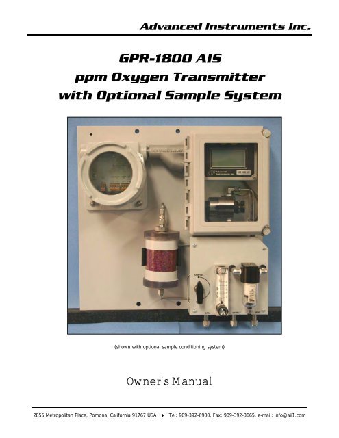
<strong>Advanced</strong> Instruments Inc.<strong>GPR</strong>-<strong>1800</strong> <strong>AIS</strong>ppm <strong>Oxygen</strong> Transmitterwith Optional Sample System(shown with optional sample conditioning system)Owner’s Manual2855 Metropolitan Place, Pomona, California 91767 USA ♦ Tel: 909-392-6900, Fax: 909-392-3665, e-mail: info@aii1.com
<strong>Advanced</strong> Instruments Inc.Table of ContentsIntroduction 1Quality Control Certification 2Safety 3Features & Specifications 4Operation 5Maintenance 6Spare Parts 7Troubleshooting 8Warranty 9Material Safety Data Sheets 10DrawingsA/RExplosion Proofing Electrical Connections Appendix ACorrelating readings – LCD display to 4-20mA signal output Appendix BH2S Scrubber, Sample System, Media MSDS Appendix FMaintenance H2S Scrubber & Coalescing Filter Appendix G1 IntroductionYour new oxygen transmitter incorporated an advanced electrochemical sensor specific to oxygen along with state-of-the-artdigital electronics designed to give you years of reliable precise oxygen measurements in variety of industrial oxygenapplications.To obtain maximum performance from your new oxygen transmitter, please read and follow the guidelines provided in thisOwner’s Manual.Every effort has been made to select the most reliable state of the art materials and components, to design the transmitter forsuperior performance and minimal cost of ownership. This transmitter was tested thoroughly by the manufacturer prior toshipment for best performance.However, modern electronic devices do require service from time to time. The warranty included herein plus a staff of trainedprofessional technicians to quickly service your transmitter is your assurance that we stand behind every transmitter sold.The serial number of this transmitter may be found on the inside the transmitter. You should note the serial number in thespace provided and retains this Owner’s Manual as a permanent record of your purchase, for future reference and for warrantyconsiderations.Serial Number: _______________________<strong>Advanced</strong> Instruments Inc. appreciates your business and pledges to make every effort to maintain the highest possible qualitystandards with respect to product design, manufacturing and service.2
<strong>Advanced</strong> Instruments Inc.2 Quality Control CertificationDate: Customer: Order No.: PassModel: <strong>GPR</strong>-<strong>1800</strong><strong>AIS</strong> ppm <strong>Oxygen</strong> Transmitter S/N __________________Sensor: ( ) <strong>GPR</strong>-12-333 ppm <strong>Oxygen</strong> Sensor( ) XLT-12-333 ppm <strong>Oxygen</strong> Sensor( ) XLT-12-333-F ppm <strong>Oxygen</strong> Sensor S/N __________________Accessories: Owner’s ManualConfiguration: A-1151-<strong>AIS</strong>-1 PCB Assembly Main Processing Software Ver: ___________Power: ( ) A-1166-<strong>AIS</strong>-AC PCB Assembly Alarms/AC Power 110V & Interconnection( ) A-1166-<strong>AIS</strong>-DC PCB Assembly Alarms/DC Power 9-28V & Interconnection( ) A-1153-<strong>AIS</strong>-DC PCB Assembly Alarms/DC Power 9-28V & InterconnectionSPDT relays (B-3208, A-3267, Ex-proof window cover)Ranges: 0-10 ppm, 0-100, 0-1000 ppm, 0-25%Barometric pressure and temperature compensationNEMA 4X rated wall mount enclosuresTest: Pass PassSet default zeroSet default span @ 600uAZero calibrationNoise level < ± 1.0% FSAlarm delayAlarm bypassSpan Calibration Alarm configurations; ALARM 1, ALARM 2Analog signal output 4-20mA full scale Alarm function; ALARM 1, ALARM 2Calibrates with adequate span adjustment within 10-50% FS Alarm relays; ALARM 1, ALARM 2Baseline drift on zero gas < ± 2% FS over 24 hour periodAlarm system fail, dry contactOverall inspection for physical defectsOptions:( x ) A-3393 H2S Scrubber System( x ) MRT-1014 LCD Display Low TemperatureNotes:( x ) HTR-1004 Heater Low Power Sensor Housing3
<strong>Advanced</strong> Instruments Inc.The <strong>GPR</strong>-<strong>1800</strong><strong>AIS</strong> is supplied without a sample conditioning system thereby giving users the option of adding their own orpurchasing a factory designed sample conditioning system. Whatever the choice, the sample must be properly presented to thesensor to ensure an accurate measurement. Users interested in adding their own sample conditioning system should consult thefactory. <strong>Advanced</strong> Instruments Inc. offers a full line of sample handling, conditioning and expertise to meet your applicationrequirements. Contact us at 909-392-6900 or e-mail us at info@aii1.com.Accuracy & CalibrationSingle Point Calibration: As previously describedthe galvanic oxygen sensor generates an electricalcurrent proportional to the oxygen concentration inthe sample gas. In the absence of oxygen the sensorexhibits an absolute zero, e.g. the sensor does notgenerate a current output in the absence of oxygen.Given these linearity and absolute zero properties,single point calibration is possible.Pressure: Because sensors are sensitive to thepartial pressure of oxygen in the sample gas theiroutput is a function of the number of molecules ofoxygen 'per unit volume'. Readouts in percent arepermissible only when the total pressure of thesample gas being analyzed remains constant. Thepressure of the sample gas and that of the calibrationgas(es) must be the same (reality < 1-2 psi).Temperature: The rate oxygen molecules diffuse into the sensor is controlled by a Teflon membrane otherwise known as an'oxygen diffusion limiting barrier' and all diffusion processes are temperature sensitive, the fact the sensor's electrical outputwill vary with temperature is normal. This variation is relatively constant 2.5% per ºC. A temperature compensation circuitemploying a thermistor offsets this effect with an accuracy of +5% or better and generates an output function that isindependent of temperature. There is no error if the calibration and sampling are performed at the same temperature or if themeasurement is made immediately after calibration. Lastly, small temperature variations of 10-15º produce < 1% error.Accuracy: In light of the above parameters, the overall accuracy of an analyzer is affected by two types of errors: 1) thoseproducing 'percent of reading errors', illustrated by Graph A below, such as +5% temperature compensation circuit, tolerancesof range resistors and the 'play' in the potentiometer used to make span adjustments and 2) those producing 'percent of fullscale errors', illustrated by Graph B, such as +1-2% linearity errors in readout devices, which are really minimal due to today'stechnology and the fact that other errors are 'spanned out' during calibration.Graph C illustrates these 'worse case' specifications that are typically used to develop an transmitter's overall accuracystatement of < 1% of full scale at constant temperature or < 5% over the operating temperature range. QC testing is typically< 0.5% prior to shipment.Example 1: As illustrated by Graph A any error, play in the multi-turn span pot or the temperature compensation circuit,during a span adjustment at 20.9% (air) of full scale range would be multiplied by a factor of 4.78 (100/20.9) if used formeasurements of 95-100% oxygen concentrations. Conversely, an error during a span adjustment at 100% of full scale range isreduced proportionately for measurements of lower oxygen concentrations.7
<strong>Advanced</strong> Instruments Inc.Zero Calibration: In theory, the electrochemical galvanic fuel cell type oxygen has an absolute zero meaning it produces nosignal output when exposed to an oxygen free sample gas. In reality, expect the analyzer to generate an oxygen reading whensampling oxygen free sample gas due to contamination or quality of the zero gas; minor leakage in the sample line connections;residual oxygen dissolved in the sensor’s electrolyte; and, tolerances of the electronic components. The Zero Offset capability ofthe analyzer is limited to 50% of lowest most sensitive range available with the analyzer.Recommendation 1: Zero calibration, see Determining True Zero Offset below, is recommended only for online analyzersperforming continuous analysis below 5% of the lowest most sensitive range available with a ppm analyzer, e.g. analysis below0.5 ppm on the 10 ppm range, or below 0.1% (1000 ppm) with a percent analyzer.Note 1: Once the zero offset adjustment is made, zero calibration is not required again until the sample system connections aremodified, or, when installing a new oxygen sensor. As a result, zero calibration is not practical and therefore not recommendedfor higher ranges or portable analyzers.Determining True Zero Offset: Allow the transmitter approximately 24 hours to stabilize with flowing zero gas as evidenced by astable reading or horizontal trend on an external recording device.Note 2: 24 hours is required to assure the sensor has consumed the oxygen that has dissolved into the electrolyte inside thesensor while exposed to air or percentage levels of oxygen. For optimum accuracy, utilize as much of the actual sample systemas possible.Span Calibration: Involves adjusting the transmitter electronics to the sensor’s signal output at a given oxygen standard.Regardless of the oxygen concentration of the oxygen standard used, a typical span calibration takes approximately 10 minutes.Note 3: The amount time required to get the analyzer back on line for normal use is influenced by a.) the level of oxygenanalysis anticipated during normal operation (also determines the initial analyzer selection), and, b.) whether the sensor is newor has been in service for at least two weeks. General guidelines for analyzers to come online following span calibration andexposure to a zero/purge/sample gas with an oxygen content below the stated thresholds:‣ measurements above 1000 ppm or 0.1% require less than 3 minutes‣ measurements above 100 ppm (parts-per-million analyzer) require less than 10 minutes‣ measurements below 10 ppm (part-per-million analyzer) require 20 minutes if the sensor has been in service at ppm levelsfor at least two weeks, and, 60 minutes if the sensor is new assuming the zero/purge/sample gas has an oxygenconcentration below 1 ppmRecommendation 2: For 'optimum calibration accuracy' calibrate with a span gas approximating 80% of the full scale rangeone or two ranges higher than the full scale range of interest (normal use) to achieve the effect illustrated on Graph A andExample 1. Always calibrate at the same temperature and pressure of the sample gas stream.Note 4: Calibrating with a span gas approximating 10% of the full scale range near the expected oxygen concentration of thesample gas is acceptable but less accurate than ‘optimum calibration accuracy’ method recommended – the method usuallydepends on the gas available. Calibrating at the same 10% of the full scale range for measurements at the higher end of therange results in magnification of errors as discussed in Graph A and Example 1 and is not recommended. Of course the user canalways elect at his discretion to accept an accuracy error of +2-3% of full scale range if no other span gas is available.Air Calibration: Based on the inherent linearity of the electrochemical galvanic fuel cell type oxygen sensor enables the user tocalibrate the analyzer with ambient air (20.9% oxygen) and operate the analyzer within the stated accuracy spec on the lowestmost sensitive range available with the analyzer – there is no need to recalibrate the analyzer with span gas containing a loweroxygen concentration. Calibrating either a ppm or percent analyzer with ambient air (with the exception of <strong>Oxygen</strong> Purity<strong>Analyzer</strong>s intended to measure elevated oxygen levels ranging from 50-100% oxygen) on the CAL or 0-25% range meets the80% criteria discussed in Recommendation 2.Recommendation 3: Air calibrate the analyzer (with the exception of <strong>Oxygen</strong> Purity <strong>Analyzer</strong>s intended to measure elevatedoxygen levels ranging from 50-100% oxygen) when operating a percent analyzer, installing and replacing a ppm oxygen sensor,to verify the oxygen content of a certified span gas or when a certified span gas is not available to calibrate a ppm analyzer(immediately following air calibration reintroduce a gas with a low oxygen concentration to expedite the return to ppm levelmeasurements as per Note 3).8
<strong>Advanced</strong> Instruments Inc.Installation ConsiderationsGas Sample Stream: Ensure the gas stream composition of the application is consistent with the specifications and review theapplication conditions before initiating the installation. Consult the factory if necessary to ensure the sample is suitable foranalysis.Note: In natural gas applications such as extraction and transmission, a low voltage current is applied to the pipeline itself toinhibit corrosion. As a result, electronic devices can be affected unless adequately grounded.Contaminant Gases: A gas scrubber and flow indicator with integral metering valve are required upstream of the transmitterto remove interfering gases such as oxides of sulfur and nitrogen or hydrogen sulfide that can produce false readings, reducethe expected life of the sensor and void the sensor warranty if not identified at time of order placement. Installation of asuitable scrubber is required to remove the contaminant from the sample gas to prevent erroneous analysis readings anddamage to the sensor or optional components. Consult the factory for recommendations concerning the proper selection andinstallation of components.Expected Sensor Life: With reference to the publish specification located as the last page of this manual, the expected life ofall oxygen sensors is predicated on oxygen concentration (< 1000 ppm or air), temperature (77°F/25°C) and pressure (1atmosphere) in “normal” applications. Deviations are outside the specifications and will affect the life of the sensor. As a rule ofthumb sensor life is inversely proportional to changes in the parameters.Optimum Accuracy: Determine if Zero Calibration is recommended for your application. If it is Zero Calibration shouldprecede Span Calibration and both should be repeated after the analyzer has been allowed to stabilize, typically 24-36 hoursafter installation. For Span Calibration use a certified span gas with an oxygen content (balance nitrogen) approximating 80% ofthe next higher full scale range above the intended measuring range is recommended for optimum accuracy, see Calibrationand Accuracy.Assuming the initial zero is performed according to the procedure described herein, the analyzer should not require ZeroCalibration again until the either the sensor is replaced or a change is made to the sample system or gas lines, and, it shouldnot require Span Calibration again for up to 3 months under “normal” application conditions as described in the publishedspecifications. One of the unique features of analyzers based on the electrochemical galvanic fuel cell type oxygen sensor is thefact that it can be field calibrated at the user’s discretion to whatever standard of certified span gas the user elects to use.Zero Calibration: In theory, the oxygen sensor produces no signal output when exposed to an oxygen free sample gas. Inreality, expect the transmitter to generate an oxygen reading when sampling oxygen free sample gas due to contamination orquality of the zero gas; minor leakage in the sample line connections; residual oxygen dissolved in the sensor’s electrolyte; and,tolerances of the electronic components.Zero calibration, see Determining True Zero Offset below, is recommended only for online analyzers performing continuousanalysis below 5% of the lowest most sensitive range available with a ppm analyzer, e.g. analysis below 0.5 ppm on the 10 ppmrange, or below 0.1% (1000 ppm) with a percent analyzer. Note : Once the zero offset adjustment is made, zero calibration isnot required again until the sample system connections are modified, or, when installing a new oxygen sensor. As a result, zerocalibration is not practical and therefore not recommended for higher ranges or portable analyzers.Determining True Zero Offset: Allow the transmitter approximately 24 hours to stabilize with flowing zero gas as evidenced by astable reading or horizontal trend on an external recording device. Note: 24 hours is required to assure the sensor hasconsumed the oxygen that has dissolved into the electrolyte inside the sensor while exposed to air or percentage levels ofoxygen. For optimum accuracy, utilize as much of the actual sample system as possible.Span Calibration: Involves adjusting the transmitter electronics to the sensor’s signal output at a given oxygen standard, e.g.a certified span gas with an oxygen content (balance nitrogen) approximating 80% of the next higher full scale range above theintended measuring range is recommended for optimum accuracy, see Calibration and Accuracy.9
<strong>Advanced</strong> Instruments Inc.Recommendation: Based on the inherent linearity of the galvanic oxygen sensor enables the user to calibrate the analyzerwith ambient air (20.9% oxygen) and operate the analyzer within the stated accuracy spec on the lowest most sensitive rangeavailable with the analyzer – there is no need to recalibrate the analyzer with span gas containing a lower oxygenconcentration.Calibrating either a ppm or percent analyzer with ambient air (with the exception of <strong>Oxygen</strong> Purity <strong>Analyzer</strong>s intended tomeasure elevated oxygen levels ranging from 50-100% oxygen) on the CAL or 0-25% range meets the 80% criteria discussedabove. Air calibrate the analyzer (with the exception of <strong>Oxygen</strong> Purity <strong>Analyzer</strong>s intended to measure elevated oxygen levelsranging from 50-100% oxygen) when operating a percent analyzer, installing and replacing a ppm oxygen sensor, to verify theoxygen content of a certified span gas or when a certified span gas is not available to calibrate a ppm analyzer (immediatelyfollowing air calibration reintroduce a gas with a low oxygen concentration to expedite the return to ppm level measurements).Materials: Assemble the necessary zero, purge and span gases and optional components such as valves, coalescing orparticulate filters, and, pumps as dictated by the application; stainless steel tubing is essential for maintaining the integrity ofthe gas stream for ppm and percentage range (above or below ambient air) analysis; hardware for mounting.Temperature: The sample must be sufficiently cooled before it enters the transmitter and any optional components. A coiled10 foot length of ¼” stainless steel tubing is sufficient for cooling sample gases as high as 1,800ºF to ambient.Pressure & FlowAll electrochemical oxygen sensors respond to partial pressure changes in oxygen. The sensors are equallycapable of analyzing the oxygen content of a flowing sample gas stream or monitoring the oxygenconcentration in ambient air (such as a confined space such in a control room or an open area such as alandfill or bio-pond).Sample systems and/or flowing gas samples are generally required for applications involving oxygenmeasurements at levels other than ambient air and when the pressure exceeds ambient. In thesesituations, the use of stainless steel tubing and fittings is critical to maintaining the integrity of the gasstream to be sampled and the inlet pressure must always be higher than the pressure at the outlet ventwhich is normally at atmospheric pressure.Flow Through Configuration: The sensor is exposed to sample gas that must flow or be drawn throughmetal tubing inside the transmitter. The internal sample system includes 1/8” compression inlet and ventfittings, a stainless steel sensor housing with an o-ring seal to prevent the leakage of air and stainlesssteel tubing.Flow rates of 1-5 SCFH cause no appreciable change in the oxygen reading. However, flow rates above 5 SCFH generatebackpressure and erroneous oxygen readings because the diameter of the integral tubing cannot evacuate the sample gas atthe higher flow rate. The direction the sample gas flows is not important, thus either tube fitting can serve as the inlet or vent –just not simultaneously.A flow indicator with an integral metering valve upstream of the sensor is recommended as a means of controlling the flow rateof the sample gas. A flow rate of 2 SCFH or 1 liter per minute is recommended for optimum performance.Caution: Do not place your finger over the vent (it pressurizes the sensor) to test the flow indicator when gas is flowing to thesensor. Removing your finger (the restriction) generates a vacuum on the sensor and may damage the sensor (voiding thesensor warranty). To avoid generating a vacuum on the sensor (as described above) during operation, always select and installthe vent fitting first and remove the vent fitting last.Application Pressure - Positive: A flow indicator with integral metering valve positioned upstream of the sensor isrecommended for controlling the sample flow rate between 1-5 SCFH. To reduce the possibility of leakage for low ppmmeasurements, position a metering needle valve upstream of the sensor to control the flow rate and position a flow indicatordownstream of the sensor. If necessary, a pressure regulator (with a metallic diaphragm is recommended for optimumaccuracy, the use of diaphragms of more permeable materials may result in erroneous readings) upstream of the flow controlvalve should be used to regulate the inlet pressure between 5-30 psig.Caution: If equipped with a H2S scrubber, inlet pressure must not exceed 30 psig.10
<strong>Advanced</strong> Instruments Inc.Application Pressure - Atmospheric or Slightly Negative: For accurate ppm range oxygen measurements, an optionalexternal sampling pump should be positioned downstream of the sensor to draw the sample from the process, by the sensorand out to atmosphere. A flow meter is generally not necessary to obtain the recommended flow rate with most samplingpumps.Caution: If the transmitter is equipped with an optional flow indicator with integral metering valve or a metering flow controlvalve upstream of the sensor - open the metering valve completely to avoid drawing a vacuum on the sensor and placing anundue burden on the pump.If pump loading is a consideration, a second throttle valve on the pump’s inlet side may be necessary to provide a bypass pathso the sample flow rate is within the above parameters.Recommendations to avoid erroneous oxygen readings and damaging the sensor:‣ Do not place your finger over the vent (it pressurizes the sensor) to test the flow indicator when gas is flowing to thesensor. Removing your finger (the restriction) generates a vacuum on the sensor and may damage the sensor (voiding thesensor warranty).‣ Assure there are no restrictions in the sample or vent lines‣ Avoid drawing a vacuum that exceeds 14” of water column pressure – unless done gradually‣ Avoid excessive flow rates above 5 SCFH which generate backpressure on the sensor.‣ Avoid sudden releases of backpressure that can severely damage the sensor.‣ Avoid the collection of liquids or particulates on the sensor, they block the diffusion of oxygen into the sensor.‣ If the transmitter is equipped with an optional integral sampling pump (positioned downstream of the sensor) and a flowcontrol metering valve (positioned upstream of the sensor), completely open the flow control metering valve to avoiddrawing a vacuum on the sensor and placing an undue burden on the pump.Moisture & Particulates: Installation of a suitable coalescing or particulate filter is required to remove condensation, moistureand/or particulates from the sample gas to prevent erroneous analysis readings and damage to the sensor or optionalcomponents. Moisture and/or particulates do not necessarily damage the sensor, however, collection on the sensing surfacecan block or inhibit the diffusion of sample gas into the sensor resulting in a reduction of sensor signal output – and theappearance of a sensor failure when in fact the problem is easily remedied by blowing on the front of the sensor. Consult thefactory for recommendations concerning the proper selection and installation of components.Gas Connections: Inlet and outlet vent gas lines for ppm analysis require 1/8” or ¼” stainless steel compression fittings; hardplastic tubing with a low permeability factor can be used percentage range measurements.Power Connection: Locate the appropriate power source to meet the analyzer or transmitter requirements, ensure that isproperly grounded and meets the area classification.Mounting the TransmitterThe <strong>GPR</strong>-<strong>1800</strong><strong>AIS</strong> consists of two interconnected enclosures (without the optionalsample conditioning system and panel) and measures 8”H x 15-3/4”W x 7”D. Thisconfiguration is designed to be mounted directly to any flat vertical surface, wall orbulkhead plate with eight (8) of the appropriate screws. To facilitate servicing theinterior of the transmitters, position it approximately 5 feet off ground level.Remove the four (4) screws securing the top section of the enclosure, set themaside for reinstallation and raise the hinged top section 180º until it locks in place.Locate the mounting holes cast into the enclosure.Secure the enclosure to a vertical surface approximately 5 feet from the floor or a level accessible to service personnel. Thisrequires the user to supply four (4) additional proper size screws and anchors.Caution: Do not remove or discard the gaskets from either the enclosure or junction box. Failure to reinstall either gasket willvoid the NEMA 4 rating and RFI protection. The transmitters design provides protection from RFI that is maintained by leavingspecific mating areas of the enclosure unpainted to maintain conductivity the gasket, top and bottom sections of the enclosure.11
<strong>Advanced</strong> Instruments Inc.These unpainted areas are protected by gaskets and contribute to maintaining the NEMA 4 rating. Do not paint these areas.Painting will negate the RFI protection.Note: If equipped with the optional H2S sample conditioning system, the transmitter and sample system are mounted to a backpanel which has four (4) holes for mounting the 15-3/4”H x 15-3/4”W x 7”D panel to any vertical flat surface.Gas ConnhectionsThe <strong>GPR</strong>-<strong>1800</strong><strong>AIS</strong> with its standard flow through configuration is designed for positive pressure samples and requiresconnections for incoming sample and outgoing vent lines. Zero and span inlet ports are offered as part of the optional samplesystems. The user is responsible for calibration gases and the required components, see below.Flow rates of 1-5 SCFH cause no appreciable change in the oxygen reading. However, flow rates above 5 SCFH generatebackpressure and erroneous oxygen readings because the diameter of the integral tubing cannot evacuate the sample gas atthe higher flow rate. A flow indicator with an integral metering valve upstream of the sensor is recommended as a means ofcontrolling the flow rate of the sample gas. A flow rate of 2 SCFH or 1 liter per minute is recommended for optimumperformance.Caution: Do not place your finger over the vent (it pressurizes the sensor) to test the flow indicator when gas is flowing to thesensor. Removing your finger (the restriction) generates a vacuum on the sensor and may damage the sensor (voiding thesensor warranty).Procedure:1. Caution: Do not change the factory setting until instructed to do in this manual.2. Designate one of the bulkhead tube fittings as the VENT and the other SAMPLE.3. Regulate the pressure as described in Pressure and Flow above.4. Connect a 1/8” vent line to the compression fitting to be used for venting the sample.5. Connect a 1/8” ZERO, SPAN or SAMPLE line to the fitting designated SAMPLE.6. If equipped with optional fittings and/or sample system, connect the ZERO and SPAN gas lines.7. Allow gas to flow through the transmitters and set the flow rate to 2 SCFH.8. Note: If equipped with the optional H2S sample conditioning system: Regulate the pressure so that it does not exceed30 psig use ¼” tubing to make the appropriate connections as labeled on the sample panel.Electrical ConnectionsIncoming power, power failure and set point alarm, and, output connections aremade to a terminal block mounted on a PCB located in the lower explosion proofenclosure.The PCB also includes a transformer to power the alarm relays and intrinsicsafety barriers that limited the amount of voltage going to the upper electronicsenclosure. With proper insulation of the incoming power (see Appendix A), thisconfiguration the <strong>GPR</strong>-<strong>1800</strong><strong>AIS</strong> meets the intrinsic safety standards for use inClass 1, Division 1, Groups A-D hazardous areas.Caution: The integral 4-20mA converter is internally powered and does notrequire external power. DO NOT supply any voltage to either of the twoterminals of the 4-20mA output or the 4-20mA converter will be damaged.To assure proper grounding, connect the 4-20mA signal output to the external device (PLC, DCS, etc.) before attempting anyzero or span adjustments.Procedure:Power requirements consist of a two wire shielded cable and a 12-28V DC with negative ground power supply.1. Unscrew the cone shaped cover from the lower enclosure.2. Separate the shielding from the wires of the cable.12
<strong>Advanced</strong> Instruments Inc.3. Ensure the positive and negative terminals of the power supply are connected to the appropriate terminals of the barrierstrip as marked.4. Connect the shielding of the cable to the ground screw inside the enclosure. Note: The terminals snap together, making itpossible to detach the section with the ground, install the shielded cable and reinstall.5. Replace the cover.6. The 4-20mA current output is obtained by connecting the current measuring device between the positive and negativeterminals labeled OUTPUT 4-20mA.7. To check the signal output of the 4-20mA E/I integrated circuit connect an ammeter as the measuring device and confirmthe output is within +0.1mA of 4mA.8. Caution: To assure proper grounding, connect the 4-20mA signal output to the external device (PLC, DCS, etc.) beforeattempting any zero or span adjustments.Installing the <strong>Oxygen</strong> SensorThe <strong>GPR</strong>-<strong>1800</strong><strong>AIS</strong> ppm <strong>Oxygen</strong> Transmitter is equipped with an integral oxygen sensor.They have been tested and calibrated by the manufacturer prior to shipment and are fullyoperational from the shipping container.Caution: All transmitters must be calibrated once the installation has been completed andperiodically thereafter as described below. Following the initial installation and calibration,allow the transmitters to stabilize for 24 hours and calibrate with certified span gas.Caution: DO NOT open the oxygen sensor. The sensor contains a corrosive liquidelectrolyte that could be harmful if touched or ingested, refer to the Material Safety Data Sheet contained in the Owner’sManual appendix. Avoid contact with any liquid or crystal type powder in or around the sensor orsensor housing, as either could be a form of electrolyte. Leaking sensors should be disposed of inmanner similar to that of a common battery in accordance with local regulations.Procedure:1. The sensor has not been installed at the factory (in standard configuration there are no valvesto isolate the sensor) and it will be necessary to install the sensor in the field.2. Caution: Do not change the factory settings until instructed to do in this manual.3. Connect the gas lines as previously described.4. Purge the oxygen trapped in the newly connected gas lines for 3-5 minutes.5. Flow zero gas or sample gas with a low ppm oxygen concentration to the analyzer at thepredetermined flow rate of 2 SCFH.6. Using the 5/16 wrench supplied loosen but do not remove the clamp bolt located under thesensor housing, see photo.7. Rotate the upper section of the sensor housing 90º to disengage from the clamp.8. Remove the upper section by pulling it straight up and place it on a smooth surface.9. Select the AUTO RANGING option from the SAMPLE menu with gas flowing to the analyzer.10. Remove the oxygen sensor from the bag and remove the red shorting device (including the gold ribbon) from the PCBlocated at the rear of the sensor. Minimize the time the sensor is exposed to ambient air.11. Immediately place the sensor in the bottom section of the sensor housing with the PCB facing up.12. Immediately place the upper section of the sensor housing over the sensor, gently push the upper section downward androtate 90º to engage the clamp.13. Finger tighten the clamp bolt and then tighten it one full turn with the 5/16 wrench to securely lock the two sections of thesensor housing.14. The analyzer will OVER RANGE for a short period of time as indicated by the graphical LCD display.15. Wait until the display shows a meaningful oxygen reading and begins to approach the expected oxygen content of thesample gas.Span Gas PreparationCaution: Do not contaminate the span gas cylinder when connecting the regulator. Bleed the air filled regulator (faster andmore reliable than simply flowing the span gas) before attempting the initial calibration of the instrument.13
<strong>Advanced</strong> Instruments Inc.Required components:1. Certified span gas cylinder with an oxygen concentration, balance nitrogen, approximating 80% of the full scale rangeabove the intended measuring range.2. Regulator to reduce pressure to between 5 and 30 psig.3. Flow meter to set the flow between 1-5 SCFH,4. Suitable fittings and a 4-6 ft. in length of 1/8” dia. metal tubing to connect the regulator to the flow meter inlet5. Suitable fitting and a 4-6 ft. in length of 1/8” dia. metal tubing to connect from the flow meter vent to tube fittingdesignated SAMPLE IN on the <strong>GPR</strong>-1200.Procedure:1. With the span gas cylinder valve closed, install the regulator on the cylinder.2. Open the regulator’s exit valve and partially open the pressure regulator’s control knob.3. Open slightly the cylinder valve.4. Loosen the nut connecting the regulator to the cylinder and bleed the pressure regulator.5. Retighten the nut connecting the regulator to the cylinder6. Adjust the regulator exit valve and slowly bleed the pressure regulator.7. Open the cylinder valve completely.8. Set the pressure between 5-30 psig using the pressure regulator’s control knob.9. Caution: Do not exceed the recommended flow rate. Excessive flow rate could cause the backpressure on the sensor andmay result in erroneous readings and permanent damage to the sensor.Establishing Power to the ElectronicsOnce the two wires of the shielded cable are properly connected to the terminals inside the junction box as described above,connect the other end of the two wires to a suitable 12-28V DC power supply with negative ground such as a PLC, DCS, etc.The digital display responds instantaneously. When power is applied, the transmitter performs several diagnostic system statuschecks termed “START-UP TEST” as illustrated below:START-UP TESTELECTRONICS – PASSTEMP SENSOR – PASSBAROMETRIC SENSOR – PASSREV. 1.61Note: The transmitter display defaults to the sampling mode when 30 seconds elapses without user interface.Menu Navigation3.3 <strong>PPM</strong>AUTO SAMPLING10 <strong>PPM</strong> RANGE24.5 C 100 KPALO1 2<strong>PPM</strong>10<strong>PPM</strong> HI2The four (4) pushbuttons located on the front of the transmitter operate the micro-processor:1. blue ENTER (select)2. yellow UP ARROW14
<strong>Advanced</strong> Instruments Inc.3. yellow DOWN ARROW4. green MENU (escape)Main MenuAccess the MAIN MENU by pressing the MENU key:MAIN MENUAUTO SAMPLEMANUAL SAMPLECALIBRATIONCONFIG ALARMSBYPASS ALARMSRange SelectionThe <strong>GPR</strong>-<strong>1800</strong><strong>AIS</strong> transmitter is equipped with five (5) standard measuring ranges (see specification) and provides users with achoice of sampling modes. By accessing the MAIN MENU, users may select either the AUTO SAMPLING (ranging) or MANUALSAMPLING (to lock on a single range) mode.Note: For calibration purposes, use of the AUTO SAMPLE mode is recommended. However, the user can select the full scaleMANUAL SAMPLE RANGE for calibration as dictated by the accuracy of the analysis required – for example, a span gas with an80 ppm oxygen concentration with the balance nitrogen would dictate the use of the 0-100 ppm full scale range for calibrationand a 0-10 ppm measuring range.Auto Sampling:1. Access the MAIN MENU by pressing the MENU key.2. Advance the reverse shade cursor using the ARROW keys to highlight AUTO SAMPLE.3. Press the ENTER key to select the highlighted menu option.4. The display returns to the sampling mode:MAIN MENUAUTO SAMPLEMANUAL SAMPLECALIBRATIONCONFIG ALARMSBYPASS ALARMS3.3 <strong>PPM</strong>AUTO SAMPLING10 <strong>PPM</strong> RANGE24.5 C 100 KPALO1 2<strong>PPM</strong>10<strong>PPM</strong> HI2The display will shift to the next higher range when the oxygen reading (actually the sensor’s signal output) exceeds 99.9% ofthe upper limit of the current range. The display will shift to the next lower range when the oxygen reading drops to 85% of theupper limit of the next lower range.For example, if the transmitter is reading 1% on the 0-10% range and an upset occurs, the display will shift to the 0-25% rangewhen the oxygen reading exceeds 9.9%. Conversely, once the upset condition is corrected, the display will shift back to the 0-10% range when the oxygen reading drops to 8.5%.Manual Sampling:1. Access the MAIN MENU by pressing the MENU key.15
<strong>Advanced</strong> Instruments Inc.2. Advance the reverse shade cursor using the ARROW keys to highlight MANUAL SAMPLE.3. Press the ENTER key to select the highlighted menu option.4. The following display appears:MAIN MENUAUTO SAMPLEMANUAL SAMPLECALIBRATIONCONFIG ALARMSBYPASS ALARMS>>>MANUAL RANGE25%1%1000 <strong>PPM</strong>100 <strong>PPM</strong>10 <strong>PPM</strong>5. Advance the reverse shade cursor using the ARROW keys to highlight the desired MANUAL RANGE.6. Press the ENTER key to select the highlighted menu option.7. The following displays appears with the range selected and oxygen concentration of the sample gas:MANUAL RANGE25%1%1000 <strong>PPM</strong>100 <strong>PPM</strong>10 <strong>PPM</strong>>>>3.3<strong>PPM</strong>MANUAL SAMPLING10 <strong>PPM</strong> RANGE24.5 C 100 KPALO1 2<strong>PPM</strong>10<strong>PPM</strong> HI2The display will not shift automatically. Instead, when the oxygen reading (actually the sensor’s signal output) exceeds 110% ofthe upper limit of the current range an OVER RANGE warning will be displayed.Note: 3.3 <strong>PPM</strong> displayed on ranges of 1000 <strong>PPM</strong> and below, 0.0% displayed on ranges of 1% and above.3.3 <strong>PPM</strong>OVERRANGEMANUAL SAMPLING1000 <strong>PPM</strong> RANGE24.5 C 100 KPALO1 2<strong>PPM</strong>10<strong>PPM</strong> HI2Once the OVER RANGE warning appears the user must advance the transmitter to the next higher range via the menu andkeypad Press MENU, select MANUAL SAMPLING, press ENTER, select the appropriate MANUAL RANGE and press ENTER again.16
<strong>Advanced</strong> Instruments Inc.AlarmsThe CONFIG ALARMS features a system that can be configured in the field. Two field adjustable alarm relays with dry contactsoperate independently of one another which means the alarms can be set-up as:‣ HI and LO‣ LO and LO, LO,‣ HI and HI,HI‣ PERCENT (of full scale range which changes with auto-ranging)‣ % (oxygen value)Additional feature includes delaying the activation of the local audible alarm and relay contacts for up 99 minutes to enableusers to distinguish between transient occurrences and true upset conditions which is particularly useful on remote applicationswithout affecting the 4-20mA signal output. The local audible alarm can be silenced or disabled as well without affecting the 4-20mA signal output.Note: A separate feature, BYPASS ALARMS described below, enables the user to disable the local audible alarm and relaycontacts during calibration or servicing. The alarms are enabled when the alarm condition is corrected.Set Alarm Values:1. Access the MAIN MENU by pressing the MENU key.2. Advance the reverse shade cursor using the ARROW keys to highlight CONFIG ALARMS.3. Press the ENTER key to select the highlighted menu option.4. The following displays appears:MAIN MENUAUTO SAMPLEMANUAL SAMPLECALIBRATIONCONFIG ALARMSBYPASS ALARMS>>>MAIN MENUSET ALARM 1SET ALARM 2SET ALARM DELAYALARM 1 HI/LOALARM 2 HI/LOALARMS AUDIBLE/SILENT5. Advance the reverse shade cursor using the ARROW keys to highlight the SET ALARM 1 option.6. Press the ENTER key to select the highlighted menu option.7. The following displays appears with PERCENT as the default alarm value :MAIN MENUSET ALARM 1SET ALARM 2SET ALARM DELAYALARM 1 HI/LOALARM 2 HI/LOALARMS AUDIBLE/SILENT>>>GAS CONCENTRATIONPERCENT<strong>PPM</strong>8. Advance the reverse shade cursor using the ARROW keys to highlight the desired option.17
<strong>Advanced</strong> Instruments Inc.9. Press the ENTER key to select the highlighted menu option.Note: The PERCENT (of FS) alarm value is entered with one decimal, the <strong>PPM</strong> (oxygen) alarm value is entered as an integer.GAS CONCENTRATIONPERCENT<strong>PPM</strong>>>>01.0SET ALARM 1 VALUEPRESS UP OR DOWNTO CHANGE VALUEENTER TO SAVEMENU TO RETURNGAS CONCENTRATIONPERCENT<strong>PPM</strong>>>>002SET ALARM 1 VALUEPRESS UP OR DOWNTO CHANGE VALUEENTER TO SAVEMENU TO RETURN10. Press the ENTER key to advance the underline cursor right or press the MENU key to advance the underline cursor left toreach to the desired digit of the alarm value.11. Press the ARROW keys to enter the alarm value.12. Repeat until the complete span value has been entered.13. Note: If an alarm is set as a PERCENT value and subsequently changed to a <strong>PPM</strong> value, the PERCENT value is not retainedand is reset to 00.0. This holds if the alarm was first set as <strong>PPM</strong> value and then changed to a PERCENT value.14. Save the alarm value by pressing the ENTER key or abort by pressing the MENU key.15. The system returns to the SAMPLING mode and displays:3.3 <strong>PPM</strong>AUTO SAMPLING10 <strong>PPM</strong> RANGE24.5 C 100 KPALO1 2<strong>PPM</strong>10<strong>PPM</strong> HI2Repeat the steps above to set the ALARM 2 value:MAIN MENUAUTO SAMPLEMANUAL SAMPLECALIBRATIONCONFIG ALARMSBYPASS ALARMS>>>MAIN MENUSET ALARM 1SET ALARM 2SET ALARM DELAYALARM 1 HI/LOALARM 2 HI/LOALARMS AUDIBLE/SILENTSet Alarm Delay:18
<strong>Advanced</strong> Instruments Inc.Once the values for ALARM 1 and ALARM 2 have been entered, the user may elect to delay the activation of the local alarmsand relay contacts for up to 99 minutes. This feature allows users to distinguish between transient occurrences and true upsetconditions. This feature can be particularly useful on remote applications without affecting the 4-20mA signal output.1. Access the MAIN MENU by pressing the MENU key.2. Advance the reverse shade cursor using the ARROW keys to highlight CONFIG ALARMS.3. Press the ENTER key to select the highlighted menu option.4. The following displays appear:MAIN MENUAUTO SAMPLEMANUAL SAMPLECALIBRATIONCONFIG ALARMSBYPASS ALARMS>>>MAIN MENUSET ALARM 1SET ALARM 2SET ALARM DELAYALARM 1 HI/LOALARM 2 HI/LOALARMS AUDIBLE/SILENT5. Advance the reverse shade cursor using the ARROW keys to highlight the SET ALARM DELAY.6. Press the ENTER key to select the highlighted menu option.7. The following displays appear with last alarm delay value :MAIN MENUSET ALARM 1SET ALARM 2SET ALARM DELAYALARM 1 HI/LOALARM 2 HI/LOALARMS AUDIBLE/SILENT>>>99DELAY IN MINUTESPRESS UP OR DOWNTO CHANGE VALUEENTER TO SAVEMENU TO RETURN8. Press the ENTER key to advance the underline cursor right or press the MENU key to advance the underline cursor left toreach to the desired digit of the alarm value.9. Press the ARROW keys to enter the alarm value.10. Repeat until the complete span value has been entered.11. Save the alarm value by pressing the ENTER key or abort by pressing the MENU key.12. The system returns the SAMPLING mode and displays:3.3 <strong>PPM</strong>AUTO SAMPLING10 <strong>PPM</strong> RANGE24.5 C 100 KPALO1 2<strong>PPM</strong>10<strong>PPM</strong> HI2Set HI/LO Alarms:1. Access the MAIN MENU by pressing the MENU key.2. Advance the reverse shade cursor using the ARROW keys to highlight CONFIG ALARMS.19
<strong>Advanced</strong> Instruments Inc.3. Press the ENTER key to select the highlighted menu option.4. The following displays appears:MAIN MENUAUTO SAMPLEMANUAL SAMPLECALIBRATIONCONFIG ALARMSBYPASS ALARMS>>>MAIN MENUSET ALARM 1SET ALARM 2SET ALARM DELAYALARM 1 HI/LOALARM 2 HI/LOALARMS AUDIBLE/SILENT5. Advance the reverse shade cursor using the ARROW keys to highlight the ALARM 1 option, which appears as either ALARM1 HI or ALARM 1 LO.6. Press the ENTER key to toggle and change the displayed setting. After 3 seconds, the system returns to SAMPLING mode.3.3 <strong>PPM</strong>AUTO SAMPLING10 <strong>PPM</strong> RANGE24.5 C 100 KPALO1 2<strong>PPM</strong>10<strong>PPM</strong> HI27. Repeat steps 1 through 6 for the ALARM 2 HI/LO setting.Set Local Alarms:1. Access the MAIN MENU by pressing the MENU key.2. Advance the reverse shade cursor using the ARROW keys to highlight CONFIG ALARMS.3. Press the ENTER key to select the highlighted menu option.4. The following displays appears:MAIN MENUAUTO SAMPLEMANUAL SAMPLECALIBRATIONCONFIG ALARMSBYPASS ALARMS>>>MAIN MENUSET ALARM 1SET ALARM 2SET ALARM DELAYALARM 1 HI/LOALARM 2 HI/LOALARMS AUDIBLE/SILENT5. Advance the reverse shade cursor using the ARROW keys to highlight the ALARMS AUDIBLE/SILENT option, which appearas either ALARMS AUDIBLE or ALARMS SILENT.6. Press the ENTER key to toggle and change the displayed setting. After 3 seconds, the system returns to SAMPLING mode.20
<strong>Advanced</strong> Instruments Inc.3.3 <strong>PPM</strong>AUTO SAMPLING10 <strong>PPM</strong> RANGE24.5 C 100 KPALO1 2<strong>PPM</strong>10<strong>PPM</strong> HI2Bypass Alarms:This feature, separate from CONFIG ALARMS above, enables the user to disable the local audible alarm and relay contactsduring calibration or servicing. The alarms are enabled when the alarm condition is corrected.1. Access the MAIN MENU by pressing the MENU key.2. Advance the reverse shade cursor using the ARROW keys to highlight BYPASS ALARMS.3. The following displays appears:MAIN MENUAUTO SAMPLEMANUAL SAMPLECALIBRATIONCONFIG ALARMSBYPASS ALARMS4. Press the ENTER key to bypass and disable both the local audible alarm and relay contacts. After 3 seconds, the systemreturns to SAMPLING mode.5. Note: The appropriate alarm setting will alternately reverse shades indicating the alarm condition exists but the BYPASSALARMS feature has disabled the local audible alarm and relay contact. The alarms are enabled when the alarm condition iscorrected.3.3 <strong>PPM</strong>AUTO SAMPLING10 <strong>PPM</strong> RANGE24.5 C 100 KPALO1 2<strong>PPM</strong>10<strong>PPM</strong> HI2Start-Up is complete . . . proceed to Calibration21
<strong>Advanced</strong> Instruments Inc.Zero CalibrationIn theory, the oxygen sensor produces no signal output when exposed to an oxygen free sample gas. However, the transmitterwill generate an oxygen reading when sampling oxygen free sample gas due to:‣ Contamination or quality of the zero gas‣ Minor leakage in the sample line connections‣ Residual oxygen dissolved in the sensor’s electrolyte‣ Tolerances of the electronic componentsRecommendation: Zero calibration is recommended only for online analyzers intended for measurements below 1 ppm on the10 ppm range and then only when the sample system connections are modified and when installing a new oxygen sensor. It isnot practical on higher ranges or portable analyzers for the following reasons:1. Determining the true zero offset reguires the user allow the analyzer approximately 24 hours to stabilize with flowing zerogas as evidenced by a stable reading with no downward trend on an external recording device. Note: Approximately 24-36hours is required to assure the sensor has consumed the oxygen that has dissolved into the electrolyte inside the sensorwhile exposed to air or percentage levels of oxygen. For optimum accuracy, utilize as much of the actual sample system aspossible.2. Thus it is not practical to find the true zero offset particularly in the case of applications requiring higher level oxygenmeasurements because of the low offset value, normally 50% of the most sensitive range, is not material to the accuracyof higher level measurements. Nor is it practical to zero a portable analyzer every time it is moved from one sample pointto another.3. Caution: Prematurely zeroing the analyzer can cause a negative reading in both the ZERO and SAMPLE modes.4. Satisfying users that the zero offset is reasonably acceptable for their application can be accomplished much quicker.Unless the zero gas is contaminated or there is a significant leak in the sample connections, the analyzer should read lessthan 100 ppm oxygen within 10 minutes after being placed on zero gas thereby indicating it is operating normally.Recommendation: Initiate the DEFAULT ZERO procedure before performing either a ZERO or SPAN CALIBRATION.Procedure:Zero calibration should precede the span calibration and once performed should not have to be repeated with subsequent spancalibrations. Normally, zero calibrations are performed when a new sensor is installed or changes are made in the samplesystem connections.Refer to Span Calibration below for the detailed procedure. Differences include the displays illustrated below, substituting asuitable zero gas for the span gas and the time required to determine the true zero offset of specific oxygen sensor, analyzerand sample system combination.The maximum zero calibration adjustment permitted is 50% of the lowest full scale analysis range available. Accordingly, theanalyzer’s ZERO has not been adjusted prior to shipment because the factory conditions are different from the applicationcondition at the user’s installation.1. Access the MAIN MENU by pressing the MENU key.2. Advance the reverse shade cursor using the ARROW keys to highlight CALIBRATION.3. Press the ENTER key to select the highlighted menu option.4. The following displays appear:MAIN MENUAUTO SAMPLEMANUAL SAMPLECALIBRATIONCONFIG ALARMSBYPASS ALARMS>>>CALIBRATIONSPAN CALIBRATEZERO CALIBRATEDEFAULT SPANDEFAULT ZEROOUTPUT SPANOUTPUT ZERO5. Advance the reverse shade cursor using the ARROW keys to highlight ZERO CALIBRATE.22
<strong>Advanced</strong> Instruments Inc.6. Press the ENTER key to select the highlighted menu option.7. The following displays appear:0.000 <strong>PPM</strong>ZEROCALIBRTIONENTER TO CALIBRATEMENU TO ABORT8. Press the ENTER key to calibrate or MENU key to abort and return to SAMPLING mode.9. Allow approximately 60 seconds for the calibration process while the processor determines whether the signal output orreading has stabilized within 60% of the full scale low range.10. Both the Zero Calibrate and Span Calibrate functions result in the following displays:PASSEDCALIBRATIONORFAILEDCALIBRATIONThe maximum zero calibration adjustment permitted is 50% of the lowest full scale range available. Accordingly, thetransmitter’s ZERO has not been adjusted prior to shipment because the factory conditions are different from the applicationcondition at the user’s installation.Default ZeroThe software will eliminate any previous zero calibration adjustment and display the actual the signal output of the sensor at aspecified oxygen concentration. For example, assuming a zero gas is introduced, the display will reflect an oxygen readingrepresenting basically the zero calibration adjustment as described above. This feature allows the user to test the sensor’s signaloutput without removing it from the sensor housing.Recommendation: Initiate the DEFAULT ZERO procedure before performing either a ZERO or SPAN CALIBRATION.1. Access the MAIN MENU by pressing the MENU key.2. Advance the reverse shade cursor using the ARROW keys to highlight CALIBRATION.3. Press the ENTER key to select the highlighted menu option.4. The following displays appear:MAIN MENUAUTO SAMPLEMANUAL SAMPLECALIBRATIONCONFIG ALARMSBYPASS ALARMS>>>CALIBRATIONSPAN CALIBRATEZERO CALIBRATEDEFAULT SPANDEFAULT ZEROOUTPUT SPANOUTPUT ZERO5. Advance the reverse shade cursor using the ARROW keys to highlight DEFAULT ZERO.6. Press the ENTER key to select the highlighted menu option.23
<strong>Advanced</strong> Instruments Inc.7. The following display appears and after 3 seconds the system returns to the SAMPLING mode:FACTORYDEFAULTSSET3.3 <strong>PPM</strong>AUTO SAMPLING10 <strong>PPM</strong> RANGE24.5 C 100 KPALO1 2<strong>PPM</strong>10<strong>PPM</strong> HI2Output ZeroIn rare instances the 4-20mA signal output may not agree to the reading displayed by the LCD. This feature enables the user toadjust the 4mA signal output when the LCD displays 00.00. Note: Adjust the 20mA signal output with the OUTPUT SPAN.1. Access the MAIN MENU by pressing the MENU key.2. Advance the reverse shade cursor using the ARROW keys to highlight CALIBRATION.3. Press the ENTER key to select the highlighted menu option.4. The following displays appear:MAIN MENUAUTO SAMPLEMANUAL SAMPLECALIBRATIONCONFIG ALARMSBYPASS ALARMS>>>CALIBRATIONSPAN CALIBRATEZERO CALIBRATEDEFAULT SPANDEFAULT ZEROOUTPUT SPANOUTPUT ZERO5. Advance the reverse shade cursor using the ARROW keys to highlight DEFAULT ZERO.6. Press the ENTER key to select the highlighted menu option.7. The following display appears:100.0OUTPUT ZERO OFFSETPRESS UP OR DOWNTO CHANGE VALUEENTER TO SAVEMENU TO RETURN8. Compute the adjustment value as described in Appendix B or consult the factory. The true adjustment value must bedetermined empirically by trial and error. Adjust the initial adjustment value for additional percent errors.090.0OUTPUT ZERO OFFSETPRESS UP OR DOWNTO CHANGE VALUEENTER TO SAVEMENU TO RETURN9. Press the ENTER key to advance the underline cursor right or press the MENU key to advance the underline cursor left toreach to the desired digit of the OUTPUT ZERO OFFSET value.10. Press the ARROW keys to enter the OUTPUT ZERO OFFSET value.11. Repeat until the complete OUTPUT ZERO OFFSET value has been entered.12. Save the adjustment value by pressing the ENTER key or abort by pressing the MENU key.13. The system returns to the SAMPLING mode.24
<strong>Advanced</strong> Instruments Inc.Span CalibrationMaximum drift from calibration temperature is approximately 0.11% of reading per °C. The analyzer has been calibrated at thefactory. However, in order to obtain reliable data, the analyzer must be calibrated at the initial start-up and periodicallythereafter. The maximum calibration interval recommended is approximately 3 months, or as determined by the user’sapplication.Calibration involves adjusting the analyzer electronics to the sensor’s signal output at a given oxygen standard, e.g. a certifiedspan gas with an oxygen content (balance nitrogen) approximating 80% of the next higher full scale range above the intendedmeasuring range is recommended for optimum accuracy, see Calibration and Accuracy.Recommendation – based on the inherent linearity of the galvanic oxygen sensor air calibrate the analyzer as describedbelow when installing and replacing the oxygen sensor (exception UHP and MS versions of the Pico Ion Sensor); or, to verify theoxygen content of a certified span gas; or, when a certified span gas is not available (immediately following air calibrationreintroduce a gas with a low oxygen concentration to expedite the return to ppm level measurements).Recommendation: Initiate the DEFAULT SPAN procedure before performing either a ZERO or SPAN CALIBRATION.Caution: Prematurely initiating the SPAN CALIBRATION key before the galvanic fuel cell sensor based analyzer reading hasstabilized can result in erroneous readings. For example, to assure an accurate air calibration when installing a new ppmoxygen sensor from its packaged oxygen free atmosphere allow the oxygen sensor 2-3 minutes to reach equilibrium with theoxygen content of the ambient air surrounding it before pressing the SPAN CALIBRATE key. A ppm oxygen sensor that has notbeen allowed to reach equilibrium will generate a lower current output than a ppm oxygen sensor that has reached equilibrium.Pressing the SPAN CALIBRATE key before the ppm oxygen sensor has reached equilibrium forces the micro-processor toprematurely read the (erroneous low) current output of the ppm oxygen sensor and introduce larger (erroneous) than requiredelectronic gain adjustment and display (also erroneous) CALIBRATION SUCCESSFUL message to the user. The error will becomeevident when a zero gas with a low oxygen concentration is introduced into the ppm analyzer to purge it down below 10 ppm.The analyzer reading may stop and appear to stabilize as high as <strong>1800</strong> ppm – giving the user the (erroneous) impression thereis a problem with the ppm oxygen sensor when in fact the problem lies with the user’s failure to follow the recommendedcalibration procedure.Required Components: Refer to Installing Span Gas section above.‣ Certified span gas cylinder with an oxygen concentration, balance nitrogen, approximating 80% of the full scale rangeabove the intended measuring range.‣ Regulator to reduce pressure to between 5 and 30 psig.‣ Flow meter to set the flow between 1-5 SCFH,‣ Suitable fittings and a 4-6 ft. in length of 1/8” dia. metal tubing to connect the regulator to the flow meter inlet‣ Suitable fitting and a 4-6 ft. in length of 1/8” dia. metal tubing to connect to the flow meter vent‣ 1/8” male NPT to tube adapter fitting to connect the 1/8” dia. metal tubing from the flow meter vent to the mating malequick disconnect fitting supplied with the <strong>GPR</strong>-<strong>1800</strong><strong>AIS</strong>.Procedure:The user must ascertain that the oxygen reading (actually the sensor’s signal output) has reached a stable value within thelimits entered below before entering the span adjustment. Failure to do so will result in an error.1. This procedure assumes a span gas under positive pressure and is recommended for a transmitter without an optionalsampling pump, which if installed downstream of the sensor should be placed in the OFF position and disconnected so thevent is not restricted during calibration.2. To assure an accurate calibration, the temperature and pressure of the span gas must closely approximate the sampleconditions.3. For calibration purposes, use of the AUTO SAMPLE mode is recommended. However, the user can select the full scaleMANUAL SAMPLE RANGE for calibration as dictated by the accuracy of the analysis required – for example, a span gas withan 80 ppm oxygen concentration with the balance nitrogen would dictate the use of the 0-100 ppm full scale range forcalibration and a 0-10 ppm measuring range. Select as described above.4. Access the MAIN MENU by pressing the MENU key.5. Advance the reverse shade cursor using the ARROW keys to highlight AUTO SAMPLE.6. Press the ENTER key to select the highlighted menu option.7. The following displays appear:25
<strong>Advanced</strong> Instruments Inc.MAIN MENUAUTO SAMPLEMANUAL SAMPLECALIBRATIONCONFIG ALARMSBYPASS ALARMS3.3 <strong>PPM</strong>AUTO SAMPLING10 <strong>PPM</strong> RANGE24.5 C 100 KPALO1 1<strong>PPM</strong>10<strong>PPM</strong> HI28. Return to the MAIN MENU by pressing the MENU key.9. Advance the reverse shade cursor using the ARROW keys to highlight CALIBRATION.10. Press the ENTER key to select the highlighted menu option.11. Repeat to select DEFAULT SPAN.12. Repeat to select SPAN CALIBRATE.13. The following displays appear:MAIN MENUAUTO SAMPLEMANUAL SAMPLECALIBRATIONCONFIG ALARMSBYPASS ALARMS>>>CALIBRATIONSPAN CALIBRATEZERO CALIBRATEDEFAULT SPANDEFAULT ZEROOUTPUT SPANOUTPUT ZERO14. Assure there are no restrictions in vent line.15. Regulate the pressure and control the flow rate as described above at 5-30 psig and a 2 SCFH flow rate.16. Allow the span gas to flow for 1-2 minutes to purge the air trapped in the span gas line.17. Disconnect the sample gas line and install the purged span gas line.18. Caution: Allow the span gas to flow and wait until the reading is stable before proceeding with calibration.The wait time will vary depending on the amount oxygen introduced to the sensor when the gas lines were switched.19. Press the ENTER key to select the SPAN CALIBRATE option.20. Note: A span gas concentration above 1000 ppm dictates the selection of the PERCENT option.21. Advance the reverse shade cursor using the ARROW keys to highlight the desired GAS CONCENTRATION.22. Press the ENTER key to select the highlighted menu option.GAS CONCENTRATIONPERCENT<strong>PPM</strong>23. The following displays appear:000.00 <strong>PPM</strong>PRESS UP OR DOWNTO CHANGE VALUEENTER TO SAVEMENU TO RETURN>>>080.00 <strong>PPM</strong>SPANCALIBRATIONENTER TO CALIBRATEMENU TO ABORT24. Press the ENTER key to advance the underline cursor right or press the MENU key to advance the underline cursor left toreach to the desired digit of the alarm value.25. Press the ARROW keys to enter the alarm value.26. Repeat until the complete span value has been entered.26
<strong>Advanced</strong> Instruments Inc.27. Save the adjustment value by pressing the ENTER key or abort by pressing the MENU key.28. Allow approximately 60 seconds for the calibration process while the processor determines whether the signal output orreading has stabilized within 60% of the full scale low range. Both the Zero Calibrate and Span Calibrate functions result inthe following displays:PASSEDCALIBRATIONORFAILEDCALIBRATION29. If the calibration is successful, the transmitter returns to the SAMPLING mode after 30 seconds.30. If the calibration is unsuccessful, return to the SAMPLING mode with span gas flowing through the transmitter, make surethe reading stabilizes and repeat the calibration before concluding the equipment is defective.31. Before disconnecting the span gas line and connecting the sample gas line, restart if necessary the flow of sample gas andallow it to flow for 1-2 minutes to purge the air inside the line.32. Disconnect the span gas line and replace it with the purged sample gas line.33. Wait 10-15 minutes to ensure the reading is stable and proceed to sampling.Default SpanThe software will set the SPAN adjustment based on the average oxygen reading (actually the sensor’s signal output) at anyspecific oxygen concentration. For example, when a span gas is introduced, the micro-processor will display an oxygen readingwithin +50% of the span gas value. This feature allows the user to test the sensor’s signal output without removing it from thesensor housing.Recommendation: Initiate the DEFAULT SPAN procedure before performing either a ZERO or SPAN CALIBRATION.1. Access the MAIN MENU by pressing the MENU key.2. Advance the reverse shade cursor using the ARROW keys to highlight CALIBRATION.3. Press the ENTER key to select the highlighted menu option.4. The following displays appears:MAIN MENUAUTO SAMPLEMANUAL SAMPLECALIBRATIONCONFIG ALARMSBYPASS ALARMS>>>CALIBRATIONSPAN CALIBRATEZERO CALIBRATEDEFAULT SPANDEFAULT ZEROOUTPUT SPANOUTPUT ZERO5. Advance the reverse shade cursor using the ARROW keys to highlight DEFAULT SPAN.6. Press the ENTER key to select the highlighted menu option.7. The following displays appear and after 3 seconds the system returns to the SAMPLING mode:FACTORYDEFAULTSSET3.1 <strong>PPM</strong>AUTO SAMPLING10 <strong>PPM</strong> RANGE24.5 C 100 KPALO1 2<strong>PPM</strong>10<strong>PPM</strong> HI227
<strong>Advanced</strong> Instruments Inc.Output Span:In rare instances the 4-20mA signal output may not agree to the reading displayed by the LCD. This feature enables the user toadjust the 20mA signal output should the LCD display not agree. Note: Adjust the 4mA signal output with the OUTPUT ZEROoption described above.1. Access the MAIN MENU by pressing the MENU key.2. Advance the reverse shade cursor using the ARROW keys to highlight CALIBRATION.3. Press the ENTER key to select the highlighted menu option.4. The following displays appear:MAIN MENUAUTO SAMPLEMANUAL SAMPLECALIBRATIONCONFIG ALARMSBYPASS ALARMS>>>CALIBRATIONSPAN CALIBRATEZERO CALIBRATEDEFAULT SPANDEFAULT ZEROOUTPUT SPANOUTPUT ZERO5. Advance the reverse shade cursor using the ARROW keys to highlight DEFAULT SPAN.6. Press the ENTER key to select the highlighted menu option.7. The following display appears100.0OUTPUT SPAN OFFSETPRESS UP OR DOWNTO CHANGE VALUEENTER TO SAVEMENU TO RETURN8. Compute the adjustment value as described in Appendix B or consult the factory. The true adjustment value must bedetermined empirically by trial and error. Adjust the initial adjustment value for additional percent errors.099.0OUTPUT SPAN OFFSETPRESS UP OR DOWNTO CHANGE VALUEENTER TO SAVEMENU TO RETURN9. Press the ENTER key to advance the underline cursor right or press the MENU key to advance the underline cursor left toreach to the desired digit of the OUTPUT SPAN OFFSET value.10. Press the ARROW keys to enter the OUTPUT SPAN OFFSET value.11. Repeat steps 9 and 10 until the complete OUTPUT SPAN OFFSET value has been entered.12. Save the adjustment value by pressing the ENTER key or abort by pressing the MENU key.13. The system returns to the SAMPLING mode.28
<strong>Advanced</strong> Instruments Inc.Sampling<strong>GPR</strong>-<strong>1800</strong><strong>AIS</strong> ppm <strong>Oxygen</strong> Transmitter requires positive pressure to flow the sample gas by the sensor to measure the oxygenconcentration in a sample gas. If not available see Pressure & Flow section.Note: Prematurely initiating the ZERO CALIBRATION procedure can cause the analyzer to display a negative reading in boththe ZERO and SAMPLE modes. Prematurely initiating the SPAN CALIBRATION procedure can cause erroneously high offsets andinaccurate readings.Procedure:1. Following calibration the transmitter returns to the SAMPLE mode after 30 seconds.2. Select the desired sampling mode - auto or if manual, the range that provides maximum resolution – as described above.3. Use metal tubing to transport the sample gas to the transmitter.4. The main consideration is to eliminate air leaks which can affect oxygen measurements above or below the 20.9% oxygenconcentration in ambient air - ensure the sample gas tubing connections fit tightly into the 1/8” male NPT to tube adapter,and, the NPT end is taped and securely tightened into the mating male quick disconnect fittings which mate with thefemale fittings on the transmitter5. Assure there are no restrictions in the sample line.6. For sample gases under positive pressure the user must provide a means of controlling the inlet pressure between 5-30psig and the flow of the sample gas between 1-5 SCFH, a flow rate of 2 SCHF is recommended7. For sample gases under atmospheric or slightly negative pressure an optional sampling pump is recommended to draw thesample into the transmitter. Generally, no pressure regulation or flow control device is involved.8. Caution: If the transmitter is equipped with an optional sampling pump and is intended for use in both positive andatmospheric/slightly negative pressure applications where a flow meter valve is involved – ensure the valve is completelyopen when operating the sampling pump. Refer to the Pressure & Flow section above.9. Assure the sample is adequately vented for optimum response and recovery – and safety.10. Allow the oxygen reading to stabilize for approximately 10 minutes at each sample point.To avoid erroneous oxygen readings and damaging the sensor:‣ Do not place your finger over the vent (it pressurizes the sensor) to test the flow indicator when gas is flowing to thesensor. Removing your finger (the restriction) generates a vacuum on the sensor and may damage the sensor (voiding thesensor warranty).‣ Assure there are no restrictions in the sample or vent lines‣ Avoid drawing a vacuum that exceeds 14” of water column pressure – unless done gradually‣ Avoid excessive flow rates above 5 SCFH which generate backpressure on the sensor.‣ Avoid sudden releases of backpressure that can severely damage the sensor.‣ Avoid the collection of particulates, liquids or condensation collect on the sensor that could block the diffusion of oxygeninto the sensor.‣ If the transmitter is equipped with an optional integral sampling pump (positioned downstream of the sensor) and a flowcontrol metering valve (positioned upstream of the sensor), completely open the flow control metering valve to avoiddrawing a vacuum on the sensor and placing an undue burden on the pump.StandbyThe transmitter has no special storage requirements.The sensor should remain connected during storage periods.Store the transmitter with the power OFF.If storing for an extended period of time protect the analyzer from dust, heat and moisture.29
<strong>Advanced</strong> Instruments Inc.6 MaintenanceGenerally, cleaning the electrical contacts or replacing filter elements is the extent of the maintenance requirements of thistransmitter.Sensor ReplacementPeriodically, the oxygen sensor will require replacement. The operating life is determined by a number of factors that areinfluenced by the user and therefore difficult to predict. The Features & Specifications define the normal operating conditionsand expected life of the standard sensor utilized by the <strong>GPR</strong>-<strong>1800</strong><strong>AIS</strong> transmitter. Expected sensor life is inversely proportionalto changes in oxygen concentration, pressure and temperature.Serviceability: Except for replacing the oxygen sensor, there are no parts inside the transmitter for the operator to service.Only trained personnel with the authorization of their supervisor should conduct maintenance.Caution: DO NOT open the oxygen sensor. The sensor contains a corrosive liquid electrolyte that could be harmful if touchedor ingested, refer to the Material Safety Data Sheet contained in the Owner’s Manual. Avoid contact with any liquid or crystaltype powder in or around the sensor or sensor housing, as either could be a form of electrolyte. Leaking sensors should bedisposed of in accordance with local regulations.Procedure:1. Remove the four (4) screws securing the transmitter’s front panel.2. Caution: Do not discard the gaskets from the enclosure.3. Using the 5/16 wrench supplied loosen but do not remove the clamp bolt located in thecenter of the housing with the elbows attached.4. Rotate the upper section of the sensor housing 90º to disengage from the clamp.5. Remove the upper section by pulling it straight up and place it on a smooth surface.6. Remove the old oxygen sensor and dispose of it as you would a battery.7. Remove the new oxygen sensor from the shipping bag.8. Remove the red label and the gold ribbon (shorting device) from the PCB at the rear of thesensor.9. Caution: Minimize the time the sensor is exposed to ambient air.10. Place the new sensor in the bottom section of the sensor housing with the PCB facing up.11. Place the upper section of the sensor housing over the sensor.12. Span Calibrate the transmitter in 20.9% ambient air, once the reading stabilizes – seeabove.13. Gently push the upper section downward and rotate 90º to engage the clamp.14. Finger tighten the clamp bolt and one full turn with the 5/16 wrench to compressed the o-ring seal.15. Connect zero gas or low oxygen content sample gas line to purge the sensor of oxygen.30
<strong>Advanced</strong> Instruments Inc.7 Spare PartsRecommended spare parts for the <strong>GPR</strong>-<strong>1800</strong><strong>AIS</strong> ppm <strong>Oxygen</strong> Transmitter:Item No.<strong>GPR</strong>-12-333XLT-12-333Descriptionppm <strong>Oxygen</strong> Sensorppm <strong>Oxygen</strong> SensorOther spare parts:Item No.HTR-1004A-1004-2-14A-1016-AB-2762-A-2-14MTR-1011MTR-1014ORNG-1007A-1151-<strong>AIS</strong>-1A-1166-<strong>AIS</strong>-ACA-1166-<strong>AIS</strong>-DCDescriptionHeater Low Power Sensor HousingHousing Sensor Stainless SteelHousing Sensor Bottom Assembly Stainless SteelHousing Sensor Upper Assembly Stainless SteelMeter Digital Panel LCD BacklightMeter Digital Panel LCD Low TemperatureO-ring 3/32 x 1-3/8 x 1-9/16 VitonPCB Assembly Main / DisplayPCB Assembly Interconnection / AC Power SupplyPCB Assembly Interconnection / DC Power Supply8 TroubleshootingSymptom Possible Cause Recommended ActionSlow recovery orAt installation, defective sensorAir leak in sample system connection(s)Abnormality in zero gasDamaged in service - prolonged exposure toair, electrolyte leakSensor nearing end of lifeReplace sensor if recovery unacceptable or O 2reading fails to reach 10% of lowest rangeLeak test the entire sample system: Vary the flowrate, if the O 2 reading changes inversely with thechange in flow rate indicates an air leak - correctsource of leakQualify zero gas (using portable transmitter)Replace sensorReplace sensorHigh O 2 readingafter installingor replacing sensorTransmitter calibrated before sensor stabilizedcaused by:1) Prolonged exposure to ambient air, worseif sensor was unshorted2) Air leak in sample system connection(s)3) Abnormality in zero gasAllow O 2 reading to stabilize before making thespan/calibration adjustmentContinue purge with zero gasLeak test the entire sample system (above)Qualify zero gas (using portable transmitter)High O 2 readingSamplingFlow rate exceeds limitsPressurized sensorImproper sensor selectionCorrect pressure and flow rateRemove restriction on vent lineReplace <strong>GPR</strong>/PSR sensor with XLT sensor whenCO 2 or acid gases are present31
<strong>Advanced</strong> Instruments Inc.Symptom Possible Cause Recommended ActionResponse time slowAir leak, dead legs, distance of sample line,low flow rate, volume of optional filters andscrubbersLeak test (above), reduce dead volume or increaseflow rateO 2 reading doesn’tagree to expected O 2valuesPressure and temperature of the sample isdifferent than span gasAbnormality in gasCalibrate the transmitter (calibrate at pressure andtemperature of sample)Qualify the gas (use a portable transmitter)Erratic O 2 readingorNo O 2 readingChange in sample pressureDirty electrical contacts in upper section ofsensor housingCorroded solder joints on sensor PCB fromcorrosive sample or electrolyte leakage fromsensorCorroded spring loaded contact in uppersection of sensor housing from liquid insample or electrolyte leakage from sensorLiquid covering sensing areaImproper sensor selectionPresence of interference gasesUnauthorized maintenanceSensor nearing end of lifeSensors without PCB use mV setting.Calibrate the transmitter (calibrate at pressure andtemperature of sample)Clean contacts with alcohol (minimize exposure timeof MS sensor to ambient air to extent possible)Replace sensor and return sensor to the factory forwarranty determinationUpper section of sensor housing: Clean contactswith alcohol, flow sample or zero gas for 2-3 hoursto flush sample system and sensor housingSensor: Replace if leaking and return it to thefactory for warranty determinationWipe with alcohol and lint free towel or flow sampleor zero gas for 2-3 hours to flushReplace <strong>GPR</strong>/PSR sensor with XLT sensor when CO 2or acid gases are present. Consult factory.Replace sensor and install scrubberConsult factory.Replace sensorErratic O 2 readingorNegative O 2 readingorNo O 2 readingaccompanied byelectrolyte leakagePressurizing the sensor by flowing gas to thesensor with the vent restricted or SHUT OFFvalve closed and suddenly removing therestriction draws a vacuum on the sensororpartially opening the valves upstream of thetransmitter when using a pump downstreamof the transmitter to draw sample from aprocess at atmospheric pressure or a slightvacuum. Placing a vacuum on the sensor inexcess 4” of water column is stronglydiscouraged.A premature adjustment of the ZERO OFFSETpotentiometer is a common problemZero the transmitter. If not successful replace thesensorAvoid drawing a vacuum on the sensor, apressurized sensor may not leak but still producenegative readings.From MAIN MENU select DEFAULT ZERO32
<strong>Advanced</strong> Instruments Inc.33
<strong>Advanced</strong> Instruments Inc.34
<strong>Advanced</strong> Instruments Inc.9 WarrantyThe design and manufacture of <strong>GPR</strong> Series oxygen analyzers, monitors and oxygen sensors are performed under a certifiedQuality Assurance System that conforms to established standards and incorporates state of the art materials and componentsfor superior performance and minimal cost of ownership. Prior to shipment every analyzer is thoroughly tested by themanufacturer and documented in the form of a Quality Control Certification that is included in the Owner’s Manualaccompanying every analyzer. When operated and maintained in accordance with the Owner’s Manual, the units will providemany years of reliable service.CoverageUnder normal operating conditions, the monitor, analyzers and sensor are warranted to be free of defects in materials andworkmanship for the period specified in accordance with the most recent published specifications, said period begins with thedate of shipment by the manufacturer. The manufacturer information and serial number of this analyzer are located on the rearof the analyzer. <strong>Advanced</strong> Instruments Inc. reserves the right in its sole discretion to invalidate this warranty if the serialnumber does not appear on the analyzer.If your <strong>Advanced</strong> Instruments Inc. monitor, analyzer and/or oxygen sensor is determined to be defective with respect tomaterial and/or workmanship, we will repair it or, at our option, replace it at no charge to you. If we choose to repair yourpurchase, we may use new or reconditioned replacement parts. If we choose to replace your <strong>Advanced</strong> Instruments Inc.analyzer, we may replace it with a new or reconditioned one of the same or upgraded design. This warranty applies to allmonitors, analyzers and sensors purchased worldwide. It is the only one we will give and it sets forth all our responsibilities.There are no other express warranties. This warranty is limited to the first customer who submits a claim for a given serialnumber and/or the above warranty period. Under no circumstances will the warranty extend to more than one customer orbeyond the warranty period.Limitations<strong>Advanced</strong> Instruments Inc. will not pay for: loss of time; inconvenience; loss of use of your <strong>Advanced</strong> Instruments Inc. analyzeror property damage caused by your <strong>Advanced</strong> Instruments Inc. analyzer or its failure to work; any special, incidental orconsequential damages; or any damage resulting from alterations, misuse or abuse; lack of proper maintenance; unauthorizedrepair or modification of the analyzer; affixing of any attachment not provided with the analyzer or other failure to follow theOwner’s Manual. Some states and provinces do not allow limitations on how an implied warranty lasts or the exclusion ofincidental or consequential damages, these exclusions may not apply.ExclusionsThis warranty does not cover installation; defects resulting from accidents; damage while in transit to our service location;damage resulting from alterations, misuse or abuse; lack of proper maintenance; unauthorized repair or modification of theanalyzer; affixing of any label or attachment not provided with the analyzer; fire, flood, or acts of God; or other failure to followthe Owner’s Manual.ServiceCall <strong>Advanced</strong> Instruments Inc. at 909-392-6900 (or e-mail info@aii1.com) between 7:30 AM and 5:00 PM Pacific Time Mondaythru Thursday or 8:00 AM to 12:00 pm on Friday. Trained technicians will assist you in diagnosing the problem and arrange tosupply you with the required parts. You may obtain warranty service by returning you analyzer, postage prepaid to:<strong>Advanced</strong> Instruments Inc.2855 Metropolitan PlacePomona, Ca 91767 USABe sure to pack the analyzer securely. Include your name, address, telephone number, and a description of the operatingproblem. After repairing or, at our option, replacing your <strong>Advanced</strong> Instruments Inc. analyzer, we will ship it to you at no costfor parts and labor.35
<strong>Advanced</strong> Instruments Inc.10 MSDS – Material Safety Data SheetProduct IdentificationProduct NameSynonymsManufacturerEmergency Phone Number 909-392-6900Preparation / Revision Date January 1, 1995Notes<strong>Oxygen</strong> Sensor Series - PSR, <strong>GPR</strong>, AII, XLTElectrochemical Sensor, Galvanic Fuel Cell<strong>Advanced</strong> Instruments Inc., 2855 Metropolitan Place, Pomona, CA 91767 USA<strong>Oxygen</strong> sensors are sealed, contain protective coverings and in normal conditions do not present ahealth hazard. Information applies to electrolyte unless otherwise noted.Specific Generic IngredientsCarcinogens at levels > 0.1%NoneOthers at levels > 1.0%Potassium Hydroxide or Acetic Acid, LeadCAS Number Potassium Hydroxide = KOH 1310-58-3 or Acetic Acid = 64-19-7, Lead = Pb 7439-92-1Chemical (Synonym) and FamilyPotassium Hydroxide (KOH) – Base or Acetic Acid (CH 3 CO 2 H) – Acid, Lead (Pb) – MetalGeneral RequirementsUseHandlingStoragePotassium Hydroxide or Acetic Acid - electrolyte, Lead - anodeRubber or latex gloves, safety glassesIndefinitelyPhysical PropertiesBoiling Point RangeKOH = 100 to 115° C or Acetic Acid = 100 to 117° CMelting Point RangeKOH -10 to 0° C or Acetic Acid – NA, Lead 327° CFreezing PointKOH = -40 to -10° C or Acetic Acid = -40 to -10° CMolecular Weight KOH = 56 or Acetic Acid – NA, Lead = 207Specific GravityKOH = 1.09 @ 20° C, Acetic Acid = 1.05 @ 20° CVapor PressureKOH = NA or Acetic Acid = 11.4 @ 20° CVapor Density KOH – NA or Acetic Acid = 2.07pH KOH > 14 or Acetic Acid = 2-3Solubility in H 2 OComplete% Volatiles by Volume NoneEvaporation RateSimilar to waterAppearance and OdorAqueous solutions: KOH = Colorless, odorless or Acetic Acid = Colorless, vinegar-like odorFire and Explosion DataFlash and Fire PointsFlammable LimitsExtinguishing MethodSpecial Fire Fighting ProceduresUnusual Fire and Explosion HazardsReactivity DataStabilityConditions Contributing to InstabilityIncompatibilityHazardous Decomposition ProductsConditions to AvoidNot applicableNot flammableNot applicableNot applicableNot applicableStableNoneKOH = Avoid contact with strong acids or Acetic Acid = Avoid contact with strong basesKOH = None or Acetic Acid = Emits toxic fumes when heatedKOH = None or Acetic Acid = Heat36
<strong>Advanced</strong> Instruments Inc.Spill or LeakSteps if material is releasedDisposalSensor is packaged in a sealed plastic bag, check the sensor inside for electrolyte leakage. If thesensor leaks inside the plastic bag or inside an analyzer sensor housing do not remove it withoutrubber or latex gloves and safety glasses and a source of water. Flush or wipe all surfacesrepeatedly with water or wet paper towel (fresh each time).In accordance with federal, state and local regulations.Health Hazard InformationPrimary Route(s) of EntryIngestion, eye and skin contactExposure Limits Potassium Hydroxide - ACGIH TLV 2 mg/cubic meter or Acetic Acid - ACGIH TLV / OSHA PEL 10ppm (TWA), Lead - OSHA PEL .05 mg/cubic meterIngestionElectrolyte could be harmful or fatal if swallowed. KOH = Oral LD50 (RAT) = 2433 mg/kg or AceticAcid = Oral LD50 (RAT) = 6620 mg/kgEyeElectrolyte is corrosive and eye contact could result in permanent loss of vision.SkinElectrolyte is corrosive and skin contact could result in a chemical burn.InhalationLiquid inhalation is unlikely.SymptomsEye contact - burning sensation. Skin contact - soapy slick feeling.Medical Conditions AggravatedNoneCarcinogenic Reference DataKOH and Acetic Acid = NTP Annual Report on Carcinogens - not listed; LARC Monographs - notlisted; OSHA - not listedOtherLead is listed as a chemical known to the State of California to cause birth defects or otherreproductive harm.Special Protection InformationVentilation RequirementsEyeHandRespirator TypeOther Special ProtectionSpecial PrecautionsPrecautionsTransportationNoneSafety glassesRubber or latex glovesNot applicableNoneDo not remove the sensor’s protective Teflon and PCB coverings. Do not probe the sensor withsharp objects. Wash hands thoroughly after handling. Avoid contact with eyes, skin and clothing.Empty sensor body may contain hazardous residue.Not applicable37
<strong>Advanced</strong> Instruments Inc.Appendix AElectrical connections require an approved explosion proof sealing fitting and packing around wires and cables (for incomingpower for the analyzer electronics, power failure alarm relays, set point alarm relays and 4-20mA signal output) coming into andout of the explosion proof enclosure that houses the interconnection PCB. Further full compliance with hazardous area electricalcode requires the wires and cables to be protected by conduit. <strong>Advanced</strong> Instruments recognizes that safety is an importantfactor and offers for the convenience of our customers an approved sealing fitting and packing material as options.Explosion Proof Packing Fiber ( non-asbestos )For use as packing at the hub of sealing fittings. Note: These instructions are suppliedfrom information and data which we believe is reliable and is given in good faith. Sinceour methods of application and conditions under which our products are put to use arebeyond our control, we are not able to guarantee the application and/or use of same. Theuser assumes all risks and liability in connection with the application and use of ourproducts.Directions: Tamp packing fiber between and around conductors where they enter fittingto prevent leakage of the liquid cement. Leave enough space in the fitting for lengthequivalent to the inside diameter of the conduit but, not less then 5/8”.Caution:‣ Avoid getting in eyes or breathing dust.‣ Use barrier cream, gloves and long sleeve shirts if dust or fiber is irritating.‣ Prolonged contact may cause lung, eye or skin irritation.Explosion Proof Sealing CementDirections: Tamp packing fiber between and around conductors where they enter the sealing fitting to prevent leakage ofliquid cement. Make sure conductors are not in contact with each other or with fitting wall. Leave space in the fitting for asealing length equivalent to the trade size of the conduct seal but not less than 5/8”. Fill marked shipping container with cleancold water to the “water line” (35 ml to be precise). Caution: Do not exceed the required amount of water. Gradually pourcement from the plastic bag into the water and stir thoroughly for proper mixture. Fill fitting completely within five (5) minutesafter mixing, then tamp with blunt stick to expel any air bubbles. Close up any opening in the fitting to insure integrity of theseal. Fittings requiring more than 10 oz. of cement must be filled from a single mixture of cement and water. DO NOT POURIN STAGES. Allow cement at least 72 hours to cure.Warning: At least five threads must engage on all fill plugs.Caution: Water-mix sealing compound should not be poured or installed at temperature below 40F (4C). Maintaintemperature at or above 40F for at least 72 hours after pouring. CSA certified when used with any CSA certified sealing fitting.Adaco No. 1 sealing cement must be used as a part of any Adalet UL listed fitting.Notice: This instruction is supplied from information and data which we believe is reliable and is given in good faith. Since themethods of application and conditions under which our products are put to use are beyond our control, we are not able toguarantee the application and/or use of same. The user assumes all risks and liability in connection with the application anduse of our products.Caution:‣ Prolonged breathing or ingestion may cause internal obstruction, seek medical care.‣ Do not get into eyes or on skin – flush for 15 minutes.‣ Large amounts on skin when hardening may burn.‣ Use adequate ventilation.To reorder: Specify P/N ENCL-1071-KIT38
<strong>Advanced</strong> Instruments Inc.Appendix BCorrelating Readings – LCD Display and 4-20mA or 0-1V Signal OutputsIn rare instances the signal output may not agree to the reading displayed by the LCD. The OUTPUT ZERO and OUTPUT SPANfeatures enable the user to adjust the signal output to correlate with the LCD reading.For optimum accuracy make two separate adjustments as follows:1. OUTPUT ZERO feature: To adjust the 4mA or 0V signal output and requires zero gas.2. OUTPUT SPAN feature: To adjust the 20mA or 1V signal output and requires span gas near full range.Note: In the field or in the absence of the preferred gases, use the OUTPUT SPAN feature and adjust the 20mA or 1V signaloutput using the span gas available.Guideline:If the actual signal output value < the theoretical LCD value, the adjustment value will be < 100%.If the actual signal output value > the theoretical LCD value, the adjustment value will be > 100%.Procedure – regardless of type of adjustment – with examples: Signal Output4-20mA 0-1V1) The OUTPUT ZERO and OUTPUT SPAN default values . . . 100.0% 100.0%2) Adjust the “actual signal output” . . . 24mA 1.2Vto the “theoretical signal output ” based on the “span gas value” of . . . 84 ppm span gas 84% span gas3) and the “actual LCD reading” . . . 60 ppm 80%a) “actual LCD reading” divided by the “span gas value” 60 / 84 = .71 80 / 84 = .95b) 16mA (20mA less 4mA) multiplied by the result in 3a) .71 x 16 = 11.36 NAc) 4mA plus the result of 3b) = “theoretical signal output” 4 + 11.36 = 15.36mA .95V (from a)4) “Adjustment Value” = (“theoretical” divided by “actual signal output “) x 100 (15.36 / 24) x 100 = 64 (.95 / 1.2) x 100 = 795) Proof = (“actual signal output” multiplied by “adjustment value”) divided by 100 (24 x 64) / 100 = 15.36mA (1.2 x 79) / 100 = .95V6) ENTER “adjustment value” via OUTPUT ZERO or OUTPUT SPAN routines below. 64 797) Fine tuning . . . after checking the new “actual signal output” at the PLC 19.5mA .98V8) Repeat Step #4 and substitute the latest “actual signal output” (15.36 / 19.5) x 100 =78.8 (.95 / .98) x 100 = 96.99) Proof = (“actual signal output” multiplied by “adjustment value”) divided by 100 (19.5 x 78.8) / 100 = 15.36 (.98 x 96.9) / 100 = 9510) ENTER “adjustment value” via OUTPUT ZERO or OUTPUT SPAN routines below. 75 9539
<strong>Advanced</strong> Instruments Inc.Output ZeroProcedure:1. Access the MAIN MENU by pressing the MENU key.2. Advance the reverse shade cursor using the ARROW keys to highlight CALIBRATION.3. Press the ENTER key to select the highlighted menu option.4. The following displays appear:MAIN MENUAUTO SAMPLEMANUAL SAMPLECALIBRATIONCONFIG ALARMSBYPASS ALARMS>>>CALIBRATIONSPAN CALIBRATEZERO CALIBRATEDEFAULT SPANDEFAULT ZEROOUTPUT SPANOUTPUT ZERO5. Advance the reverse shade cursor using the ARROW keys to highlight OUTPUT ZERO.6. Press the ENTER key to select the highlighted menu option.7. The following display appears:100.0OUTPUT ZERO OFFSETPRESS UP OR DOWNTO CHANGE VALUEENTER TO SAVEMENU TO RETURN8. Enter the OUTPUT ZERO adjustment value as follows . . .9. Selecting digits of the adjustment value to change - Press the ENTER key to advance the underline cursor right or pressthe MENU key to advance the underline cursor left to reach to the desired digit.10. Changing the digits of the adjustment value . . . Press the UP/DOWN ARROW keys to change a digit of the adjustmentvalue.11. Repeat steps 9 and 10 until the complete zero value has been entered and the following display appears.099.0OUTPUT ZERO OFFSETPRESS UP OR DOWNTO CHANGE VALUEENTER TO SAVEMENU TO RETURN12. Save the adjustment value by pressing the ENTER key or abort by pressing the MENU key.13. The system returns to the SAMPLING mode.14. Note: After the initial adjustment is made, check the actual signal output at the PLC and if necessary calculate a furtherfine tuning adjustment value as illustrated above.15. Enter subsequent fine tuning adjustments as described above.Output SpanProcedure:1. Access the MAIN MENU by pressing the MENU key.2. Advance the reverse shade cursor using the ARROW keys to highlight CALIBRATION.3. Press the ENTER key to select the highlighted menu option.4. The following displays appear:40
<strong>Advanced</strong> Instruments Inc.MAIN MENUAUTO SAMPLEMANUAL SAMPLECALIBRATIONCONFIG ALARMSBYPASS ALARMS>>>CALIBRATIONSPAN CALIBRATEZERO CALIBRATEDEFAULT SPANDEFAULT ZEROOUTPUT SPANOUTPUT ZERO5. Advance the reverse shade cursor using the ARROW keys to highlight OUTPUT SPAN.6. Press the ENTER key to select the highlighted menu option.7. The following display appears:100.0OUTPUT SPAN OFFSETPRESS UP OR DOWNTO CHANGE VALUEENTER TO SAVEMENU TO RETURN8. Enter the adjustment value as follows . . .9. Selecting digits of the adjustment value to change - Press the ENTER key to advance the underline cursor right or pressthe MENU key to advance the underline cursor left to reach to the desired digit.10. Changing the digits of the adjustment value . . . Press the UP/DOWN ARROW keys to change a digit of the adjustmentvalue.11. Repeat steps 9 and 10 until the complete span value has been entered and the following display appears.064.0OUTPUT SPAN OFFSETPRESS UP OR DOWNTO CHANGE VALUEENTER TO SAVEMENU TO RETURN12. Save the adjustment value by pressing the ENTER key or abort by pressing the MENU key.13. The system returns to the SAMPLING mode.14. Note: After the initial adjustment is made, check the actual signal output at the PLC and if necessary calculate a furtherfine tuning adjustment value as illustrated above.15. Enter subsequent fine tuning adjustments as described above.075.0OUTPUT SPAN OFFSETPRESS UP OR DOWNTO CHANGE VALUEENTER TO SAVEMENU TO RETURN16. Save the adjustment value by pressing the ENTER key or abort by pressing the MENU key.17. The system returns to the SAMPLING mode.41
<strong>Advanced</strong> Instruments Inc.42
<strong>Advanced</strong> Instruments Inc.43
<strong>Advanced</strong> Instruments Inc.44
<strong>Advanced</strong> Instruments Inc.45
<strong>Advanced</strong> Instruments Inc.Appendix GMaintenance – H2S ScrubberServicing any of the H2S scrubbers will depend on several factors as illustrated in Appendix F and include: the (average) H2Sconcentration (average), volume of scrubber media and flow rate through the scrubber (often times maximizing the service lifemeans longer system response time) see Appendix F.Required equipment:1. 2x 7/16” open end wrenches2. 1x 9/16” open end wrench3. 1x 1” open end or adjustable wrenchProcedure:1. Separate the top connection to the scrubber using a 7/16” and the 9/16” open end wrenches on the two top nuts.2. Hold the second nut with the 9/16” open end wrench.3. With one of the 7/16” open end wrenches turn the top nut counter clockwise until the fitting disengages.4. Separate the bottom connection to the scrubber using both 7/16” open end wrenches.5. Hold the nut at the bottom of the scrubber with a 7/16” open end wrench.6. With the other 7/16” open end wrench turn the nut below counter clockwise until the fitting disengages.7. Carefully, do not loose the ferrules inside the fitting, remove the stainless tubing from the top and bottom of the scrubber.8. Carefully pull the scrubber from its mounting clip which is attached to the back panel.9. Once the scrubber is free, hold the scrubber with one hand and using the 1” open end or adjustable wrench with the otherhand, turn the 1” nut counter clockwise and remove the 1” nut at the top of the scrubber.10. There is no need to remove the 7/16” fitting at the bottom of the scrubber.11. With the 1” nut removed, empty the spent media through the opening.12. Fill the scrubber with fresh media (should be rich purple in color).13. Reverse the above steps to re-assemble and install the scrubber.Maintenance – Coalescing FilterServicing the coalescing filter (P/N FLTR-1002-2) depends on the cleanliness and moisture content of the sample andmaintenance intervals.Required equipment:1. Channel locks2. Damp rag3. Lubricant (a thin coat applied to the o-ring after cleaning helps ensure a tight seal and extend o-ring life)Procedure:1. Unscrew the clear polycarbonate bowl by turning it counter clockwise.2. Note: It is probably stuck tight – use the damp rag to grip if removing by hand or to prevent damage to the bowl if usingthe channel locks.3. The bowl seals to the head section with an o-ring, do not lose the o-ring.4. The filter element screws into the head section, carefully turn it counter clockwise and remove.5. Using the damp cloth, clean the inside of the bowl and the o-ring before reassembling – apply a very thin coat of lubricantto the o-ring.6. Reverse the above steps to re-assemble the filter.46