IN-LINE MASS FLOW TRANSMITTERS
IN-LINE MASS FLOW TRANSMITTERS
IN-LINE MASS FLOW TRANSMITTERS

Create successful ePaper yourself
Turn your PDF publications into a flip-book with our unique Google optimized e-Paper software.
SERIES 504FTB <strong>IN</strong>-L<strong>IN</strong>E <strong>MASS</strong> <strong>FLOW</strong> <strong>TRANSMITTERS</strong><br />
PR<strong>IN</strong>CIPLE OF OPERATION<br />
The Series 504FTB uses the well-proven Kurz thermal convection<br />
mass flow measurement method by detecting the heat transfer from<br />
the self-heated RTD sensor (Rp) referenced to the temperature of the<br />
ambient gas stream RTD sensor (Rtc). A constant temperature difference<br />
between the heated sensor and the temperature sensor is maintained<br />
by a Patented digital Wheatstone Bridge circuit in which the<br />
heated sensor is the controlled element. This provides unexcelled<br />
speed of response and the many other advantages of constant temperature<br />
thermal anemometry. The microprocessor-based electronics<br />
measures the heat transfer, computes the standard velocity and ambient<br />
gas temperature, and allows the user to configure and set-up the<br />
504FTB to fit all flow requirements. Display screens are easy-to-use<br />
and provide all the flow, temperature and diagnostic information. For a<br />
more detailed description of Kurz technology, please see Document<br />
Number 364003 “Theory and Application of Kurz Thermal Convection<br />
Mass Flow Meters,” or by visiting our web site.<br />
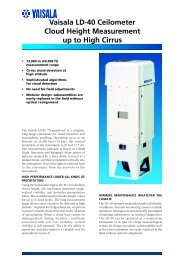
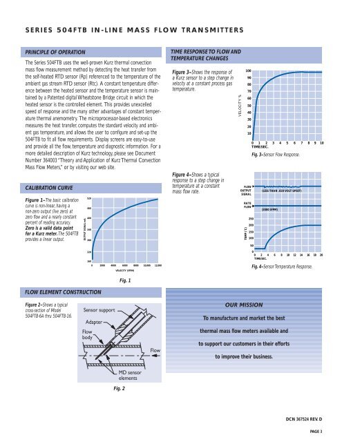
CALIBRATION CURVE<br />
Figure 1–The basic calibration<br />
curve is non-linear, having a<br />
non-zero output (live zero) at<br />
zero flow and a nearly constant<br />
percent of reading accuracy.<br />
Zero is a valid data point<br />
for a Kurz meter. The 504FTB<br />
provides a linear output.<br />
OUTPUT SIGNAL-mA<br />
520<br />
460<br />
400<br />
340<br />
280<br />
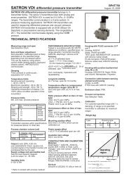
TIME RESPONSE TO <strong>FLOW</strong> AND<br />
TEMPERATURE CHANGES<br />
Figure 3–Shows the response of<br />
a Kurz sensor to a step change in<br />
velocity at a constant process gas<br />
temperature.<br />
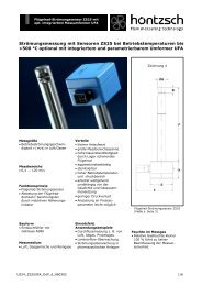
Figure 4–Shows a typical<br />
response to a step change in<br />
temperature at a constant<br />
mass flow rate.<br />
VELOCITY %<br />
<strong>FLOW</strong><br />
OUTPUT<br />
SIGNAL<br />
RATE<br />
<strong>FLOW</strong><br />
TEMP (˚C)<br />
100<br />
90<br />
80<br />
70<br />
60<br />
50<br />
40<br />
30<br />
20<br />
10<br />
0 1 2 3 4 5 6 7 8 9 10<br />
TIME/SEC.<br />
250<br />
200<br />
150<br />
100<br />
Fig. 3–Sensor Flow Response.<br />
50<br />
(LESS THAN .020 VOLT UPSET)<br />
(3000 SFPM)<br />
220<br />
160<br />
0<br />
2000 4000 6000 8000 10,000 12,000<br />
VELOCITY (SFPM)<br />
Fig. 1<br />
0<br />
0 2 4 6 8 10 12 14 16 18 20<br />
TIME/SEC.<br />
Fig. 4–Sensor Temperature Response.<br />
<strong>FLOW</strong> ELEMENT CONSTRUCTION<br />
Figure 2–Shows a typical<br />
cross-section of Model<br />
504FTB-6A thru 504FTB-16.<br />
OUR MISSION<br />
To manufacture and market the best<br />
thermal mass flow meters available and<br />
to support our customers in their efforts<br />
to improve their business.<br />
Fig. 2<br />
DCN 367524 REV. D<br />
PAGE 3