IN-LINE MASS FLOW TRANSMITTERS
IN-LINE MASS FLOW TRANSMITTERS
IN-LINE MASS FLOW TRANSMITTERS

You also want an ePaper? Increase the reach of your titles
YUMPU automatically turns print PDFs into web optimized ePapers that Google loves.
SERIES 504FTB<br />
<strong>IN</strong>-L<strong>IN</strong>E <strong>MASS</strong> <strong>FLOW</strong> <strong>TRANSMITTERS</strong><br />
SPECIFICATIONS cont’d.<br />
Safety Approvals:<br />
CSA Non-Incendive Approval:<br />
IEC 79-15 and EN60079-0/15<br />
ATEX Non-Incendive Approval:<br />
EN60079-0/15 and EN61241-1<br />
CSA Explosion-Proof Approval:<br />
IEC 79-01 and EN60079-01<br />
ATEX Flame-Proof Safety Approval:<br />
EN 60079-0/1<br />
Note: See Kurz website for the complete<br />
Safety Approvals Specifications.<br />
CE Directives:<br />
EMC,ATEX, LVD,WEEE and<br />
ROHS Directives for all<br />
models. PED Directives only<br />
for Models 504FTB-06, -06A<br />
-08, -12, -16, -24, -32 Consult<br />
Kurz for details.<br />
Serial Port Baud Rate:<br />
User selectable: 9600, 14,400,<br />
19,200, 38,400, 57,600.<br />
Communication Ports:<br />
RS485 Modbus ASCII or RTU<br />
Mode, and USB.<br />
LCD: Back-lit two-line alphanumeric<br />
with 16 characters<br />
per line.<br />
LCD Update:<br />
Every two seconds.<br />
Keypad: 20-button membrane<br />
mounted inside enclosure.<br />
LCD/Keypad Orientation:<br />
Adjustable in 90˚ increments<br />
to accommodate user<br />
viewing angle.<br />
Memory: EEPROM for all importtant<br />
data, with automatic<br />
sensor identification; Flash<br />
EEPROM for Program Memory.<br />
Net Weight:<br />
See Outline Drawings<br />
TECHNICAL DESCRIPTION cont’d.<br />
GREENHOUSE GAS REPORT<strong>IN</strong>G<br />
Beginning in2010, the EPA requires certain facilities to<br />
report GHG emissions.This rule is contained in US<br />
Code of Federal Regulations Title 40, Part 98. Kurz<br />
thermal mass flow meters meet the certification<br />
requirement in 40 CFR 98.34(c)(1) required by the<br />
Mandatory GHG Reporting regulation and are<br />
approved for this application.<br />
NAMUR NE43 COMPLIANCE<br />
Kurz meets the NAMUR NE43 recommendation<br />
for the 4-20 mA outputs to indicate a sensor or<br />
system fault. An NE43 alarm may be selected as high<br />
or low (but not both).This feature frees up the<br />
alarm/relays so that the user can set-up the relays<br />
for other needs.<br />
4-20 mA OUTPUTS<br />
The 4-20mA outputs may be wired as optically<br />
isolated loop-powered outputs or non-isolated, self<br />
powered outputs.The user may easily re-calibrate<br />
the 4-20 mA outputs using the CALIBRATE ANA-<br />
LOG OUTPUT menu in the onboard menu system<br />
or through the HART interface.<br />
RELAYS – ALARMS/PULSED<br />
TOTALIZER OUTPUT/PURGE OUTPUT<br />
The 504FTB can be ordered with up to 2 solid-state<br />
optically isolated relays.The relay outputs can be user<br />
configured to the following functions: alarm outputs<br />
or pulsed totalizer output. If no relays are ordered,<br />
the alarm functions are displayed on the LCD.<br />
Totalizers may be automatically reset at a specific<br />
total quantity (i.e., 10,000 SCF).<br />
ANALOG <strong>IN</strong>PUT<br />
One non-isolated 4-20mA input for use as a remote<br />
set-point for the built-in PID Flow Controller.<br />
PID <strong>FLOW</strong> CONTROLLER<br />
The 504FTB includes the capability of controlling the<br />
velocity or flow rate through the use of the user’s<br />
control valve, damper or position commanded 4-20<br />
mA interface device.The Set-Point may be internal<br />
or remote.<br />
USB PORT<br />
A USB port for terminal operations includes a COM<br />
emulator driver which can be accessed using a PC<br />
terminal emulator program to remotely “echo” the<br />
LCD and keypad functions and upload/download the<br />
system configuration and calibration data files using<br />
XMODEM protocol. Process data may be initiated<br />
manually through the Log Mode menu from the<br />
remote terminal/keyboard or the local LCD/keypad.<br />
The information may also be obtained automatically<br />
by configuring the Serial Data Logging through the<br />
onboard menu system.<br />
HART<br />
The Series 504FTB can be ordered with the HART<br />
communication interface.The HART protocol is a<br />
recognized and accepted standard in the process<br />
control industry.This interface provides the following<br />
benefits: remote configuration, remote diagnostic<br />
monitoring and on-line testing using available hand<br />
held configurators.<br />
MODBUS<br />
The Modbus local network protocol (ASCII or RTU)<br />
is included.The use of Modbus is extremely useful, as<br />
most features may be accessed, including configuration<br />
upload, download, etc.<br />
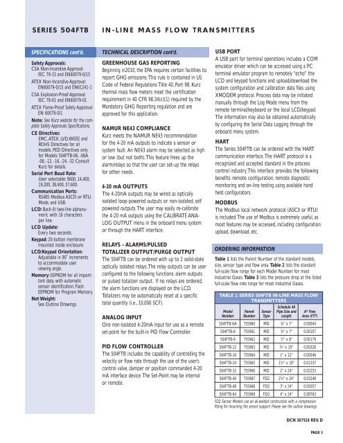
ORDER<strong>IN</strong>G <strong>IN</strong>FORMATION<br />
Table 1 lists the Parent Number of the standard models,<br />
size, sensor type and flow area. Table 2 lists the standard<br />
full-scale flow range for each Model Number for most<br />
Industrial Gases. Table 3 lists the pressure drop at the listed<br />
full-scale flow rate range for most Industrial Gases.<br />
TABLE 1: SERIES 504FTB <strong>IN</strong>-L<strong>IN</strong>E <strong>MASS</strong> <strong>FLOW</strong><br />
<strong>TRANSMITTERS</strong><br />
Schedule 40<br />
Model Parent Sensor Pipe Size and A* Flow<br />
Number Number Type Length Area (FT 2 )<br />
504FTB-6A 755960 MD 3<br />
⁄8" x 7" 0.00044<br />
504FTB-6 755961 MD 3<br />
⁄8" x 7" 0.00107<br />
504FTB-8 755962 MD 1<br />
⁄2" x 8" 0.00179<br />
504FTB-12 755963 MD 3<br />
⁄4" x 10" 0.00328<br />
504FTB-16 755964 MD 1" x 12" 0.00546<br />
504FTB-24 755965 MD 1 1 ⁄2" x 18" 0.01337<br />
504FTB-32 755966 MD 2" x 24" 0.02253<br />
504FTB-40 755967 FD2 2 1 ⁄2" x 24" 0.03248<br />
504FTB-48 755968 FD2 3" x 24" 0.05057<br />
504FTB-64 755969 FD2 4" x 24" 0.08763<br />
FD2 Sensor Models use an all-welded construction with a compression<br />
fitting for mounting the sensor support. Please see the outline drawings.<br />
DCN 367524 REV. D<br />
PAGE 5