SECTION 238219 - FAN COIL UNITS
SECTION 238219 - FAN COIL UNITS
SECTION 238219 - FAN COIL UNITS

You also want an ePaper? Increase the reach of your titles
YUMPU automatically turns print PDFs into web optimized ePapers that Google loves.
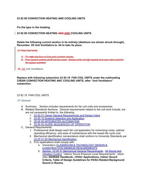
23 82 00 CONVECTION HEATING AND COOLING <strong>UNITS</strong><br />
Fix the typo in the heading.<br />
23 82 00 CONVECTION HEATING ANC AND COOLING <strong>UNITS</strong><br />
Delete the following current section in its entirety (deletions are shown struck through).<br />
Renumber .05 Unit Ventilators to .04 to take its place.<br />
.04 Fan Coil Units<br />
A. Do not use four or five port control valves.<br />
B. Fan speed control shall not be used. Select units at high speed and use valve control<br />
for space comfort.<br />
.05 .04 Unit Ventilators<br />
Replace with following subsection 23 82 19 <strong>FAN</strong> <strong>COIL</strong> <strong>UNITS</strong> under the subheading<br />
238200 CONVECTION HEATING ANC COOLING <strong>UNITS</strong>, after “Unit Ventilators”<br />
subsection.<br />
23 82 19 <strong>FAN</strong> <strong>COIL</strong> <strong>UNITS</strong><br />
.01 General<br />
A. Summary: Section includes requirements for fan coil units and accessories.<br />
B. Related Standards Sections: General requirements related to fan coil work include, but<br />
are not necessarily limited to, the following:<br />
1. 23 00 01 Owner General Requirements and Design Intent<br />
2. 23 00 10 Systems Selection and Application<br />
3. 25 00 00 INTEGRATED AUTOMATION<br />
4. 25 90 00 GUIDE SEQUENCES OF OPERATION<br />
C. General Requirements:<br />
1. Professional shall design each fan coil application for minimizing noise, optimal<br />
operating efficiency, and ease of maintenance with the lowest life cycle cost.<br />
2. Mechanical identification nomenclature shall conform to University Standards per<br />
23 05 01.05 Mechanical Identification.<br />
3. FCU applications shall comply with:<br />
a. University’s CLASSROOM & TECHNOLOGY DESIGN &<br />
CONSTRUCTION MINIMUM REQUIREMENTS.<br />
b. Section 23 05 01 Mechanical General Requirements, .04 Sound and<br />
Vibration Control, “Interior Sound Pressure Level Requirements”, which<br />
cites ASHRAE Handbook—HVAC Applications, Indoor Sound<br />
Criteria, Table of Design Guidelines for HVAC-Related Background<br />
Sound in Rooms.
c. ASHRAE 189.1: Water Use Efficiency; Energy Efficiency; Indoor<br />
Environmental Quality<br />
4. Designer shall provide an integrated mechanical system design and control<br />
sequence that will optimize dehumidification and avoid re-evaporation on cooling<br />
coil for each application.<br />
a. Common fan coil unit applications typically are poor at maintaining<br />
acceptable indoor humidity levels in spaces with latent loads, especially<br />
from unconditioned minimum ventilation air.<br />
i. At part load conditions (most of the time), constant speed fan<br />
operation has nearly zero net dehumidification efficiency and shall<br />
be strictly avoided where latent loads are present with partial<br />
sensible load.<br />
ii.<br />
Modulating cooling coil control valve to maintain space<br />
temperature directly can allow DAT under low load conditions to<br />
rise above dew point and thus no dehumidification can occur.<br />
b. Therefore FCU’s should generally only be applied as sensible<br />
cooling/heating applications. Options include:<br />
i. Dedicated Outdoor Air System (DOAS) to mechanically<br />
dehumidify the ventilation air; and<br />
ii.<br />
FCU’s with DAT limit control and high efficiency, variable-speed<br />
fans to maintain room temperature.<br />
5. Select high efficiency fan motors (ECM type) with variable speeds that can be<br />
automatically controlled to match load requirements in order to minimize fan<br />
noise, maximize fan energy and maximize potential for dehumidification during<br />
part load cooling operation. Refer to 25 90 00 GUIDE SEQUENCES OF<br />
OPERATION.<br />
6. Use demand based ventilation strategies such as CO2 sensors and/or zone<br />
occupancy sensors for “standby” mode for high variation of occupant density<br />
applications such as classrooms, assembly or large conference rooms.<br />
Coordinate with Electrical/Lighting design for dual use of occupancy sensors.<br />
7. Design for low flow, high temperature differences and variable flow distribution<br />
systems to minimize pump energy and optimize operation of central plant<br />
equipment.<br />
a. Selection of individual chilled water cooling coils in typical HVAC<br />
applications is recommended with a 14-16°F rise at peak conditions.<br />
b. Maintain average overall system chilled water temperature rise of at least<br />
12°F.<br />
c. For systems connected to University Park campus chilled water,<br />
i. Coordinate with 33 62 00 CAMPUS CHILLED WATER<br />
DISTRIBUTION<br />
ii.<br />
iii.<br />
iv.<br />
Cooling season: Design for campus chilled water at a supply<br />
temperature of 44°F.<br />
Winter Water Side Economizer: Chilled water coils that are<br />
expected to provide cooling year-round to isolated zones that are<br />
not practical to serve via airside economizer (examples:<br />
telecom/data closets, elevator equipment rooms) must be selected<br />
to function at a supply chilled water temperature maximum of<br />
48°F.<br />
Design to achieve a chilled water system return temperature to<br />
campus that is as warm as possible. Refer to choke valve control
sequence, which typically will not allow lower than 54°F return to<br />
campus.<br />
D. Quality Assurance and Uniformity:<br />
1. ARI Compliance: Test and rate fan-coil units in accordance with ARI Standard<br />
440 "Room Fan-Coil Air Conditioners".<br />
2. ASHRAE Compliance:<br />
a. DX Units: ASHRAE 15 for safety code for mechanical refrigeration.<br />
b. Applicable requirements in ASHRAE 62.1, Section 5 - "Systems and<br />
Equipment" and Section 7 - "Construction and Startup."<br />
i. LEED Prerequisite IEQ 1 requires compliance with requirements<br />
in ASHRAE 62.1, including requirements for controls, surfaces in<br />
contact with the airstream, particulate and gaseous filtration,<br />
humidification and dehumidification, drain pan construction and<br />
connection, finned-tube coil selection and cleaning, and<br />
equipment access. Verify, with manufacturers, availability of units<br />
with components and features that comply with these<br />
requirements.<br />
c. Applicable requirements in ASHRAE/IESNA 90.1 or ASHRAE 189.1 as<br />
required in 01 80 00 PERFORMANCE REQUIREMENTS<br />
3. Electrical Components, Devices, and Accessories: Listed and labeled as defined<br />
in NFPA 70, by a testing agency acceptable to authorities having jurisdiction, and<br />
marked for intended use.<br />
4. Equipment manufacturer shall be ISO-9001 certified.<br />
5. Provide equipment of same type by same manufacturer.<br />
E. Submittals: Documents shall require the following:<br />
1. Product Data: Include manufacturer’s specifications, rated capacities, operating<br />
characteristics, gages and finishes of materials, accessories, and furnished<br />
specialties.<br />
a. Submit color samples for selection by Architect with equipment to be<br />
installed in aesthetic areas.<br />
b. LEED Submittals (as applicable to project):<br />
i. Product Data for Credit EA 4: Documentation indicating that<br />
equipment and refrigerants comply.<br />
ii.<br />
Product Data for Prerequisite IEQ 1: Documentation indicating<br />
that units comply with ASHRAE 62.1, Section 5 - "Systems and<br />
Equipment."<br />
2. Shop Drawings: Detailed equipment assemblies including dimensions, weights,<br />
required clearances, components, and location and size of each field connection<br />
and installation instructions.<br />
a. Wiring Diagrams: Include requirements for power supply wiring and<br />
ladder-type wiring diagrams for interlock and control wiring. Clearly<br />
differentiate between portions of wiring that are factory-installed and<br />
portions to be field-installed.<br />
3. Maintenance Data: Include lubrication instructions, filter replacement, motor and<br />
drive replacement, and spare parts lists.<br />
4. Field quality-control test reports.<br />
5. Include all approved submittal data in maintenance manuals; in accordance with<br />
requirements of Section 23 01 00 OPERATION AND MAINTENANCE OF HVAC<br />
SYSTEMS.
.02 Product Requirements<br />
A. General: Provide fan-coil units having cabinet sizes, and in locations indicated, and of<br />
capacities, style, and having accessories as scheduled. Include in basic unit chassis,<br />
insulated cabinets, fans, motor, coils, drain pan, and filter.<br />
1. Provide factory-packaged and -tested units rated according to ARI 440,<br />
ASHRAE 33, and UL 1995.<br />
2. Include all features for fan-coil units that are required for Project, and identify<br />
additional features for specific units in the Fan-Coil-Unit Schedule on Drawings.<br />
B. Chassis: Galvanized steel where exposed to moisture, with baked-enamel finish and<br />
removable access panels.<br />
1. Floor-mounted units shall have leveling screws.<br />
C. Cabinets: Construct of minimum 18-ga steel removable panels.<br />
1. Exposed cabinet units:<br />
a. Units shall have published sound power level data tested in accordance<br />
with ARI Standard 350.<br />
b. Baked-enamel finish in manufacturer's [standard or custom] paint color<br />
as selected by Architect.<br />
c. Vertical Unit Front Panels: Removable, 16-ga front steel, with doubledeflection<br />
adjustable pattern discharge grille and channel-formed edges,<br />
cam fasteners, and insulation on back of panel. Provide optional minimum<br />
8” valve compartment extensions with opposite end coil connections on<br />
units with dual coils.<br />
d. Horizontal Unit Bottom Panels: Fastened to unit with cam fasteners and<br />
hinge and attached with safety chain; with discharge grille appropriately<br />
selected for the application.<br />
e. Steel recessing flanges for recessing fan-coil units into ceiling or wall.<br />
2. Concealed ducted units:<br />
a. Units shall have published sound power level data tested in accordance<br />
with ARI Standard 260-01.<br />
b. Steel with baked-enamel finish in manufacturer's standard paint color.<br />
c. Supply-Air Plenum: Sheet metal plenum finished and insulated to match<br />
the chassis with minimum 1” duct collar.<br />
d. Return-Air Plenum: Sheet metal plenum finished to match the chassis.<br />
e. Damper Plenum: Sheet metal plenum finished and insulated to match the<br />
chassis with outdoor- and return-air, formed-steel dampers.<br />
f. Dampers: Galvanized steel with extruded-vinyl blade seals, flexible-metal<br />
jamb seals, and interlocking linkage.<br />
D. Coil Section Insulation:<br />
1. Surfaces in contact with the airstream shall comply with requirements in<br />
ASHRAE 62.1, Airstream Surfaces for resistance to microbial growth and<br />
erosion.<br />
2. Provide Elastomeric Closed Cell Foam Insulation, conforming to:<br />
a. Antimicrobial Performance Rating of 0, no observed growth, per ASTM G-<br />
21.<br />
b. UL 181 for erosion<br />
c. NFPA 90A for fire, smoke and melting, and comply with a 25/50 Flame<br />
Spread and Smoke Developed Index per ASTM E-84 or UL 723.<br />
d. Polyethylene insulation is not acceptable.<br />
e. ASTM C 1071 and attached with adhesive complying with ASTM C 916.<br />
f. Thickness:
i. Minimum: 1/2” for surface condensation control.<br />
ii. Supplemental for energy efficiency as required per application:<br />
Provide Minimum Duct Insulation R-Value, Combined Heating and<br />
Cooling Supply Ducts and Return Ducts per ASHRAE 189.1 High<br />
Performance Building Standard.<br />
E. Fan Section:<br />
1. Direct-Driven Fans: Double width, forward curved, centrifugal; with permanently<br />
lubricated, multispeed motor resiliently mounted in the fan inlet. Aluminum or<br />
painted-steel wheels, and painted-steel or galvanized-steel fan scrolls. Plastic<br />
fans are prohibited.<br />
a. Fan and Motor Board: Removable<br />
b. Wiring Termination: Connect motor to chassis wiring with plug<br />
connection.<br />
c. Motors shall be ECM, variable-speed, DC, brushless motors specifically<br />
designed for use with single phase, 277 volt (or 120 volt), 60 hertz<br />
electrical input.<br />
i. Motor shall be complete with and operated by a single phase<br />
integrated controller/inverter that operates the wound stator and<br />
senses rotor position to electronically commutate the stator. All<br />
motors shall be designed for synchronous rotation. Motor rotor<br />
shall be permanent magnet type with near zero rotor losses. Motor<br />
shall be able to be mounted with shaft in horizontal or vertical<br />
orientation. Motor shall be permanently lubricated with ball<br />
bearings. Motor shall be direct coupled to the blower. Motor shall<br />
include integral thermal overload protection.<br />
ii. Motor shall maintain a minimum of 70% efficiency over its entire<br />
operating range.<br />
iii. Provide isolation between fan motor assembly and unit casing to<br />
eliminate any vibration from the fan to the terminal unit casing.<br />
Provide anti-back rotation system or provide a motor that is<br />
designed to overcome reverse rotation and not affect life<br />
expectancy.<br />
iv. Inductors shall be provided to minimize harmonic distortion and<br />
line noise. http://www.kruegerhvac.com/lit/pdf/white_powerquality.pdf<br />
v. Motor control module shall have built-in soft start and soft speed<br />
change ramps. Provide robust electronics and built-in surge<br />
protectors to protect the solid state controls from line transients.<br />
The motor control module shall include a variable speed mode to<br />
receive a variable control voltage signal to control the unit airflow<br />
directly from the DDC system in response to zone heating and<br />
cooling PID outputs.<br />
vi. Additional information:<br />
1. http://www.krueger-hvac.com/lit/pdf/whiteecm.pdf<br />
2. http://www.columbiaheating.com/page_images/file/GET-<br />
8068.pdf<br />
3. http://www.gotoevo.com/GEMotors.htm<br />
2. Belt-Driven Fans: Double width, forward curved, centrifugal; with permanently<br />
lubricated, single-speed motor installed on an adjustable fan base resiliently
mounted in the cabinet. Aluminum or painted-steel wheels, and painted-steel or<br />
galvanized-steel fan scrolls.<br />
a. Provide premium efficiency motor.<br />
b. Include inverter duty rated motor and VFD when required by High<br />
Performance Building Standard ASHRAE 189.1.<br />
F. Hydronic Coils: All cooling and heating coils shall optimize rows to meet the specified<br />
capacity and minimize air pressure drop.<br />
1. Seamless Copper tube, minimum 0.025” thick, with mechanically bonded<br />
aluminum fins, rated for a minimum working pressure of 250 psig at a maximum<br />
entering-water temperature of 200 deg F.<br />
2. Coil Casings shall be fabricated from galvanized steel.<br />
3. All water coils shall include manual air vent at high point and drain valve at low<br />
point in piping on coil side of isolation valve.<br />
G. Electric-Resistance Heating Coils: Avoid using to fullest extent possible. Where project<br />
conditions allow no better option, comply with the following.<br />
1. All heating elements on floor mounted units shall be finned tubular type.<br />
2. Nickel-chromium heating wire, free of expansion noise and hum, mounted in<br />
ceramic inserts in a galvanized-steel housing; with fuses in terminal box for<br />
overcurrent protection and limit controls for high-temperature protection.<br />
Terminate elements in stainless-steel machine-staked terminals secured with<br />
stainless-steel hardware.<br />
3. Silent solid state relays shall be supplied in exposed cabinet applications.<br />
4. Door interlocking disconnect switch.<br />
H. Main and Auxiliary Drain Pans: Fabricate pans and drain connections to comply with<br />
ASHRAE 62.1.<br />
1. Provide a primary drain pan extended under the entire coil section, constructed<br />
entirely of heavy gauge stainless steel for superior corrosion resistance. Drain<br />
pans shall be of one piece construction and be positively sloped for condensate<br />
removal. Drain pans shall be accessible and removable without requiring<br />
removal of coils.<br />
2. The primary drain pan shall be externally insulated with a fire retardant,<br />
elastomeric closed cell foam insulation. The insulation shall carry no more than a<br />
25/50 Flame Spread and Smoke Developed Rating per ASTM E-84 and UL 723<br />
and an Antimicrobial Performance Rating of 0, no observed growth, per ASTM G-<br />
21.<br />
3. Non-corrosive, insulated auxiliary drain pan shall be used for condensate from<br />
primary drain pan and piping accessories.<br />
4. Condensate Overflow Switch: A water level detection device conforming to UL<br />
508 shall be provided that will send an alarm and disable all mechanical cooling<br />
in the event that the condensate drain is blocked.<br />
a. The device shall typically be installed in the equipment-supplied drain<br />
pan, located at a point higher than the primary drain line connection and<br />
below the overflow rim of such pan.<br />
b. Refer to International Mechanical Code, Condensate Disposal, “Auxiliary<br />
and secondary drain systems” for optional methods.<br />
I. Filters: Synthetic, Multi-density, Depth Loading Media, minimum arrestance according to<br />
ASHRAE 52.1, and a minimum efficiency reporting value (MERV) below according to<br />
ASHRAE 52.2.<br />
1. ASHRAE 189.1 requires a minimum MERV rating of 8. Use in ducted units with<br />
higher fan static pressure capability.
2. LEED Prerequisite IEQ 1 requires compliance with ASHRAE 62.1, which requires<br />
a MERV rating of 6 or higher. Acceptable alternative to MERV 8 in units with<br />
minimal fan static pressure capability to ensure adequate airflow.<br />
3. Manufacturer: Tri-Dim, “Tri_Dek” Panel<br />
http://www.tridim.com/DesktopDefault.aspx?Product=Panel%20Filters&tabindex=<br />
1<br />
J. Piping Accessories:<br />
1. Runout piping to coils: Copper tube with wrought copper fittings and sweat<br />
joints. Piping system longevity is important so flexible hose kits are not<br />
recommended due to concerns with rubber deteriorating over time.<br />
2. Isolation valves: Two-Piece Ball Valves: Bronze body with full-port, chromeplated<br />
bronze ball; PTFE or TFE seats; and 600-psig minimum CWP rating and<br />
blowout-proof stem.<br />
3. P/T Ports on inlet and outlet of each coil per 23 05 19 Measuring Instruments for<br />
HVAC.<br />
4. Balancing device: typically not required for small units on variable flow systems.<br />
Refer to further details in 23 05 01 Mechanical General Requirements, .02<br />
Valves, “Balancing Valves”.<br />
5. Bronze/Copper Unions: ASME B16.22. Include to provide a mechanical<br />
connection between the coil and valve package that can be connected,<br />
disconnected, and re-connected without the need to cut tubing or unsolder a<br />
joint. Dielectric unions are prohibited.<br />
6. Y-Pattern Hydronic Strainers: Cast Bronze; minimum 400-psig working<br />
pressure, 250 F working temperature; with threaded connections, bolted cover,<br />
stainless-steel screen, and bottom drain connection. Include nominal ¼” balltype<br />
blowdown valve with minimum ½” hose-end connection on blowdown leg to<br />
allow backflushing the strainer screen without removing the plug.<br />
K. Miscellaneous Accessories:<br />
1. Locks: Provide tamperproof fasteners on access doors and front panel for<br />
exposed cabinet units.<br />
L. Electrical: Units shall operate on electrical power as specified on the equipment<br />
schedule. All wiring shall be in flexible metal conduit.<br />
M. Controls:<br />
1. Coordinate control devices and operational sequences with Section 25 00 00<br />
INTEGRATED AUTOMATION and 25 90 00 GUIDE SEQUENCES OF<br />
OPERATION<br />
2. Coordinate and complete wiring from unit mounted control devices to BAS<br />
equipment controller.<br />
3. Typically provide two-way, modulating, characterized control valves for hydronic<br />
coils. Refer to BAS Guidespec, “Control Valves”.<br />
4. DAT sensors shall be quality averaging type and/or located sufficiently<br />
downstream of coils to achieve accurate reading and DAT limit control.<br />
.03 Execution<br />
A. Installation
1. General: Install fan coil units and accessories in strict accordance with the<br />
manufacturer's installation instructions for maintaining optimum performance and<br />
serviceability.<br />
a. Maintain manufacturer's and University recommended clearances for<br />
service.<br />
b. Coordinate with other trades to assure correct recess size for recessed<br />
units.<br />
2. Suspend horizontal concealed fan-coil units from structure with properly selected<br />
vibration isolation hangers.<br />
3. Verify locations of thermostats and other exposed control sensors with Drawings<br />
and room details before installation.<br />
4. Install new filters in each fan-coil unit within two weeks after Substantial<br />
Completion.<br />
5. Piping installation requirements are specified in other Sections. Drawings<br />
indicate general arrangement of piping, fittings, and specialties. Specific<br />
connection requirements are as follows:<br />
a. Install piping adjacent to equipment to allow service and maintenance.<br />
b. Connect piping to fan-coil-unit factory hydronic piping package. Install<br />
piping package if shipped loose.<br />
c. Connect condensate drain to indirect waste.<br />
d. For concealed and ducted fan-coil units, install condensate trap of<br />
adequate depth to seal against the pressure of fan. Install cleanouts in<br />
piping at changes of direction.<br />
6. Connect supply and return ducts to fan-coil units with flexible duct connectors.<br />
7. Protect exposed cabinet units with protective covers during balance of<br />
construction.<br />
B. FIELD QUALITY CONTROL<br />
1. Perform the following field tests and inspections and prepare test reports:<br />
a. Operational Test: After electrical circuitry has been energized, start units<br />
to confirm proper motor rotation and unit operation.<br />
b. Operate electric heating elements through each stage to verify proper<br />
operation and electrical connections.<br />
c. Test and adjust controls and safety devices. Replace damaged and<br />
malfunctioning controls and equipment.<br />
2. Remove and replace malfunctioning units and retest as specified above.<br />
END of revision<br />
Update Commentary:<br />
Section was updated primarily for the following reasons:<br />
1) To expand this section into a 3 part format to more fully define requirements.<br />
a. Part 01: To list General Owner Requirements of design intent, selection criteria,<br />
quality assurance, submittals. Crucial issues include:<br />
i. Integrated system design must account for adequate dehumidification.<br />
ii. Ensuring acceptable Sound and Vibration levels<br />
b. Part 02: To list the Product Requirements for manufactured equipment.<br />
i. Energy Efficient ECM fan motors with auto variable speed controls
ii. Thermal Insulation performance meeting High Performance Building<br />
Standard for IAQ and energy efficiency.<br />
iii. Filters (MERV 6-8)<br />
iv. Accessories<br />
v. BAS Controls coordination<br />
c. Part 03: To list the Execution (Installation, Connections, and Start-up/functional<br />
performance testing) requirements.