Instruction Manual - AerodromeRC
Instruction Manual - AerodromeRC
Instruction Manual - AerodromeRC

You also want an ePaper? Increase the reach of your titles
YUMPU automatically turns print PDFs into web optimized ePapers that Google loves.
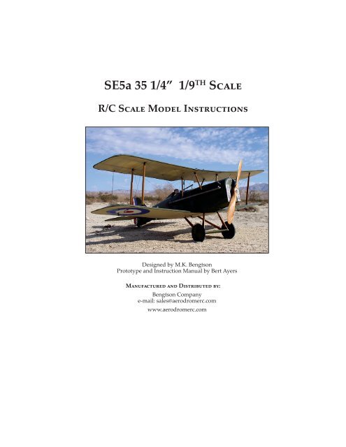
SE5a 35 1/4” 1/9 TH S<br />
R/C S M I<br />
Designed by M.K. Bengtson<br />
Prototype and <strong>Instruction</strong> <strong>Manual</strong> by Bert Ayers<br />
M D :<br />
Bengtson Company<br />
e-mail: sales@aerodromerc.com<br />
www.aerodromerc.com
www.<strong>AerodromeRC</strong>.com<br />
SE5a 35 1/4” 1/9 <br />
Thank you for buying the <strong>AerodromeRC</strong> SE5a 1/9th<br />
scale laser cut short kit for electric flight.<br />
MODEL SPECIFICATIONS<br />
More than 365 Laser Cut parts<br />
Scale: 1/9th<br />
Prop: 10x6<br />
Channels: R/E/A/T or R/E/T<br />
Wheels: Balsa and plywood with Neoprene foam tires<br />
Wingspan: 35 1/4”<br />
Airfoil Type: Blat boomed with mini rib included<br />
Wing Area: 439 sq in<br />
Cowl: N/A<br />
Weight: ~29 oz ready to fly<br />
Power System: MP Jet geared 4:1 S400/480 or most likely<br />
MP Jet BL<br />
Designer: M.K. Bengtson<br />
Prototype Builder: Bert Ayers<br />
THE MODEL<br />
SE5a 35 1/4” 1/9th Scale Page 2<br />
Pushing them out without cuing the bridges may<br />
break the part. Pick the part out with the point of the blade.<br />
If it doesn’t come out easily, turn the sheet over and find<br />
the area where the laser didn’t cut thru – re-cut that area,<br />
then take the part out.<br />
A semi scale adaptation for the Royal Aircra Factory’s<br />
SE5a, this model is designed to be easy to build and exciting<br />
to fly. Self aligning wings for fast, accurate assembly.<br />
POWER SET UP<br />
The model is designed to be powered by the MP Jet 4:1<br />
BB Gearbox with 6v Speed 400 or MP Jet Brushless motor.<br />
Equivalent rated motors can be used, but must be adapted<br />
to the mounting plate furnished.<br />
R/C GEAR<br />
A four function mini receiver and four micro servos are<br />
all that are required. Aileron servos can be no thicker than<br />
11 mm to fit into the aileron servo bay.<br />
BEFORE STARTING THE BUILD<br />
Use the plastic bag that the kit comes in to cover the<br />
plans in each of the building steps. Slit the bag down the<br />
side and sealed end to open it up into one large sheet.<br />
Laser cut parts can best be taken out of the balsa sheets<br />
by using a #11 X-acto blade to cut the minute bridges in the<br />
laser cuts<br />
All strip wood, spars and leading edge pieces are provided<br />
in this kit. Aer cuing the mini bridges on the strip<br />
wood, sand lightly the lile bump that is le from the mini<br />
bridge.<br />
On this model, CA glue was used for all balsa joints.<br />
Elmer’s Carpenters Glue was used for all laminating and<br />
Epoxy for joints in the motor mount area.<br />
TAIL SURFACES<br />
The tail surfaces are a good place to start – to get acquainted<br />
with building with laser cut parts. Find all “S”<br />
parts in the 1/8” balsa laser sheet, cut the small bridges<br />
and pick the parts out of the sheet. Cover the plans with<br />
the shipping bag and pin down the “S” parts. Some 1/8”<br />
square pieces will be needed for the ribs. CA glue all joints<br />
and allow to set for 5 minutes then remove from the plans.<br />
You have just built the Vertical Stabilizer and the Rudder.<br />
You can sand the parts now (round all the leading and<br />
trailing edges – do not round S1 boom) or leave to later to<br />
sand.<br />
Find all the “H” parts and pin down to the Horizontal<br />
plan, and add the ribs. Find all the “E” parts and pin down<br />
Copyright© 2007-11 M.K. Bengtson All Rights Reserved Rev 07/11
www.<strong>AerodromeRC</strong>.com<br />
SE5a 35 1/4” 1/9th Scale Page 3<br />
glued to the rear of the spar, the first three ribs must have<br />
this space le open. Find 1/8” balsa ribs “L2 and L4”, pin<br />
L4 in position. Note that rib L2 has two notches on the top<br />
surface. This is where the wing struts will be glued in on<br />
final assembly. You need to glue 1/8” square balsa – 1/2”<br />
long on either side of both notches, then sand to the rib<br />
shape. These give side support to the struts and also an<br />
area to glue the covering. Pin L2 in position. Pin 1/8” rib<br />
R13 (aileron) in position – avoid gluing to R4 and rear spar.<br />
CA glue all other joints.<br />
Find the 1/16” balsa sheet and take out ribs – L1, R3, R4.<br />
next to the Horizontal Stabilizer, add the ribs. CA glue all<br />
joints. If you plan to use a push rod for the elevator, you<br />
will need to bend 1/16” music wire to match the plans and<br />
solder on a control horn. If you plan to use the “pull-pull”<br />
cable system, you can glue in a 1/8” birch dowel or aluminum<br />
tube to join the elevators (as this builder did) or<br />
leave them separate. It is recommended that you join the<br />
elevators as it will be much easier to rig the elevator cables.<br />
The 1/16” plywood control horns are usually le until aer<br />
covering to be glue in. Sand now or leave till later.<br />
Now that you are an expert at building with laser cut<br />
parts, we can proceed with more complicated structure.<br />
WINGS<br />
The wing parts require a lile prep work before assembly<br />
can begin. Study the plans to see that although all<br />
four wing panels look the same, there are differences in<br />
the upper and lower wing panels. All the balsa necessary<br />
to build the wings is furnished in the kit (except the 1/32”<br />
balsa sheeting). The photos will show the le wing panel<br />
being built. This builder likes to build both panels at the<br />
same time, doing each step on both wings. Cover the plans<br />
with the shipping bag.<br />
Starting with the boom wing – find the 1/8” x 1/4”<br />
balsa spar material and cut to length on the plans. Find the<br />
“WTE” and “ALE” parts in the 1/8” balsa sheet. The WTE<br />
needs to be glued to the REAR spar wing tip end. Pin the<br />
spars down to the plan. Pin ALE in position – avoid gluing<br />
ALE to the rear spar. Find 1/16” plywood “R-8, R-9” and<br />
pin down to the plans. Do the same with 1/32” plywood<br />
trailing edge. Find 1/8” balsa Rib “L1” and pin in position.<br />
Use the fixture “RAG” to lean the rib toward the wing tip.<br />
Be aware that a 1/16” plywood dihedral brace will later be<br />
R5, R10 R11 and R12. From the 1/8” sheet, find parts “m”<br />
and “p” - also the triangular pieces that reinforce the joint<br />
rear spar and R8, R9 and ALE ( found in center cut out of<br />
F3). Put all these parts in position and CA glue. Note that<br />
“m” goes on the boom of the ribs and “p” is flush with<br />
the top of the ribs, leaving space for the 1/32” plywood<br />
top trailing edge. The 1/32” plywood trailing edge piece<br />
can now be put in place. This builder ran a small bead of<br />
carpenters glue along the outside edge, as well as on each<br />
rib. The 3/16” square leading edge (provided in the kit) can<br />
now be glue on. Gather together 18 - “R4m” leading edge<br />
ribs, put two in between each full rib starting at R3, at an<br />
angle, then straighten out to fit in correct position. Add R4n<br />
and R4p at the tip. Sheet between ribs L1 with 1/32” balsa<br />
sheet.<br />
AILERON BAY<br />
Find the 1/32” plywood sheet aileron servo cover (with<br />
the wheel rims). Find 4 pieces of 1/8” x 1/4” bass wood that<br />
will fit between Ribs R5 in the aileron bay. Recess them<br />
1/32” so that the servo cover will be even with the boom<br />
of the rib. This builder choose to secure the covers with #40<br />
x 1/4” screws. This builder used HS-55 servos which are<br />
about 1 mm to wide. When installed, there is a slight bump<br />
in the top of the wing covering. Hardly visible. Masking<br />
tape was put on the side of the servo, to be secured to the<br />
Copyright© 2007-11 M.K. Bengtson All Rights Reserved Rev 07/11
www.<strong>AerodromeRC</strong>.com<br />
servo cover. Thick CA glue was put on the masking tape<br />
then positioned on the servo cover. Very easy and secure<br />
way of mounting the servo. Servo can be removed by putting<br />
#11 blade under the masking tape and pealing it away.<br />
SE5a 35 1/4” 1/9th Scale Page 4<br />
To connect the servo to the aileron control horn, bend<br />
a piece of .039” music wire to the correct length with “z”<br />
bends on each end. A “V” bend included in the length<br />
allows for adjustment of length by opening or closing the<br />
“V”. The servo arm can be put on the “z” bend by unscrewing<br />
the cover plate.<br />
Other methods are available. This builder used this approach<br />
because it seems to be easy and unobtrusive.<br />
Complete the upper wing in the same manner as the lower<br />
wing. The 1/32” plywood Aileron Link Horn will be glued<br />
in “m” on top of the boom wing and on the boom of the<br />
top wing aer the wings are covered. This builder suggests<br />
that you sand the wings now while they in smaller panels,<br />
rather than when assembled with the center sections, and<br />
harder to handle.<br />
WING CENTER SECTIONS<br />
Build both sections at the same time. Find the 1/16”<br />
plywood dihedral braces. This is a good time to check the<br />
wing panels to see that the braces fit in their slots easily.<br />
Cut 1/8” x 1/4” spar material to lengths. Pin the spars into<br />
position. For the top section, find R1a ribs and glue the 1/8”<br />
square x 1/2” long pieces on the boom of the ribs covering<br />
the strut notches. Make a le and right pair. Pin them in<br />
place (they must be square to the building board). For the<br />
boom section, ribs R2 (square also). Find ribs R0 and L0,<br />
pin or glue. Pin down CS1 and CS3 on the top section – LS1<br />
on the lower section.CA glue the joints.<br />
Add the CS2 and LS2 wedges. Cut lengths of 3/16” leading<br />
edge balsa and glue in position.<br />
Sand lightly the rear part of each section so that the<br />
sheeting will fit smoothly. Still pinned down, Sheet both<br />
sections with 1/32” balsa (noted by the cross hatch lines<br />
on the plans). Remove from the plans. Glue in the 1/16”<br />
plywood dihedral braces – outboard side of brace should<br />
go UP.<br />
Building the top wing is prey much the same as the<br />
boom wing, with these few exceptions.<br />
Ribs R1 and R6 have the strut notches on the boom.<br />
Glue the 1/8” square x 1/2” long pieces on both sides of R5<br />
and only on the outboard side of R1 (make a le and a right<br />
R1). Rib R1 is 1/16” balsa. It will be joined with 1/16” balsa<br />
rib R1a of the center section to provide the 1/8” Cabane<br />
Strut mounting notch. There is no 1/32” balsa sheeting on<br />
the first rib bay. And 1/8” balsa piece “p” is on the boom<br />
of the rib.<br />
ASSEMBLING THE WINGS<br />
Start with the boom wing. Pin the center section down<br />
to the wing plan. Cut two pieces of scrap balsa to 1” x 8”<br />
and pin down to the plans (vertically) on the outboard<br />
aileron bay rib R5. There is a dashed line on the plans noting<br />
1” dihedral. Trial fit each wing panel to see that it fits<br />
on to the dihedral brace easily and flush against R2 – sand<br />
where necessary for a perfect fit. This builder used a piece<br />
of wood as a strait edge to get the leading edges straight.<br />
When satisfied all is perfect – glue it!<br />
Copyright© 2007-11 M.K. Bengtson All Rights Reserved Rev 07/11
www.<strong>AerodromeRC</strong>.com<br />
SE5a 35 1/4” 1/9th Scale Page 5<br />
Repeat the same procedure with the top wing. Wow!<br />
Two beautiful wings.<br />
Lay the right fuselage side on the plans and mark the<br />
location if the 5 1/8” balsa fuselage formers. There are<br />
notches for them to fit into, but a line square to the top<br />
helps to make them perfect. The motor mount plate will<br />
be glued in at this time also. This is the time to modify the<br />
mounting plate to suit your power set up. This builder<br />
uses epoxy to glue the plywood mounting plates (motor<br />
and landing gear) CA glue for other formers. Make sure all<br />
formers are square.<br />
BUILDING THE FUSELAGE<br />
Find the two 1/8” balsa fuselage sides and the 1/32”<br />
plywood doublers. Laminate the doublers to the sides. Be<br />
sure to make a LEFT and RIGHT side. Find 6 LGM1 1/16”<br />
plywood plates. Laminate 2 together to make 3 plates<br />
– holes lining up, of course.<br />
Add the le fuselage side. The LGM1 are epoxied in<br />
place, make sure the lacing holes line up with the boom<br />
of F3. Find the 1/8” balsa TK1 and former F6a and glue in<br />
place. This builder added the cockpit floor and the mounting<br />
rails for the elevator/rudder servos and checked that<br />
the motor/gearbox were in proper position while the fuselage<br />
is open.<br />
The top fuselage sheeting will have to be done in 3<br />
pieces. You will note that from F1 to F4 the sheeting is flat.<br />
From F4 to F5 it raises. Then from F5 to F6a it goes down.<br />
Copyright© 2007-11 M.K. Bengtson All Rights Reserved Rev 07/11
www.<strong>AerodromeRC</strong>.com<br />
Do not aempt to do the sheeting in one sheet – it will be<br />
ugly! This builder likes to prebend the sheeting before gluing<br />
it to the fuselage. This also makes the 3 pieces easier to<br />
fit. Soak the sheeting in hot water, then tape it to a cylinder<br />
similar in diameter to the formers. Let it dry overnight.<br />
A paper paern can be made to help cut the sheeting<br />
(aer it is pre bent).<br />
SE5a 35 1/4” 1/9th Scale Page 6<br />
glue the 1/8” square strips. Leave the section on the plans<br />
(cover) and build a second side right on top of the first section.<br />
When dry, remove from the plans.<br />
Find parts 1/8” balsa TS3 and TS4. On the top view<br />
plans – a section, pin down TS3. Cut 2 each 1/8” square<br />
cross members. Cut 1 piece 1/8” square to size just in front<br />
of TS4. (F10).<br />
The a of the side pieces need to be soaked in very hot<br />
water (just the section a of F9), this will facilitate bending<br />
them around the slight curve to TS3 and 4. Pin the side<br />
pieces down to the plans in the forward straight sections,<br />
then carefully pull the rear section around the curve.<br />
Glue in TS4 and the cross member just in front of it.<br />
Make sure the tail post is square to the building board.<br />
Starting a, glue in each cross member (top and boom),<br />
again square it.<br />
Building the a section – cut the rest of the 1/8” square<br />
balsa strips from the sheet and sand off the bumps le from<br />
the mini bridges. Cover the plans and pin down and<br />
Allow the a section to dry overnight then remove<br />
this section from the plans. 1/8” balsa parts TS5, 6 ,7 and 8<br />
can be added, note the order on the plans, as this sets the<br />
incidence if the Horizontal Stabilizer. Time to join the front<br />
and a sections together. Pin the front fuselage section on<br />
the top view of the plans. Cut a scrap piece of balsa 1 7/16”<br />
high and pin to the plans at the tail post. Slide the side<br />
longerons into the slots in the front fuselage and set the tail<br />
post on the scrap balsa piece. Align the tail post with the<br />
plans center line. Make sure all is square. When satisfied<br />
with the fit, glue it together. Add the formers F7, 8 and 9.<br />
Add the 1/8” balsa piece TK2, then the 2 F10 pieces.<br />
The 1/16” square balsa stringers are not furnished in<br />
the kit. This builder cut them from the excess on the laser<br />
sheets. The TS1 tail skid can be added aer covering. Add<br />
the stringers and the fuse is ready to sand. This builder<br />
Copyright© 2007-11 M.K. Bengtson All Rights Reserved Rev 07/11
www.<strong>AerodromeRC</strong>.com<br />
finished off the head rest and added slots for the control<br />
wire exits, as well as a piece of 1/8” balsa on each side of<br />
the slot for S1 of the vertical.<br />
SE5a 35 1/4” 1/9th Scale Page 7<br />
to some type of board and cut them out. Tape them to the<br />
fuselage. This is a fairly important step, so try to be as accurate<br />
as possible.<br />
FRONT RADIATOR<br />
Find 1/4” balsa pieces C1 and 2. Laminate together. Find<br />
2 -1/2” lengths of 1/8” dowels. Note that 2 dowel pin holes<br />
in C1 will match the holes in F1. Glue in the dowel pins.<br />
This builder used 2 mini magnets to hold the radiator to the<br />
fuselage. Sand to shape on the plans. The radiator louvers<br />
(C3) can be added now or later.<br />
Tape the wing to the fixture. Triangulate from the wing<br />
tip to the tail post to make sure wing is perpendicular<br />
to the center line. Put the fuselage on the building board<br />
and measure up to the wing tips to make sure the wing is<br />
square to the fuselage. Trial fit the struts until your are satisfied<br />
that they fit perfect. Epoxy the joints at the fuselage.<br />
CABANE STRUTS<br />
Find the 4 -1/8” lite plywood cabane struts CB1 and<br />
2. Pre finish them by sanding round edges, staining and<br />
soaking them with CA glue to add strength to them. The<br />
cabane struts can be mounted at this time or le until final<br />
assembly. This builder highly recommends that they be<br />
mounted now while the fuselage is open and the aach<br />
points can be finished off easily. Either way, a fixture will<br />
have to be made to set the wing incidence and position on<br />
the fuselage. This builder likes to use simple corrugated<br />
board fixtures. Draw on tissue paper on the plans where<br />
the fore and a position of the top wing (with incidence).<br />
Use the F1 and F5 as reference points. Be sure to mark<br />
where former F3 should aach, as you will see that the forward<br />
cabane strut aaches to the wing at that point. Make a<br />
tracing on F3 with a center line and angles up to where the<br />
wing center section mounting slots are. Glue the tracings<br />
Remove the wing and the fixture. Save the fixture as it will<br />
be used again at final assembly.<br />
Copyright© 2007-11 M.K. Bengtson All Rights Reserved Rev 07/11
www.<strong>AerodromeRC</strong>.com<br />
It is nice to do this step now while everything is open.<br />
Finish the joints around the fuselage.<br />
LANDING GEAR<br />
Get a length of 1/16” music wire and cut and bend to<br />
match the drawing on the plans.<br />
SE5a 35 1/4” 1/9th Scale Page 8<br />
The problem is to assemble and solder the wires to the<br />
measurements on the plans. This builder likes to make a<br />
soldering fixture. Use simple materials mounted on a base<br />
board that has the measurements from the plans. Some rebending<br />
of the wires may be necessary to make fit perfectly.<br />
When the fit is perfect, wrap with copper wire and solder.<br />
WHEELS<br />
Find the wheel parts. Use a brass tube to center the<br />
1/32” ply rim plates on the 1/4” balsa wheel cores. Add<br />
the 1/8” ply collars. Message the Neoprene foam rod into<br />
a circle, then CA glue the ends together. Take time to get a<br />
smooth joint. Roll the Neoprene tire onto the balsa core. CA<br />
glue the Neoprene to the 1/32” ply rims. Use the CA sparingly,<br />
as it really likes the Neoprene.<br />
Transfer the spoke cone paern on the plan to heavy<br />
card stock. Cut out the circle. Use a ball point pen to score<br />
each line to make an impression of “spokes”. Fold the<br />
paper along each line to exaggerate the raised lines. Cut<br />
one spoke line to the center and overlap to the next spoke<br />
line to make a cone, use white glue. The inside cone may be<br />
aached to the wheels. They will need a small hole in<br />
Next we need to add the landing gear struts and the<br />
landing gear underwing. Find the 1/16” balsa strut material.<br />
Note the location of the strut to the wire – each is<br />
different. Mount the front strut with the wire in the back.<br />
Mount the rear strut with the wire in the front. This builder<br />
uses epoxy for this step for added strength and flex. Find<br />
the 1/16” balsa parts U3 and 4 and pin them down on the<br />
plans. CA glue the !/8” balsa part U1 on each end. Glue<br />
the 1/16” balsa parts U2 in their positions. Remove from<br />
the plans and mount on the landing gear axle between the<br />
struts. The underwing should be parallel with the boom<br />
wing when mounted on the fuselage. Add the other U1<br />
and 2 parts to the unfinished side of the underwing. Sand<br />
the whole assembly.<br />
Copyright© 2007-11 M.K. Bengtson All Rights Reserved Rev 07/11
www.<strong>AerodromeRC</strong>.com<br />
the center of the cone. The outside cones may be attached<br />
at this point if wheel collars are used. Alternatively,<br />
aer installing the wheel on the axle, a washer may be<br />
soldered to hold the wheel in place and then the cone attached.<br />
This method makes a very scale appearance.<br />
TRIAL FIT<br />
Time to put everything together to see how everything<br />
fits and to see how it looks. Wow!<br />
SE5a 35 1/4” 1/9th Scale Page 9<br />
FINAL ASSEMBLY<br />
This model is designed to be easy to assemble. Assembly<br />
starts with the boom wings.<br />
Slide the boom wing center section onto the boom of<br />
the fuselage (should be a perfect fit).<br />
Put the wing and fuse on the worktable and square the<br />
fuse with the table. Measure the wing tips, they should be<br />
at the same height. Triangulate the wing tip with the fuse<br />
tail post, measure needs to be the same. Trim and sand<br />
where necessary on the fuselage to make these measurements<br />
perfect. When you are happy with the results, glue<br />
it!<br />
COVER THE MODEL<br />
If everything fits well and is nicely sanded, it is time<br />
to cover your model. This is also a good time to trial fit<br />
the radio system and push rods if used. Use your favorite<br />
method to cover the model and prime and sand the sheet<br />
balsa areas. This builder choose to cover with Polyspan<br />
adhered to the structure with Sig Stix-it. MinWax Polycrylic<br />
was use for the filler. This builder likes to paint the Roundels,<br />
Numbers and any other designs before the model is<br />
assembled.<br />
This includes Cockpit Combing, Windshields, Machine<br />
Guns, Exhaust Pipes, Engines, etc., anything that is difficult<br />
to put on aer the model is assembled.<br />
MAKING SCALE DETAILS<br />
You can add whatever scale details you are comfortable<br />
with making. Almost everything is furnished in the kit to<br />
detail this model. This builder used everything.<br />
Re tape the wing fixture (the one you made to position<br />
the cabane struts) or if you didn’t do that step, do it now.<br />
Lightly tape the wing to the fixture. Invert the model on<br />
the worktable, square the fuselage and triangulate the top<br />
wing to the tail post in the same manner as the boom<br />
wing. Interplane struts can be used to temporarily support<br />
the wings. Make sure the top wing is parallel to the bottom<br />
wing on both sides. When you are satisfied, apply the<br />
epoxy to the center section.<br />
Fit the interplane struts. This builder also made a cardboard<br />
fixture (from the plans) to glue the struts and wings<br />
at proper incidence. Glue when you are satisfied.<br />
Copyright© 2007-11 M.K. Bengtson All Rights Reserved Rev 07/11
www.<strong>AerodromeRC</strong>.com<br />
SE5a 35 1/4” 1/9th Scale Page 10<br />
The Horizontal Stabilizer/Elevator should slip easilyinto<br />
the slots at the rear. The stab needs to be parallel with the<br />
wings and it needs to be triangulated – stab tip to wing tip.<br />
You can eyeball the parallel with the wings and measure<br />
the triangulation. Glue when satisfied.<br />
CONNECTING THE AILERONS<br />
Aer covering the ailerons, find the 1/32” plywood<br />
aileron control horns. Cut out the slot in part “p” on the<br />
upper surface of the lower wing and on the underside of<br />
the top wing. Glue in the control horn (make sure the hole<br />
is open). Aer final assembly of the wings to the fuselage,<br />
the ailerons need to be connected. Tape the ailerons in the<br />
neutral position. Use<br />
1/16” music wire to connect them. If you have a favorite<br />
method to do this, use it. This builder choose to use “Z”<br />
bends at both ends. To do this, 2 lengths of wire are needed<br />
with a 1/2” brass tube coupler. With the ailerons at neutral<br />
with the rest of the wing, solder the 2 lengths with the coupler.<br />
This makes an unobtrusive installation.<br />
The Vertical Stabilizer/Rudder needs to be square to the<br />
Horizontal Stabilizer. Glue it.<br />
Copyright© 2007-11 M.K. Bengtson All Rights Reserved Rev 07/11
www.<strong>AerodromeRC</strong>.com<br />
LACING THE LANDING GEAR<br />
Aach the landing gear to the mounting plates in your<br />
favorite. This builder likes fishing line.<br />
SE5a 35 1/4” 1/9th Scale Page 11<br />
CONTACT INFORMATION<br />
Bengtson Company<br />
e-mail: sales@aerodromerc.com<br />
Web Site: www.aerodromerc.com<br />
Everything has been done except the radio and baery<br />
hatch in the boom of the fuselage. This builder will leave<br />
that challenge for you to solve – if you have goen this far<br />
– you are now an expert model builder! Congratulations,<br />
you have built a beautiful model. Send photos of your<br />
model to the <strong>AerodromeRC</strong> Gallery.<br />
If you choose to add flying wires, use strong thread,<br />
Kevlar fishing line or elastic beading cording to simulate<br />
the rigging. Use small screws, fishing hook eyes, straight<br />
pinheads or small eyelets for aach points. While not technically<br />
required, these wires can add a degree of strength<br />
to your model.<br />
This model is very easy to balance (use the CG mark on<br />
the plans). It has a long nose so that the baery can be easily<br />
moved between F1 and F3.<br />
BALANCING THE MODEL<br />
Balance the model at the point shown. Choosing a<br />
larger baery is preferred to adding lead.<br />
FLYING<br />
The model should ROG on grass, pavement or hard<br />
surfaces. The model may require coordinated turns using<br />
both ailerons and rudder control. This is due to adverse<br />
yaw. Halving the aileron down throw may reduce the yaw.<br />
This effect can be accomplished by rotating the control arm<br />
of the aileron servo forward about 20 degrees.<br />
Let the model gain altitude slowly off the runway. Applying<br />
too much up elevator at slow speeds risks a stall.<br />
Make your turns gently as tight turns risk tip stalling in<br />
any model. Don’t expect the elevator to make the model<br />
climb. Think of the elevator as a device to change the aitude<br />
of the model. The wing and airspeed ultimately make<br />
the model climb. Oen down elevator applied at stalling<br />
can avoid a major crash. The most important details for<br />
proper flight operations are:<br />
• CG location. Tail heavy models never fly well or at all.<br />
• Down and right thrust<br />
• Straight and non warped wings<br />
Copyright© 2007-11 M.K. Bengtson All Rights Reserved Rev 07/11